DESIGN AND TESTS OF A WEARABLE FUNCTIONAL
ELECTRICAL STIMULATION (FES) SYSTEM
FOR KNEE JOINT MOVEMENT USING CYCLE-TO-CYCLE
CONTROL METHOD
1
AIDATUNISADINA LINAZIZAH BASITH, 2STANLEY SETIAWAN, 3ACHMAD ARIFIN,
4FAUZAN ARROFIQI, 5MUHAMMAD NUH
1,2,3,5
Department of Electrical Engineering, Faculty of Industrial Technology, Institut Teknologi Sepuluh
Nopember, Surabaya, Indonesia
3,4,5
Department of Biomedical Engineering, Faculty of Industrial Technology, Institut Teknologi Sepuluh
Nopember, Surabaya, Indonesia
E-mail: [email protected], [email protected], [email protected],
4
ABSTRACT
Paralysis has became more widespread nowadays. Mostly caused by stroke, spinal cord injury, and multiple sclerosis, the growing number of paralysis case also implied for a better treatment for its bearer. Some of the main problems for individual with paralysis is to improve health problems related to paralysis and to decrease the dependence to other people by regaining muscle function. In this study, a wearable functional electrical stimulation with cycle-to-cycle control system for knee joint movement restoration was developed. The system consists of sensor system, electrical stimulator, and fuzzy logic controllers. The controller was developed as Single Input Single Output (SISO) controller for knee flexion movement and Multi Input Single Output (MISO) controller for knee extension movement. Sensor system was used to measure angle of knee joint. A combination of two inertial sensors, accelerometer and gyroscope, made up the sensor system. The angle measured by sensor system was also used as feedback to realize closed-loop control. The data from the system could be monitored and saved as database using user interface program in a PC/laptop. Tests with neurologically intact subjects was done to test the performance of the system designed. It resulted in small number of RMSE and Settling Index for both maximum knee flexion and maximum knee extension control. The system designed was expected to be developed further to provide a full wearable FES system for lower limb motoric restoration.
Keywords: Functional Electrical Stimulation, Cycle-to-cycle Control, Knee Joint, Fuzzy System
1. INTRODUCTION
Paralysis, either totally or partially, can affect life quality of the individual greatly. It causes decreasing motoric ability either in upper or lower limb, dependence to other people, and health complication [1]. In 2013, approximately 5.4 million individual in USA living with paralysis [2]. Fortunately, this loss of muscle function, caused by stroke, spinal cord injury (SCI), multiple sclerosis, or other reasons, can still be restored. With increasing number of the case, treatment regarding paralysis should be addressed.
One of the treatment to restore muscle function includes physioteraphy using Funtional
Electrical Stimulation (FES) [3]. FES system works by giving electrical stimulation to the muscle, causing it to contracts and generates a certain movement [4]. By doing the movement repeatedly, the muscle is aimed to regain its ability to contract and move.
Cycle-to-cycle control is one of control method that can be implemented in FES system. This control method takes into consideration the condition of each walking cycle and calculate the output accordingly. It is considered effective to implemented in scheme with cyclic or repetitive movement [7]-[9].
In our previous study [10][11], we designed and realized a wearable FES system using cycle-to-cycle control method. This device used closed-loop control by utilizing motion sensors placed in the device. Using closed-loop control ensured the device to be able to get proper feedback in order to adapt the stimulation according to the situation in each walking cycle. Feasibility test on neurologically intact subjects shows promising result for the device to be developed.
In this study, the device was developed and tested on more neurologically intact subjects. As part of a complete walking cycle aide, this study focused on generating knee joint movements. Using the motion sensors, the movement of lower gait was measured and used as feedback for the controller. Electrical pulse was generated by microcontroller according to the result of cycle-to-cycle control scheme. Multichannel output were also enabled to facilitate stimulation for muscles generating knee joint movements.
2. METHODS
2.1 System Design
Block diagram of the system is shown in Figure 1. As the focus of this study was to design and realize a wearable device to stimulate knee joint movement, the first part that should be considered was the placement of the elctrode for electrical stimulation. Acccording to human anatomy, muscles generating movement in knee joint are located in thigh and shank. Therefore, the system was designed as three wearable modules consists of one master module and two slave modules for each lower limb. Master module was designed to be worn on the waist of the user while the slaves were each placed in thigh and shank.
Each module consists of
STM32F103C8T6 ARM microcontroller, 3-axis accelerometer ADXL335, and 1-axis gyroscope ENC03RC. Slave modules has an addition of electrical stimulator circuit.
PC/laptop was used as setting controller and monitoring station. Initial setting for the device was sent to master module using wireless connection from PC/laptop. Sensor system was
used to measure the position of lower limb. Both the data from initial setting and measurement data from sensor system were used for fuzzy logic calculation in the embedded system. The result of the calculation then being delivered from master module to slave modules using wired connection. It was executed by electrical stimulator in each module. The measurement data from sensor system was also used as feedback for the controller to adjust for the next cycle. The measurement data and result of the calculcation were sent back to PC/laptop and being displayed in user interface program. It could also be saved as a database.
2.2 Sensor System Planning
The sensor system was vital due to its function to measure the position of lower limbs. The data measured by sensor system was also used as feedback for closed-loop control. In this study, a combination of two inertial sensors, accelerometer and gyroscope, was used. This combination was proposed to cover up the flaws of each sensor. Accelerometer measures both gravitational and acceleration vector of an object. On the other hand, vector needed for angle measurement is the gravitational one. Therefore, measuring the orientation of a moving object using only accelerometer is not suitable. The second inertial sensor, gyroscope, measures the angular velocity of the object. By integrating the velocity over time, displacement angle of the object can be obtained. But there is one drawback; the data measured by gyroscope also contains noise. By integrating the measured data, the noise is also integrated, resulting in a drifting value of displacement angle over time. In this case, accelerometer doesn’t have a drifting problem and is more reliable for a long period of measurement.
These problems can be solved by combining the result from both sensors. In order to obtain the correct tilt angle estimation based on the characteristics of both accelerometer and gyroscope, Kalman filter was used.
Preprocessing method was first needed to reduce the noice resulted from the sensors. A 2nd order low pass filter (LPF) was used in this stage. The LPF has cut-off frequency of 4 Hz to reduce the noise from sensor output. The results from LPF was then processed using Kalman filter to estimate the accurate tilt angle obtained from the knee.
Figure 1: Block Diagram of FES System
s t
k
θ
θ
θ
=
−
(1)with
θ
kis the tilt angle of knee joint,θ
tis the thighangle, and
θ
sis the shank angle.Using two stages Kalman filter, the output of LPF from accelerometer and gyroscope were estimated and calculated. The first part of Kalman filter was prediction stage to estimate and calculate the gyroscope angle over time. The second stage was correcting the drifting value of gyroscope. This process resulted in a predictive yet accurate measurement of the tilt angle.
2.3 Electrical Stimulator Circuit Planning
The electrical stimulator designed had monophasic pulse with maximum voltage of 100 Volts, 20 Hz frequency, and 200 µs pulse width. Maximum voltage was generated using non-isolated boost converter while the frequency and pulse width were achieved by utilizing a half H-bridge. The output pulse from microcontroller was produced continously, therefore the additional half H-bridge circuit was used to produce the desired pulse by combining the generated frequency and the high voltage. This circuit also used as driver channel for 5 different output channel due to its capability to hold back the output pulse. The block diagram of the stimulator was shown in Figure 2.
2.4 Cycle-to-cycle Fuzzy Logic Controller
Cycle-to-cycle control is a control scheme where a stimulation is given for a period of time
with a controlled specification. This scheme is based on factual condition of human walking pattern, consisting of repeated gait or cycle with every gait, or a full cycle, consists of standing and walking phase. In this scheme, frequency, amplitude, and pulse width of the stimulation were set as constant.
Fuzzy logic controller (FLC) in this study was designed into two controllers: Single Input Single Output (SISO) controller for knee flexion and Multi Input Single Output (MISO) controller for knee extension. The input value of SISO controller is error, while the input of MISO controller are error and desired range. Error is defined as the difference between target angle, which is set before, and the angle obtained by knee joint. Desired range is defined as difference between target angle and the knee joint angle in the beginning of each cycle. In other words, desired range is the trajectory of knee joint to reach the target angle.
Based on the output of previous cycle, the burst duration of current cycle is regulated by FLC according to Equation (2),
TB[n]=TB[n-1]+ΔTB[n] (2)
where TB[n] is the burst duration of the current cycle, TB[n-1] is the burst duration of the previous cycle, and ΔTB[n] is the output of controller.
namely error and desired range as input varables, and also output value of ΔTB, comprised of seven linguistic terms, which are Negative Large (NL), Negative Medium (NM), Negative Small (NS), Zero (Z), Positive Small (PS), Positive Medium (PM), and Positive Large (PL).
[image:4.612.90.302.394.515.2]The rules made for both controllers could be explained by an if-then corelation. According to the rules for SISO controller shown in Table 1, value of ΔTB is obtained according to the value of error. Error itself is assumed to be in either positive or negative region based on angle obtained by the knee towards target angle. If obtained angle is smaller than target angle, meaning the target is not achieved yet, error is assumed to be in negative region, i.e. Negative Small (NS). In this case, controller will react by increasing the duration of duration, or giving positive value to ΔTB. Oppositely, if obtained angle is bigger than target, error is assumed to be in positive region. In case like this, obtained angle has gone over target angle, therefore controller will reduce the duration of stimulation or giving negative value to ΔTB so that knee can produce tilt angle closer to the target.
Figure 2: Block Diagram of Electrical Stimulator
Table 1: Fuzzy Rule of SISO Controller
Error NL NM NS Z PS PM PL
ΔTB PL PM PS Z NS NM NL
Table 2: Fuzzy Rule of MISO Controller
Error
NL NM NS Z PS PM PL
D
es
ir
ed
R
an
g
e
NL PL PM PS Z NS NM NL
NM PL PM PS Z NS NM NL
NS PL PM PS Z NS NM NL
Z PL PM PS Z NS NM NL
PS PL PM PS Z NS NM NL
PM PL PM PS Z NS NM NL
PL PL PM PS Z NS NM NL
3. RESULTS
3.1 Controller Tests on Lower Limb Model
The next step was to test the performance of the system. A feasibility test was conducted using a real size lower limb model for both SISO and MISO controllers. The aim was to test the accuracy of controllers in calculating ΔTB according to the rules made. The input and output variables were monitored closely. In each test, the model was moved every 5degree, from -10degree to 90 degree, according to the movement tested, either knee flexion or knee extension. Each cycle consisted of 5 seconds. Target angle for knee flexion and knee extension were 69 degree and 15 degree, respectively.
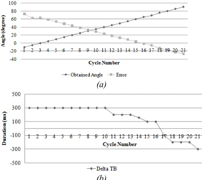
As mentioned before, error is defined as the difference between target angle and obtained angle. As shown in Figure 3(a), the value of error changed according to the obtained angle. The output of controller, ΔTB, was also shown in Figure 3(b). The burst duration remained steady at 300 ms until the 11th cycle where value of error started to reach 0 degree, meaning the obtained angle almost reach the target. It remained steady at 200 ms until the 13th cycle, then started to decrease continously until the end of the test. This is caused by the value of error that was also decreasing. It means the obtained angle reached the target angle but keep increasing in degree, resulting in further distance from the target. Controller reacted by decreasing the duration in order to bring the obtained angle closer to the target. As shown in Figure 3, the test result of SISO controller was compatible with the rules made in Table 1.
(a)
(b)
Figure 3: Result of Feasibility Test of SISO Controller: (a) Relation Between Obtained Angle and Error,
[image:4.612.314.520.512.695.2](a)
[image:5.612.92.297.71.286.2](b)
Figure 4: Result of Feasibility Test of MISO Controller: (a) Relation Between Obtained Angle, Error, and Desired
Range, (b) Value of ΔTB
The same pattern was shown in the test result of MISO controller. As indicated in Figure 4(a), the value of error and desired range, both used as input for the controller, changed according to the angle obtained. Error had opposite value from obtained angle according to the difference between target angle and obtained angle. But on the other hand, desired range gave a linear value with obtained angle.
The results of test for both controllers showed that the controllers worked well according to the fuzzy rules made. The output matched with input given and as the result, the value of ΔTB was produced accordingly.
3.2 Tests on Neurologically Intact Subject
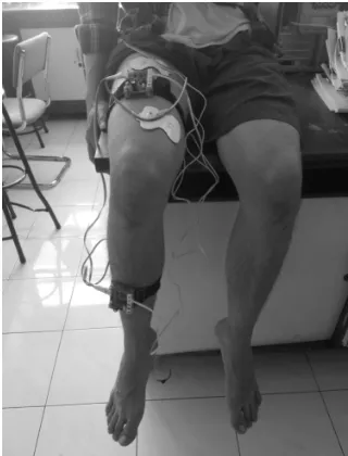
The next test was done with 10 neurologically intact subjects (male, 21-25 y.o). The test was divided into two sections: knee flexion and knee extension movements. Subject was asked to sit comfortably so that the knee of subject could move freely as shown in Figure 5. Before the test, the aim and procedure were explained to the subject and subject’s consent was obtained.
Frequency and pulse width for stimulation pulse were set for 20 Hz and 200 µs, respectively. Sampling interval was set for 10 ms. The test for each section was done in two trials, with each trial consisted of 30 stimulation cycles. Stimulation period for each cycle was set for 5 s, and initial burst duration for each section was set for 0 ms.
3.2.1 Test on Maximum Knee Flexion
Control
The test for maximum knee flexion control was done by giving stimulation to Biceps Femoris Long Head (BFLH) muscle.
The result was evaluated using two paramaters, which were Settling Index (SI) and RMSE. SI was defined as the number of cycle needed to achieve 5% of target angle. The test result was shown in Table 3.
The result showed that SI for all subjects was under 10 cycles, except for two trials of Subject D and H. Furthermore, first trial of Subject C and second trial of Subject G could not achieve the target angle for all cycles. RMSE for all subjects was under 2o, except first trial of Subject C.
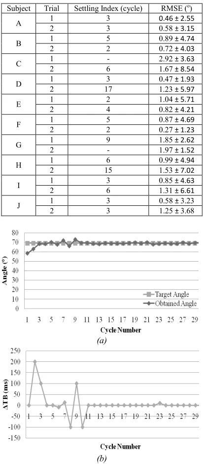
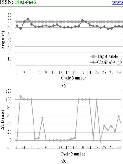
The control result of first trial for Subject A was shown in Figure 6. Burst duration was controlled well by fuzzy controller through the stimulation. Subject was able to achieve the target angle in three cycles, with small oscillation happened in the 6th until 9th cycle.
[image:5.612.337.497.478.688.2]The value of ΔTB was shown in Figure 6(b). The controller regulated burst duration in early cycles by both increasing and decreasing the duration of stimulation. After knee joint was able to achieve the target angle, from the 11th cycle onward controller didn’t change the duration time. In other word, the value of ΔTB was zero to maintain flexion angle achieved by knee joint. The controller was able to control burst duration well so that knee joint could achieve target angle continously.
Table 3: Evaluation Parameter of Maximum Knee Flexion Control Test
Subject Trial Settling Index (cycle) RMSE (o)
A 1 3 0.46 ± 2.55
2 3 0.58 ± 3.15
B 1 5 0.89 ± 4.74
2 2 0.72 ± 4.03
C 1 - 2.92 ± 3.63
2 6 1.67 ± 8.54
D 1 3 0.47 ± 1.93
2 17 1.23 ± 5.97
E 1 2 1.04 ± 5.71
2 4 0.82 ± 4.21
F 1 5 0.87 ± 4.69
2 2 0.27 ± 1.23
G 1 9 1.85 ± 2.62
2 - 1.97 ± 1.52
H 1 6 0.99 ± 4.94
2 15 1.53 ± 7.02
I 1 3 0.85 ± 4.63
2 6 1.31 ± 6.61
J 1 3 0.58 ± 3.23
2 3 1.25 ± 3.68
(a)
(b)
Figure 6: The Result of Maximum Knee Flexion Control (Subject A, first trial): (a) Value of Target Angle and
Obtained Angle, (b)Value of ΔTB
3.2.2 Test on Maximum Knee Extension
Control
The second test for knee extension control was done by giving stimulation to Vastus Medialis and/or Rectus Vemoris muscles. The same evaluation parameters as knee flexion control test was used as shown in Table 4.
SI for all subjects was under 10 cycles, except the first trial of Subject C and second trial of Subject J. There were also cases where subject could not achieve the target angle all throughout the test, like in both trials of Subject A and F. RMSE for all subjects was under 5o, except the first trial of Subject A with RMSE bigger than 5o.
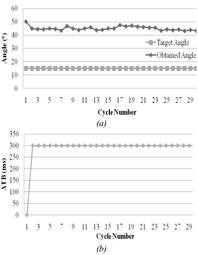
[image:6.612.312.526.359.719.2]It is shown from Figure 7 that burst duration for the first trial of Subject J was controlled well by fuzzy controller. Subject was able to reach target angle after three cycles and continously did so. Through the test, knee joint was able to reach the target in a stable manner. Figure 7(a) showed that burst duration was regulated in early cycles by increasing and then decreasing it. After the target angle was achieved in the third cycle, controller only did little change in burst duration value. It can be shown by the value of ΔTB that was almost zero for the rest of the trial. By doing so, the knee angle could be maintained well until the end of the test.
Table 4: Evaluation Parameter of Maximum Knee Extension Control Test
Subject Trial Settling Index(cycle) RMSE (o)
A 1 - 5.51 ± 1.55
2 - 3.07 ± 17.57
B 1 6 2.53 ± 13.09
2 6 2.65 ± 14.00
C 1 10 2.11 ± 8.94
2 8 2.11 ± 8.77
D 1 9 4.42 ± 14.44
2 14 4.98 ± 13.57
E 1 4 1.81 ± 9.78
2 8 1.71 ± 8.92
F 1 - 4.11 ± 7.48
2 - 3.40 ± 10.20
G 1 7 2.09 ± 10.95
2 7 2.07 ± 11.16
H 1 4 1.86 ± 9.92
2 6 1.80 ± 9.47
I 1 3 1.55 ± 8.33
2 3 1.05 ± 5.81
J 1 3 1.68 ± 9.05
2 18 2.65 ± 11.68
(b)
Figure 7: The Result of Maximum Knee Extension Control (Subject J, first trial): (a) Value of Target Angle
and Obtained Angle, (b)Value of ΔTB
3.3 Inability to Reach Target Angle and Muscle
Fatique
In both tests, there were cases where subject wasn’t able to reach target angle throughout the test. In maximum knee flexion control test, the first trial of Subject C and second trial of Subject G both resulted in this case. In maximum knee extension control test, both trial for Subject A and Subject F showed that the subject wasn’t able to achieve target angle for 30 cycles. The result of first trial of Subject C for knee flexion control test and second trial of Subject A for knee extension control test are shown in Figure 8 and 9, respectively.
Another phenomenon occured during the test was muscle fatigue. It is defined as condition where obtained angle decreasing and muscle wasn’t able to achieve target angle again continously. As shown in Figure 10, the burst duration in the second trial of Subject J was controlled well until the fifth cycle. Then from the sixth cycle, obtained angle dropped until 7,7 degree from target angle of 69 degree. Controller was able to overcome it by increasing burst duration, therefore in the twelfth cycle, knee flexion angle reached 64,9 degree. But then obtained angle continu to drop until the eighteenth cycle. In the nineteenth and twentieth cycle, obtained angle was able to be stabilized around 71,8 degree and then dropped again until the end of the test.
In the second trial of Subject J, maximum error resulted was 9,1 degree in the sixteenth cycle. Muscle fatigue is assumed to be compensated if absolute error is less or equal with Δθ. Recovery index is defined as number of cycle required to compensate muscle fatigue. In this case, 13 cycles was needed to compensate the fatigue.
(a)
[image:7.612.315.515.387.644.2](b)
Figure 8: The Result of Maximum Knee Flexion Control (Subject C, first trial): (a) Value of Target Angle and
Obtained Angle, (b)Value of ΔTB
(a)
(b)
Figure 9: The Result of Maximum Knee Extension Control (Subject A, second trial): (a) Value of Target
(a)
[image:8.612.91.291.75.341.2](b)
Figure 10: The Result of Maximum Knee Flexion Control (Subject J, second trial): (a) Value of Target Angle and
Obtained Angle, (b)Value of ΔTB
4. DISCUSSION AND CONCLUSION
4.1 Discussion
A system of wearable functional electrical stimulation system for knee joint movement was designed and realized. Tests with neurologically intact subjects showed that the controllers designed were effective in adjusting burst duration of stimulation. In both test for knee flexion and knee extension movement, the joint angle could be controlled well. The trials for maximum knee flexion resulted in RMSE less than 7 degree and SI of 2-10 cycles. RMSE for maximum knee extension control test was less than 5 degree with SI of 3-10 cycles.
Since the initial burst duration was set to 0 ms, the controller increased the burst duration in earlier cycle before reaching the target angle. Once the target angle was achieved, the controller managed the burst duration to keep the tilt angle of knee joint. The burst duration was also adjusted if there were change in the obtained angle. This adjustment comprised of two actions: decreasing and increasing the burst duration. The duration would be decreased if the obtained angle was larger than target and it would be increased if obtained angle was smaller than the target.
In some trials, the stimulation given was not able to help knee joint to achieve the desired result. A movement was indeed produced, but it did not reach the target angle. In this case, the physical proportion of the subject and the electrode placement had important role. The physical conditon and activity (i.e. physical exercise) of the subject also affect the outcome of stimulation.
Muscle fatigue also happened in some trials. It basically caused by recruitment method used by FES to produce muscle contraction. FES uses synchronous recruitment, different with intact central nervous system (CNS) which uses asynchronous recruitment. By using this method, FES is required to use higher stimulation frequency compared to the one produced by intact CNS. It resulted in the increasing chance of muscle fatigue happening during electrical stimulation. Therefore, for FES system, a controller with adjustment ability is needed.
4.2 Conclusion
In this study, a wearable functional electrical stimulation system was designed and realized to accommodate knee joint movement. The system consists of sensor system, electrical stimulator, and fuzzy logic controller.
As shown by the tests result of knee joint movements with neurologically intact subjects, the controllers were able to adjust burst duration of stimulation. The decreasing muscle force caused by muscle fatigue in the tests was also able to be compensated well by the controllers designed. The use of cycle-to-cycle control ensured that the controller adjusted the stimulation according to knee angle in each cycle.
In order to realize a wearable FES aid, a complete lower limb FES system will be the focus of future research. The use of EMG and test on subject with paralysis are also considered to obtained better result of muscle condition and response of subject.
ACKNOWLEDGMENT
REFERENCES:
[1] C. L. Lynch and M. R. Popovic, “Functional Electrical Stimulation: Closed-Loop Control of Induced Muscle Contractions”, IEEE Control
Systems Magazine, April 2008, pp. 40-50.
[2] Christopher and Dana Reeve Foundation.
(2013). [Online]. Available:
https://www.christopherreeve.org/living-with-paralysis/stats-about-paralysis
[3] B. M. Doucet, A. Lam, and L. Griffin, “Neuromuscular Electrical Stimulation for Skeletal Muscle Function”, Yale J Biol Med, 2012, 85(2): 201 – 215.
[4] C. L. Lynch, G. M. Graham, and M. R. Popovic, “Including non-ideal Behavior in Simulations of Functional Electrical Stimulation Applications”, Artificial Organs, 35(3): 267 – 269, 2011.
[5] A. Arifin, T. Watanabe, and N. Hoshimiya. “Design of Fuzzy Controller of the Cycle-to-cycle Control for Swing Phase of Hemiplegic Gait Induced by FES”, IEICE Trans. INF &
SYST., Vol. E89-D, No.4, April 2006.
[6] T. Watanabe, T. Masuko, and A. Arifin, “Preliminary Tests of A Practical Fuzzy FES Controller Based on Cycle-to-Cycle Control in The Knee Flexion and Extension Control”,
IEICE Transactions of Information and
Systems, Vol. E92-D, No. 7, July 2009,
pp.1507-1510.
[7] N. Miura, T. Watanabe, S. Sugimoto, K. Seki, and H. Kanai, “Fuzzy FES Controller Using Cycle-to-Cycle Control For Repetitive Movement Training in Motor Rehabilitation. Experimental Tests With Wireless System”,
Journal of Medical Engineering and
Technology, Vol. 35, No. 6-7, 2011, pp.
314-321.
[8] B. S. K. K. Ibrahim, M. O. Tokhi, M. S. Huq, and S. C. Gharooni, “Fuzzy Logic Based Cycle-to-Cycle Control Of FES-Induced Swinging Motion”, International Conference
on Electrical, Control and Computer
Engineering, June 2011.
[9] S. Z. Yahaya, Z. Hussain, I. Isa, R. Boudville, M. F. A. Rahman, M. N. Taib, “Cycle to Cycle Control in FES-Assisted Elliptical Stepping Exercise”, Proceedings of IEEE EMBS Conference on Biomedical Engineering and
Sciences, Kuala Lumpur (Malaysia), December
4-8, 2016, pp. 737-741.
[10]A. L. Basith, A. Arifin, F. Arrofiqi, T. Watanabe, and M. Nuh, “Embedded Fuzzy Logic Controller for Functional Electrical Stimulation System”, Proceedings of
International Seminar on Intelligent
Technology and its Applications (ISITIA),
Intitut Teknologi Sepuluh Nopember (Indonesia), July 28-30, 2016, pp. 89-94. [11] F. Arrofiqi, A. Arifin, and B. Indrajaya,
“Design of Wearable System for Closed-loop Control of Gait Restoration System by Functional Electrical Stimulation”,
Proceedings of International Seminar on Intelligent Technology and its Applications
(ISITIA), Intitut Teknologi Sepuluh Nopember