A TEXT-BASED IMPLEMENTATION MODEL FOR
REUSABLE ASPECT MODELS
ABID MEHMOOD, DAYANG N.A. JAWAWI
Department of Software Engineering, Faculty of Computing, Universiti Teknologi Malaysia (UTM)
Email: [email protected], [email protected]
ABSTRACT
Model-Driven Engineering utilizes modeling to provide abstraction techniques in order to effectively manage the complexity inherent in software systems development for a problem domain. Further, it emphasizes the use of models as primary development artifacts, and encourages researchers and professionals to develop ways that can lead to obtaining executable systems from models. Reusable Aspect Models is a multi-view modeling approach, which combines existing aspect-oriented approaches to modeling class, sequence and state diagrams, into a single approach. These models can serve as an effective design notation to provide abstraction for a given domain. Moreover, these models may be used as input to a model-driven engineering process to obtaining an executable system, by transforming them into aspect-oriented code. However, when investigating different ways of transforming models into code, an important technical issue is to determine a formal (and semantically equivalent) computer-understandable, text-based implementation of the graphical model. Here, a text-based model for Reusable Aspect Models has been presented. To make sure that the text-based model captures all relevant concepts of the notation, a conceptual reference model for Reusable Aspect Models has been presented first, and later implemented through the use of XML schemas.
Keywords: Aspect-Oriented Modeling, Code Generation, Model-Driven Engineering
1. INTRODUCTION
Aspect-oriented software development (AOSD) techniques [1-3] improve the handling of crosscutting concerns, which cut across the primary modularization of a system, by providing means to identifying, modeling, and implementing them independent of each other as well as isolated from the non-crosscutting concerns of a system. Aspect orientation is applied at all levels of software development, for example, Early Aspects [1] are used during the analysis phase, whereas Aspect-Oriented Modeling (AOM) [2] are used at the design level, and Aspect-Oriented Programming (AOP) [3] languages are used for implementation of aspect-oriented software. In the context of Model-Driven Engineering (MDE)[4], which makes use of design models as the primary artifact to generating an executable system, the AOM notations can be used to obtain an aspect-oriented implementation of systems through automated, or semi-automated ways.
Reusable Aspect Models (RAM) [5-8] is a multi-view modeling approach that unifies existing aspect-oriented approaches to model class, sequence and state diagrams into a single approach. Multi-view modeling enables
designers to use different modeling notations to describe a system from multiple points of view. In this way, a modeler can make choice of an appropriate modeling notation to describe different views of the system. RAM can be distinguished from other AOM notations in the sense that it models any reusable functionality in a system by means of an aspect. Hence, different views (i.e., structure, message, and state views) of a reusable concern are encapsulated in the form of an aspect model. This model takes the form of a special UML package, and comprises of three different compartments, representing the structural view, state view and message view. These views are expressed using a UML class diagram, state diagram and sequence diagrams, respectively.
The Object Management Group (OMG) 1 has developed a number of specifications to facilitate the software application development. In order to support MDE, the OMG provides the Model-Driven Architecture (MDA)2, which is an approach that utilizes modeling to provide abstraction techniques to effectively manage the
1
www.omg.org
complexity inherent in software systems development for a problem domain. RAM models can serve as an effective design notation to provide abstraction for a given domain [5, 9]. Further, these models may be used as input to an MDE process to obtaining an executable system, by transforming them into aspect-oriented code [10]. A detailed discussion on the benefits associated with model-driven code generation can be found in [11-15]. However, when we transform a graphical model (e.g., one developed using RAM notation) into code, an important technical issue is to determine a formal and semantically equivalent text-based implementation of the graphical model. This is essential because the code generation system needs a computer-understandable representation of the graphical model. Conventionally, model-driven code generation approaches have used Extensible Markup Language (XML) and related standards to define text-based implementation models, see for example [15-18]. However, unless XML documents adhere to a certain degree of representation rigor, their transformation procedures may need to be updated each time the model is updated. Further, if different applications implement this transformation differently, the data (i.e. objects) represented within XML cannot be easily exchanged among applications. Consequently, OMG has set-forth an important standard to link this transformation with the MDA context, i.e., the Extensible Metadata Interchange (XMI) [19]. XMI is the part of MDA that essentially provides a standard way of representing different model elements and objects using XML. In practice, it can be used to generate XML schemas, which define the content of XML documents, in a standard way. XML schemas are then used to generate and validate the corresponding XML documents.
In this paper, we propose a technique of transforming RAM models into XML schema, which can serve as the basis to generating text-based implementation models for RAM aspects. The paper is organized in six sections. Following this introduction, Section 2 highlights the motivation for this work and briefly describes some related work in the literature. Some background information on Reusable Aspect Models, XML and XML schema that was important in the context of this study, is presented in Section 3. Section 4 and Section 5 present the conceptual reference model and
implement the same using XML schema, respectively. Section 6 concludes the paper.
2. MOTIVATION AND RELATED WORK
Model-driven code generation significantly enhances the software development by allowing rapid development of high quality code, reducing the number of accidental programming errors, and enhancing the consistency between design and code [11-15]. The use of aspect orientation is also known to carry certain positive effects on software development, see for example the evidence provided by Ali et al. [20] and the experience of Hovsepyan et al. [21]. Further reasoning on the use of aspect orientated techniques can be found in [22-25]. Owing to this, several approaches have appeared in the literature addressing model-driven code generation while making one of the aspect-oriented programming languages as the target platform. However, the idea of automatic code generation cannot be realized without defining a conceptual transformation of the graphical input model into a computer-understandable representation. This representation can take any form, for example, a custom-defined text file, a table etc., or it can preferably be defined in a
standard way, in order to support
rules for representation of model data (specifically corresponding to behavioral part) are not well-defined in the literature. Therefore, in this paper, we address this need and define a standard way of transforming RAM models into XML schema.
Existing work in the broader context of this study can be perceived under two different categories. The work in the first category focuses only on the generation of code from a given model, and the XML-based representation is used as an intermediate representation. This category is more inclined to implementation, and thus, it does not provide much detail on the design decisions behind transforming model at one level to another. In this regard, Bennett et al. [16] have defined an XML schema to provide a text-based representation of aspects developed in Formal Design Analysis Framework (FDAF) [27]. FDAF works at architectural design level; hence the schema covers no details of the detailed design process. It is limited to handling of the crosscutting nature of an aspect by providing means to contain an advice and a pointcut, and it covers no details of the structure or behavior of aspect itself. Similarly, Hecht et al. [28] have defined a schema to represent Theme/UML [29] models in text-based format and used this representation in an XMI-based code generator. Just like the previously discussed work, they have not illustrated a general-purpose mapping. Rather, they have defined two new elements into the basic structural representation of Theme/UML model in XMI. One of these elements refers to the model elements that can be bound to actual classes during a composition, whereas the other defines the composition. They
use Extensible Stylesheet Language
Transformation (XSLT) for code generation. Apart from the fact that the use of XSLT for this purpose has been reported to have certain limitations (see [30]), their approach makes the schema very specific to their implementation, and hence it cannot be used or extended by other non-XSLT-based approaches.
As far as the work in the second category is concerned, several techniques have appeared in the literature to transform UML-based models into XML schemas. In this regard, Routledge et al. [31] have proposed a technique to mapping from UML class diagrams to XML schemas. They have defined a UML profile to correspond to different XML schema data structures. This approach, however, does not cover some of the
basic elements of UML, such as relationships and constraints. Similarly, Carlson’s work [32] has proposed a UML profile that addresses the mapping of package diagrams besides the class diagram, through an approach based on XMI rules. Some similar work in the area includes the work of Wu and Hsieh [33] and Conrad et al. [34]. However, all works in this category, apart from having some other limitations, focus on class (or some other structural) diagrams only. XML schema representation of behavioral diagrams has not been addressed. Further, these approaches do not generally integrate the schemas and the resulting text-based representation in the larger context of model-driven engineering. In contrast, our intention in this paper is to provide a representation of models developed using Reusable Aspect Models approach, including the structural and behavioral representations. Since the effectiveness of Reusable Aspect Models approach has been shown in the literature using certain non-trivial modeling case studies [5, 9, 35, 36], we believe that our textual representation of models can be valuable to textually represent any kind of application scenario. Further, this textual representation can be used by any kind of code generations systems that are capable of processing XML-based models.
3. BACKGROUND
3.1. Reusable Aspect Models
Complete classes are later produced by means of composition with other classes at the time of instantiation of the aspect. The incomplete classes are termed as mandatory instantiation parameters.
Following the structural compartment, one or more state view compartments correspond to the classes defined in structural view of the aspect model. State view contains UML state diagrams to describe the internal states of the class that are relevant within the concern. For complete classes (i.e., standard classes) in the structural view, the state diagram will be a standard state diagram. However, for incomplete classes, in which concerns are to be injected later, an aspectual state diagram is defined which contains two parts: a pointcut and an advice. The pointcut part is used to define the states and transitions that are required in target state diagram, whereas the state diagram that replaces the occurrence of pointcut in the target state diagram is defined by the advice part.
Aspect models are used in a target model by means of either instantiation or binding directives. Instantiation directives map the mandatory instantiation parameters defined in different views of the aspect model to elements in the target model. For example, an instantiation directive in structural view can be defined to assign one or more classes of the view to classes declared as mandatory instantiation parameters in some other aspect. Unlike instantiation directives, which are specific to incomplete classes, binding directives are used to bind complete classes or methods to other classes or methods.
3.2. XML and XML Schemas
XML has emerged as a powerful and easy-to-use standard to save and exchange data [30, 37]. It can easily be integrated with other related standards and tools which allow accessing the data stored in XML documents by means of standard application programming interfaces (APIs). XML represents the stored data using XML elements consisting of a start tag, XML attributes, content, and an end tag.
The structure and content of an XML document is defined using an XML schema[38]. Just like the rules and features of a UML diagram, XML schemas define a set of rules describing elements and other markup objects to be defined in an XML document. The standard to
define XML schemas is called XML Schema Definition (XSD).
4. THE CONCEPTUAL REFERENCE
MODEL FOR RAM
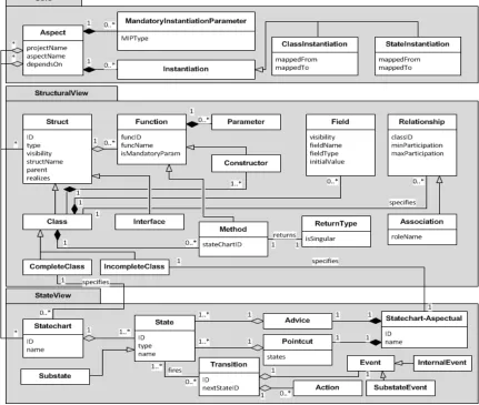
The Conceptual Reference Model (CRM) in this section defines the set of basic elements of a RAM model and their relationships with each other, which lead to a comprehensive representation of the designed system. We present the CRM in a graphical form using the notation of a UML class diagram and complement it with a textual definition of each concept defined in the class diagram. The essential purpose of this model is to elaborate the concepts used by a RAM model in a systematic way, so that the same elaborated definition can be used to propose a schema representation of the RAM models. It is important to note here that since our CRM has been defined in a generic way in terms of UML meta-classes, it can further be extended by defining subclasses to support more concepts of RAM models. Thus, for example, the support for sequence views of RAM can be provided by means of extending our CRM.
In the following, we illustrate the concepts of CRM along three major parts, i.e., Core, StructuralView and StateView, represented as a package, see Figure 1. The Core package covers the high level global details of the RAM aspect, whereas the StructuralView and StateView correspond to the structural and behavioral details of the aspect, respectively.
4.1. Core
The Core package contains the global details related to an aspect. On one hand, it contains the information on mandatory instantiation parameters as well as the specific instantiations as declared by the structural view. On the other hand, it specifies the aspect to contain the classes and statechart diagrams defined in structural and state views, respectively.
(StructuralView) whereas the state diagrams (StateView) and sequence diagrams are used for behavioral modeling. Note that we have used only the state diagrams in the current study because we consider them preferable to sequence diagram in terms of modeling behavior. Another reason for the use of state diagrams is that this paper intends to contribute to aspect models in the specific context of code generation, and state diagrams have been used to generate full behavioral code for objects (in contrast to their counterparts which mostly generate skeletons) [13]. A detailed discussion on advantages of state machines over sequence
and other behavioral diagrams can be found in Cottenier et al. [39], Vanderperren et al. [40] and Harel [41]. Further, the aspect defines mandatory instantiation parameters, which are model elements that must be composed with other (target) models by means of instantiation or binding. RAM models can declare a class, a specific instance of a class, a method of a class, or a state as a mandatory instantiation parameter (determined by MIPType).
Figure 1 The conceptual reference model for Reusable Aspect Models
An aspect can use the functionality provided by another aspect by declaring a dependency relationship with that aspect (dependsOn). In case an aspect is dependent on another aspect, it specifies some instantiation directives (in case it refers to incomplete elements) or binding
[image:5.612.90.521.265.630.2]and StateInstantiation in our CRM to correspond to these concepts. Each of the classes contains information specifying which element of the reused aspect (mappedFrom) is mapped to which element of the dependent aspect (mappedTo).
4.2. StructuralView
Conceptually, the structural view of an aspect defines a set of classes and interfaces, and their relationships with each other. In order to emphasize different concepts captured by the classes in the structural view of a RAM model, we have elaborated them in the StructuralView part of Figure 1. The CRM shows that both types of the basic structural units, i.e., Class and Interface share some conceptual characteristics captured in the general type Struct. However, a Class can either be complete (CompleteClass) or an incomplete one (IncompleteClass), in which case it is expected to be woven with some other class by means of binding or an export as a mandatory instantiation parameter. Both types of Struct may contain an arbitrary number of functions (Function). However, the specialized types of Constructor and Method can only be contained by classes, where the former refers to constructors of classes and the latter to functions which are associated with a statechart given in the state view. Therefore, an instance of Method always contains a reference to the statechart which defines its behavior (stateChartID). Unlike constructors, instances of Method also specify some return type (ReturnType). The attribute isSingular in ReturnType takes care of the cases in which a method returns an enumeration or collection of some type of objects. Classes also contain fields (Field).
A class in RAM model may specify how it is conceptually related to other classes in the model (Relationship). It also specifies the multiplicity of relationship (minParticipation, maxParticipation) with the class on other end of the relationship (classID). In the specific case of association relationship, in which the roles of participants on either side of the relationship are relevant, we take care of the role name (roleName in Association).
4.3. StateView
From a conceptual standpoint, the state view of an aspect model defines the behavior of some of the classes given in the structural view. However, since there are two different types of classes that can exist in the aspect models, i.e., complete and incomplete classes, we may distinguish between two different ways to
specifying the behavior of each type. One way, which is applicable to complete classes, is to associate a standard statechart diagram (Statechart) with the class. Other way, which essentially applies to incomplete classes, is to associate an extension of the state diagram (Statechart-Aspectual) that contains special constructs related to aspect-oriented concepts.
An instance of Statechart may contain an arbitrary number of states (State). Each state in the state diagram may fire a transition (Transition) which can essentially be seen as a combination of an event to be triggered (Event) and an associated action (Action). A state may be defined as a composite state and thus may contain other states (Substate).
An object of Statechart-Aspectual type is conceptually different from a standard statechart in the sense that it contains a pair of a pointcut (Pointcut) and an advice (Advice). Pointcut defines all the states which are relevant in order to fulfill some functionality defined by the state diagram, and in turn, the aspect. Advice, on the other hand, defines the states and their respective transitions to occur in case the pointcut was matched. The State and Transition types are semantically equivalent to those described previously for a standard statechart.
5. THE TEXTUAL IMPLEMENTATION
MODEL
In this section, we present the text-based implementation model developed for Reusable Aspect Models in the form of XML schema. The schema is based on the conceptual reference model described in the previous section, and it employs the same design principles which we applied to define the CRM. It has to be noted here that the schema proposed in this section is a generic representation of RAM models, and that it can be used in combination with any other standard, such as XMI.
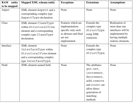
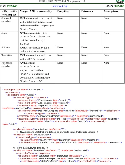
An overview of the specification of mapping from RAM models to XML is presented in TABLE 1. In the following, we take the RAM conceptual entities identified through the CRM, one by one, and illustrate how they can be implemented by means of the XML schema. It is to be noted here that the RAM aspect described in section 5.1 serves as the main encapsulating entity and implements the Core of the CRM. Following this, sections 5.2 through 5.6 are related to the
sections 5.7 through 5.11 define the concepts defined in StateView of the CRM.
5.1. RAM aspect
RAM aspect, which encapsulates all other modeling units existing in a RAM model, is implemented by defining an XML element (<xs:element>) named Aspect and an associated complex type declaration (<xs:complexType>) named AspectType in XML schema. The Aspect element appears as the root element and all such elements of
AspectType are capable of containing all the
constructs related to structural and state views of an aspect, as applicable to specification of RAM aspect models. A partial XML schema is shown in Figure 2, which represents the AspectType.
Aspect element further contains three elements
Core, StructuralView and optionally
StateView that correspond to three main
segments of the CRM described in Section 4.
The Core contains five elements for which a brief description follows. ProjectName and
AspectName elements are of string type
(<xs:string>) and refer to names of the project that uses this aspect and the aspect itself, respectively. These elements are followed by declaration of an element dependsOn which actually lists the names of any number aspects this aspect is dependent on, using a sub-element named dependsOnAspect. RAM aspects are not required to be dependent on other aspects but they may define any number of dependencies,
therefore, the minOccurs value of
dependsOn is set to 0 whereas the
maxOccurs is set to unbounded. Further, by
setting the values of minOccurs of
dependsOnAspect to 1 and maxOccurs to
unbounded, the schema actually requires that
in case dependsOn was declared, it must define at least one dependesOnAspect element. Next within the Core element, we declare a
mandatoryInstParam element, which will
[image:7.612.90.528.392.733.2]be described in detail in Section 5.5.
Table 1: Overview of mapping from RAM aspect models to XML schema
RAM entity to be mapped
Mapped XML schema entity Exceptions Extensions Assumptions
Aspect XML element Aspect and a corresponding complex type
AspectType declaration.
None None None
Class XML element ClassType
within StructuralView element and a corresponding complex type ClassType declaration.
Features which are implementation- specific only such as abstract and final are not
implemented.
Extends the complex type StructType using XML extension.
Realization of more than one interfaces will be implemented by having multiple realizes elements.
Interface XML element
InterfaceType within
StructuralView element
and a corresponding complex type InterfaceType.
None Extends the
complex type
StructType.
None
Field XML element named field. None The attributes get, set,
increment,
decrement,
add, remove
and count can allow direct generation of matching methods.
RAM entity to be mapped
Mapped XML schema entity Exceptions Extensions Assumptions
Constructor XML element constructor within ClassType element along with a complex type
Constructor.
Default
constructors are not implemented in schema.
Extends the generic
FunctionTyp e.
The funcName
element of FunctionTyp e is applicable to determine the object type directly. Method XML element operations within
ClassType element along
with the complex type
Method.
None Extends the
FunctionTyp e by associating optional values of return type and statechart ID.
For void return types, we omit the element.
Similarly, if there is no statechart ID, we assume it as an unstated method, for which skeletons can be directly added. Mandatory
instantiation parameter
XML element
mandatoryInstParam declared within Core element
of AspectType.
None The type
attribute determines different types such as class, method, field etc.
None
Instantiation/ binding directive
XML element
Instantiations within
Core element of
AspectType.
None Instantiation and
binding directives in structural view are implemented within
ClassInst element, whereas, those in state view are implemented within
StateInst element.
None
Relationship • For inheritance, XML element parent within
ClassType element.
• For association, XML element association along with declaration of a complex type
AssociationType.
• For aggregation and composition, XML elements aggregation
and composition
along with declaration of matching complex type
RelationshipType.
None None Other possible
relationship type extensions may be implemented using
RAM entity to be mapped
Mapped XML schema entity Exceptions Extensions Assumptions
Standard statechart
XML element statechart within StateView element and corresponding complex type
StateChart.
None None None
State XML element state within
statechart element and
matching complex type State.
None None None
Substate XML element substate within state element.
None None None
Transition XML element transition within state element.
None None None
Aspectual statechart
XML element
statechart-aspectual within
StateView element and
declaration of matching type
StateChart-AO.
[image:9.612.90.524.61.634.2]None None None
Figure 2: An excerpt of XML schema for AspectType to represent a high level RAM aspect.
StructuralView element within Aspect
element contains the structural definition of the aspect as per the RAM specification.
StateView element contains the behavioral
description of the aspect. We defer a detailed discussion of these two elements to the following sections, wherein various conceptual constructs
related to each of these elements will be discussed.
5.2. Classes and interfaces
The classes and interfaces in structural view of a RAM aspect are implemented by having them stem from a common origin defined as Struct.
<xs:complexType name="AspectType">
<xs:sequence>
<xs:element name="Global">
<xs:complexType><xs:sequence>
<xs:element name="ProjectName" type="xs:string"/>
<xs:element name="AspectName" type="xs:string"/>
<xs:element name="DependsOn" minOccurs="0"
maxOccurs="unbounded"><xs:complexType><xs:sequence>
<xs:element name="DependsOnAspect" type="xs:string" maxOccurs="unbounded"/></xs:sequence>
</xs:complexType></xs:element>
<xs:element name="MandatoryInstParam" minOccurs="0" maxOccurs="unbounded">
<xs:complexType><xs:attribute name="MIPType"><xs:simpleType><xs:restriction base="xs:string">
<xs:enumeration value="class"/><xs:enumeration value="method"/><xs:enumeration
value="state"/>
…..
<xs:element name="Instantiations" minOccurs="0">
<!-- ClassInst and StateInst are defined as elements within Instantiations here -->
<xs:element name="StructuralView">
<xs:complexType><xs:sequence>
<xs:element name="ClassType" type="ClassType" maxOccurs="unbounded"/>
<xs:element name="InterfaceType" type="InterfaceType" minOccurs="0" maxOccurs="unbounded"/>
…..
<!-- Here, StateView is defined. -->
<xs:element name="StateView" minOccurs="0" maxOccurs="unbounded">
<xs:complexType><xs:sequence>
<xs:element name="statechart" type="StateChart" minOccurs="0"/>
<xs:element name="statechart-aspectual" type="StateChart-AO" minOccurs="0"/></xs:sequence>
The Struct is defined as an element that is associated with a composite type StructType.
The StructType essentially provides a
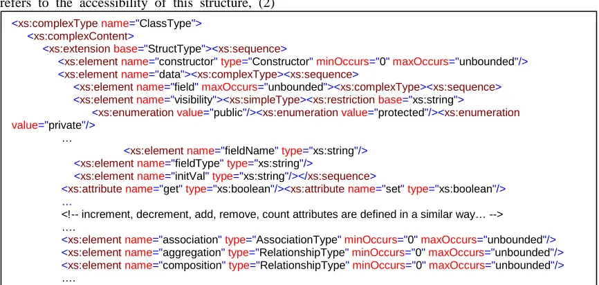
common structure which is shared by both structural units in RAM aspects, i.e., classes and interfaces. Specifically, it defines a number of elements to describe the properties of this structure including: (1) visibility which refers to the accessibility of this structure, (2)
structName which defines the name of this
[image:10.612.90.523.193.399.2]structure, (3) an optional element parent which specifies generalization relationship of this structure with other structures, (4) a number of optional elements named realizes which specify if this structure implements some of the existing interfaces.
Figure 3: An excerpt of XML schema for ClassType.
Further, Struct defines an optional element named operations (with maxOccurs set to
unbounded), which declares any number of
functions into structure. Details of functions will be presented in Section 5.4. Interfaces are implemented by means of adding an element
InterfaceType along with declaration of an
associated type named InterfaceType which extends the StructType.
So far as classes are concerned, they are implemented in a similar way by defining an element named ClassType and declaring an associated type named ClassType which extends StructType, see Figure 3. However, as in contrast with interfaces, classes bear some unique characteristics, they are implemented by adding a few more elements to the extension. These elements are: (1) data which is discussed in Section 5.3 (2) constructor which is described in Section 5.4, (3) association,
aggregation and composition which are
all related to the discussion in Section 5.6.
5.3. Fields
Fields define the attributes of classes in a RAM aspect’s structural view. We implement fields by defining a required element field with maxOccurs set to unbounded within data element of ClassType. The declaration of
field element is shown in Figure 3. The
field element contains a number of attributes
to support automatic generation of simple methods which may be associated with the fields. These attributes are: (1) get and set, which specify whether a getter and/or setter method is desired for this field, (2) increment and
decrement, which are specific to integer-type
fields and specify the possibility of generation of simple increment and/or decrement operations for the integer field, (3) add, remove and
count, which indeed work specifically for
fields of enumeration type and are intended to support the automatic addition of methods to add/ remove elements to the enumeration and return the number of elements in the enumeration.
As far as elements within the field element are concerned, there are four different elements of
<xs:complexType name="ClassType">
<xs:complexContent>
<xs:extension base="StructType"><xs:sequence>
<xs:element name="constructor" type="Constructor" minOccurs="0" maxOccurs="unbounded"/>
<xs:element name="data"><xs:complexType><xs:sequence>
<xs:element name="field" maxOccurs="unbounded"><xs:complexType><xs:sequence> <xs:element name="visibility"><xs:simpleType><xs:restriction base="xs:string">
<xs:enumeration value="public"/><xs:enumeration value="protected"/><xs:enumeration
value="private"/>
…
<xs:element name="fieldName" type="xs:string"/>
<xs:element name="fieldType" type="xs:string"/>
<xs:element name="initVal" type="xs:string"/></xs:sequence>
<xs:attribute name="get" type="xs:boolean"/><xs:attribute name="set" type="xs:boolean"/> …
<!-- increment, decrement, add, remove, count attributes are defined in a similar way… --> ….
<xs:element name="association" type="AssociationType" minOccurs="0" maxOccurs="unbounded"/> <xs:element name="aggregation" type="RelationshipType" minOccurs="0" maxOccurs="unbounded"/> <xs:element name="composition" type="RelationshipType" minOccurs="0" maxOccurs="unbounded"/>
<xs:string> type which cover the details of a field declaration. These elements are
visibility, fieldName, fieldType and
initVal. The purpose of first three elements is evident from their names, whereas, the last one is intended to support specification of an initial value for a variable.
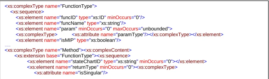
5.4. Methods and constructors
Just like interfaces and classes, we associate the methods and constructors to a common basis,
the FunctionType. The FunctionType
defines a number of essential properties applicable to both constructors of classes as well as methods, such as function name (funcName), any number of parameters (param), and a boolean value to specify whether this function is a mandatory instantiation parameter (isMIP).
[image:11.612.91.523.229.357.2]A method, however, is a special type of function which, unlike a constructor, specifies a return type. Return type of a method can either be a simple type or an enumeration.
Figure 4: Definition (partial) of FunctionType and the sub-type Method.
Our definition of a Method (shown in Figure 4) includes an element stateChartID which refers to the statechart which defines the behavior of this method. Since methods are not required to have statecharts define their behavior,
stateChartID element is optional. Further,
methods and constructors are defined in the structural view within operation and
constructor elements of Method and
Constructor types, respectively, in the
ClassType.
5.5. Mandatory instantiation parameters and instantiation directives
The concept of mandatory instantiation parameters, which makes it possible to combine various elements of an aspect model with those of a target model by means of instantiation and/or binding directives, is implemented by
introducing an element
mandatoryInstParam within Core of
Aspect (with minOccurs=0,
maxOccurs=unbounded) which defines all
parameters designated as required to be instantiated by a target model (see Figure 2). It contains an attribute (<xs:attribute>) MIPType to identify whether this parameter is a class, interface, method or a field etc. The last
element in the Core element is
Instantiations. This element corresponds
to the instantiation and binding directives defined in different compartments of the RAM aspect. Specifically, it defines two elements
ClassInst and StateInst. These elements
are defined with a minOccurs value of 1 and
maxOccurs value of unbounded, and they
list the instantiation and binding of model elements in the form of from-to pairs.
5.6. Relationships
We divide the relationships among various structural units of our model conceptually into three different types: (1) generalization or specialization, (2) realization, and (3) other relationships. Note that the support for (1) and (2) has been discussed in Section 0. Other relationships are implemented as follows.
There are three different forms of other instance-level relationships supported by our implementation, i.e., association, aggregation, and composition relationships. A new complex type has been defined with name
RelationshipType, which defines three new
elements classID, minParticipation,
and maxParticipation. The classID
refers to the ID of class on the other end of the relationship, whereas the other two elements define the minimum and maximum participation
<xs:complexType name="FunctionType"> <xs:sequence>
<xs:element name="funcID" type="xs:ID" minOccurs="0"/> <xs:element name="funcName" type="xs:string"/>
<xs:element name="param" minOccurs="0" maxOccurs="unbounded">
<xs:complexType> <xs:attribute name="paramType"/></xs:complexType></xs:element>
<xs:element name="isMIP" type="xs:boolean"/>
…..
<xs:complexType name="Method"><xs:complexContent> <xs:extension base="FunctionType"><xs:sequence>
<xs:element name="stateChartID" type="xs:string" minOccurs="0"></xs:element> <xs:element name="returnType" minOccurs="0"><xs:complexType>
of the declaring class in the relationship, respectively.
In order to implement aggregation and composition relationships, respective
aggregation and composition elements
are defined within the ClassType composite type (see Figure 3) and associated with the
RelationshipType simply. However, to
handle association relationship, we define an
element association of the
AssociationType, which extends
RelationshipType and assigns a role name
to the relationship by defining an attribute roleName on association.
5.7. Standard statechart
In our implementation, we differentiate between a standard statechart, which does not contain aspect-oriented constructs, and an aspectual statechart, which involves a pointcut and an advice. The support for aspectual statechart is discussed in Section 5.11. A standard statechart is implemented by
introducing a statechart element of
StateChart composite type into the
AspectType definition (see figure Figure 2).
The StateChart type essentially defines two
basic attributes id and name and a number of elements of State type (minOccurs set to 1)
which represent a state in the statechart. The
State element is further described in the
following section.
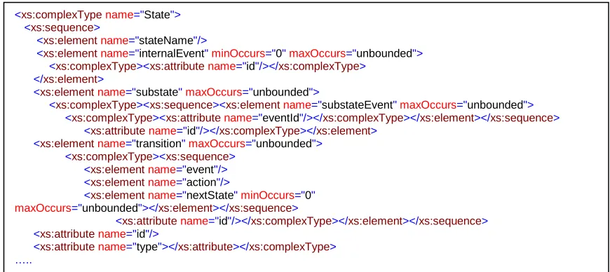
5.8. States
A statechart typically consists of more than one states and a number of transitions which determine the effect of certain events. We implement a state by defining a new complex type State and assigning a set of matching
state elements to it within the statechart
element (see Figure 5).
The State complex type defines two
attributes namely id and type. The id attribute provides a unique identification for this state, whereas, the type attribute is used to distinguish various types of states, i.e., actual, default and history states. Further, the State type defines four elements, i.e., stateName,
internalEvent, subState and
transition. The stateName refers to the
[image:12.612.88.523.455.649.2]name of this state. The internalEvent element is optional and may occur more than once to specify the name of action(s) associated with this particular state. The remaining two elements, i.e. subState and transition are described in the relevant discussion in sections 5.9 and 5.10, respectively.
Figure 5: XML schema representation of a State.
5.9. Substates
The subState element provides support for
the phenomenon of composite states which allows a state to have a number of substates [42].
We refer to the action to be carried in case of a substate transition by means of a
substateEvent element in a way similar to
state event, see Figure 5.
<xs:complexType name="State">
<xs:sequence>
<xs:element name="stateName"/>
<xs:element name="internalEvent" minOccurs="0" maxOccurs="unbounded">
<xs:complexType><xs:attribute name="id"/></xs:complexType> </xs:element>
<xs:element name="substate" maxOccurs="unbounded">
<xs:complexType><xs:sequence><xs:element name="substateEvent" maxOccurs="unbounded">
<xs:complexType><xs:attribute name="eventId"/></xs:complexType></xs:element></xs:sequence>
<xs:attribute name="id"/></xs:complexType></xs:element> <xs:element name="transition" maxOccurs="unbounded">
<xs:complexType><xs:sequence>
<xs:element name="event"/>
<xs:element name="action"/>
<xs:element name="nextState" minOccurs="0"
maxOccurs="unbounded"></xs:element></xs:sequence>
<xs:attribute name="id"/></xs:complexType></xs:element></xs:sequence>
<xs:attribute name="id"/>
5.10. Transitions
A transition in a state diagram is usually a combination of an event and a resulting action [42]. We implement transitions defined in state view of RAM models by introducing a new element named transition into the State type. The transition element essentially captures the concept of transition from this state (in which this element exists) to the next state. For this purpose, we define three elements within the transition element, i.e., event, action and
nextState. The semantics of these elements
are evident from their names and need no further explanation. However, there are two important points which need a brief note in the context of state transitions. First, since UML specification allows the event and action to take any form, we consider them as instance of string (<xs:string>) type in our implementation. As a result, they may contain, for instance, name of a method or only a conditional expression etc.
Second point is particularly relevant to the implementation of two advanced features of UML statecharts known as Fork and Join [42]. These features are in fact pseudostates, which are used to synchronize the transitions that enter into or leave a composite state [42]. Specifically, a fork refers to a transition that has one source state and two or more target states, whereas, a join represents a transition containing two or more source states and only one target state. Using our XML schema implementation, these two concepts will be implemented in a straightforward way. In particular, since the
nextState element contains the ID of the next
state, we will be having two IDs here in case of a fork, i.e., IDs of both states to be activated simultaneously. Similarly, in case of a join, two state elements will be having the same value for
nextState element.
5.11. Aspectual statechart
An aspectual statechart in RAM is an extension of a standard statechart that specifies the behaviors of a pointcut to be matched and a target advice to be executed in response. We implement an aspectual statechart by introducing
a new element named
statechart-aspectual in the state view of aspect, and
defining a new complex type StateChart-AO. Apart from defining two attributes id and name, which resemble in semantics to the attributes of standard statechart, a
StateChart-AO defines two new elements
namely pointcut and advice.
The pointcut element contains one or more
elements named state of string type. Note that the state element is not declared to be of the
State type because we need only the name of
states in the pointcut part. Further, the state element contains an attribute named type, which specifies whether this state is complete or incomplete state. Incomplete states are designated as mandatory instantiation parameters in RAM models.
The advice element contains one or more
elements of State type, which define states and their respective transitions as illustrated in sections 5.8 to 5.10.
6. CONCLUSIONS AND FUTURE WORK
In this paper, we have contributed a text-based implementation model for Reusable Aspect Models (RAM) notation. This model can serve as an intermediary between the graphical representation of RAM models and their implementation in a programming language. In this way, the current work is expected to effectively integrate the aspect models with the context of model-driven code generation, in a standard way.
In order to develop a comprehensive representation of RAM models, we have first defined a conceptual reference model which is presented in the form of UML class diagram. This model encapsulates all structural and behavioral concepts captured by RAM aspects in terms of their structural and state views. Later, we have developed a detailed mechanism of implementing the conceptual model by XML and related technologies, and have proposed an XML schema for this purpose.
REFERENCES:
[1] A. Rashid, A. Moreira, J. Araujo, P. Clements, E. Baniassad, and B. Tekinerdogan. (2006, Early aspects: Aspect-oriented requirements engineering and architecture design.
[2] T. Elrad, O. Aldawud, and A. Bader, "Aspect-Oriented Modeling: Bridging the Gap between Implementation and Design "
in Generative Programming and
Component Engineering. vol. 2487, D. Batory, C. Consel, and W. Taha, Eds., ed: Springer Berlin / Heidelberg, 2002, pp. 189-201.
[3] G. Kiczales, J. Lamping, A. Mendhekar, C. Maeda, C. Lopes, J.-M. Loingtier, and J. Irwin, "Aspect-oriented programming," in
ECOOP'97 — Object-Oriented
Programming. vol. 1241, M. Aksit and S. Matsuoka, Eds., ed: Springer Berlin / Heidelberg, 1997, pp. 220-242.
[4] "Proceedings of the 15th international conference on Model Driven Engineering Languages and Systems," Innsbruck, Austria, 2012, p. 826.
[5] J. Kienzle, W. Al Abed, F. Fleurey, J.-M. Jézéquel, and J. Klein, "Aspect-Oriented Design with Reusable Aspect Models," in Transactions on Aspect-Oriented Software Development VII. vol. 6210, S. Katz, M. Mezini, and J. Kienzle, Eds., ed: Springer Berlin / Heidelberg, 2010, pp. 272-320. [6] J. Kienzle, W. A. Abed, and J. Klein,
"Aspect-oriented multi-view modeling," presented at the Proceedings of the 8th ACM international conference on Aspect-oriented software development, Charlottesville, Virginia, USA, 2009.
[7] W. A. Abed and J. Kienzle, "Information Hiding and Aspect-Oriented Modeling," in Proceedings of the 14th Aspect-Oriented Modeling Workshop, Denver, CO, USA, 2009, pp. 1–6.
[8] J. Klein and J. Kienzle, "Reusable Aspect Models," presented at the 11th Workshop on Aspect-Oriented Modeling, Nashville, TN, USA, 2007.
[9] W. Al Abed and J. Kienzle, "Aspect-Oriented Modelling for Distributed Systems," in Model Driven Engineering Languages and Systems. vol. 6981, J. Whittle, T. Clark, and T. Kühne, Eds., ed: Springer Berlin / Heidelberg, 2011, pp. 123-137.
[10] M. Kramer and J. Kienzle, "Mapping Oriented Models to Aspect-Oriented Code," in Models in Software Engineering. vol. 6627, J. Dingel and A. Solberg, Eds., ed: Springer Berlin / Heidelberg, 2011, pp. 125-139.
[11] B. Karakostas and Y. Zorgios, Engineering Service Oriented Systems: A Model Driven Approach: IGI Global, 2008.
[12] M. Afonso, R. Vogel, and J. Teixeira, "From code centric to model centric software engineering: practical case study of MDD infusion in a systems integration company," in Model-Based Development of Computer-Based Systems and Model-Based Methodologies for Pervasive and Embedded Software, 2006. MBD/MOMPES 2006. Fourth and Third International Workshop on, 2006, pp. 10 pp.-134.
[13] E. Domı´nguez, B. Pérez, Á. L. Rubio, and M. a. A. Zapata, "A systematic review of code generation proposals from state machine specifications," Information and Software Technology, vol. 54, pp. 1045-1066, 2012.
[14] Ó. Pastor and S. España, "Full Model-Driven Practice: From Requirements to Code Generation," in Advanced Information Systems Engineering. vol. 7328, J. Ralyté, X. Franch, S. Brinkkemper, and S. Wrycza, Eds., ed: Springer Berlin Heidelberg, 2012, pp. 701-702.
[15] B. Lamancha, P. Reales, M. Polo, and D. Caivano, "Model-Driven Test Code Generation," in Evaluation of Novel Approaches to Software Engineering. vol. 275, L. Maciaszek and K. Zhang, Eds., ed: Springer Berlin Heidelberg, 2013, pp. 155-168.
[16] J. Bennett, K. Cooper, and L. Dai, "Aspect-oriented model-driven skeleton code generation: A graph-based transformation approach," Science of Computer Programming, vol. 75, pp. 689-725, 2010. [17] D. Kundu, D. Samanta, and R. Mall,
"Automatic code generation from unified modelling language sequence diagrams," Software, IET, vol. 7, pp. 12-28, 2013. [18] R. Pilitowski and A. Dereziñska, "Code
Engineering, T. Sobh, Ed., ed: Springer Netherlands, 2007, pp. 421-427.
[19] OMG, "MOF 2.0/XMI Mapping, Version 2.1.1," ed, 2007.
[20] M. S. Ali, M. A. Babar, L. Chen, and K.-J. Stol, "A systematic review of comparative evidence of aspect-oriented programming," Inf. Softw. Technol., vol. 52, pp. 871-887, 2010.
[21] A. Hovsepyan, R. Scandariato, S. V. Baelen, Y. Berbers, and W. Joosen, "From aspect-oriented models to aspect-oriented code?: the maintenance perspective," presented at the Proceedings of the 9th International Conference on Aspect-Oriented Software Development, Rennes and Saint-Malo, France, 2010.
[22] J. Hannemann and G. Kiczales, "Design pattern implementation in Java and aspectJ," SIGPLAN Not., vol. 37, pp. 161-173, 2002.
[23] A. Garcia, C. Sant'Anna, E. Figueiredo, U. Kulesza, C. Lucena, and A. v. Staa, "Modularizing design patterns with aspects: a quantitative study," presented at the Proceedings of the 4th international conference on Aspect-oriented software development, Chicago, Illinois, 2005. [24] L. Fuentes and P. Sánchez, "Execution of
Aspect Oriented UML Models," in Model Driven Architecture- Foundations and Applications. vol. 4530, D. Akehurst, R. Vogel, and R. Paige, Eds., ed: Springer Berlin / Heidelberg, 2007, pp. 83-98. [25] N. Cacho, C. Sant'Anna, E. Figueiredo, A.
Garcia, T. Batista, and C. Lucena, "Composing design patterns: a scalability study of aspect-oriented programming," presented at the Proceedings of the 5th international conference on Aspect-oriented software development, Bonn, Germany, 2006.
[26] T. J. Grose, G. C. Doney, and S. A.
Brodsky, Mastering XMI: Java
Programming with XMI, XML and UML: Wiley, 2002.
[27] L. Dai, "Formal design analysis framework: An aspect-oriented architectural framework," Ph.D. 3224352, The University of Texas at Dallas, United States -- Texas, 2005.
[28] M. V. Hecht, E. K. Piveta, M. S. Pimenta, and R. T. Price, "Aspect-oriented Code Generation," presented at the XX Brazilian
Conference on Software Engineering, 2005.
[29] S. Clarke and E. Baniassad, Aspect-Oriented Analysis and Design: The Theme Approach: Addison Wesley Object Technology, 2005.
[30] WWWC, "Extensible Markup Language (XML) 1.0 (fourth edition)," ed: World Wide World Consortium. Available at: http://www.w3.org/TR/xml/, August 2006 [Online].
[31] N. Routledge, L. Bird, and A. Goodchild, "UML and XML schema," Aust. Comput. Sci. Commun., vol. 24, pp. 157-166, 2002. [32] D. Carlson, Modeling Xml Applications
With Uml: Practical E-Business
Applications: ADDISON WESLEY
Publishing Company Incorporated, 2001. [33] I.-C. Wu and S.-H. Hsieh, "An
UML-XML-RDB Model Mapping Solution for Facilitating Information Standardization and Sharing in Construction Industry," in Proceeding of the 19th International Symposium on Automation and Robotics in Construction (ISARC) Maryland, 2002, pp. 317-321.
[34] R. Conrad, D. Scheffner, and J. C. Freytag, "XML conceptual modeling using UML," presented at the Proceedings of the 19th international conference on Conceptual modeling, Salt Lake City, Utah, USA, 2000.
[35] G. Mussbacher, J. Kienzle, and D. Amyot, "Transformation of aspect-oriented requirements specifications for reactive systems into aspect-oriented design specifications," in Model-Driven Requirements Engineering Workshop (MoDRE), 2011, 2011, pp. 39-47.
[36] M. E. Kramer, "Mapping Reusable Aspect Models to aspect-oriented code," Karlsruhe Institute of Technology, Germany, 2010. [37] L. M. Garhol, Definitive Xml Application
Development: Prentice Hall Ptr, 2002. [38] E. Van der Vlist, XML Schema: O'Reilly,
2003.
[39] T. Cottenier, A. v. d. Berg, and T. Elrad, "Stateful Aspects: The Case for Aspect-Oriented Modeling," presented at the 10th AOM Workshop, 2007.
Eds., ed: Springer Berlin Heidelberg, 2005, pp. 167-181.
[41] D. Harel, "Statecharts: A visual formalism for complex systems," Sci. Comput. Program., vol. 8, pp. 231-274, 1987.