ISSN: 1992-8645 www.jatit.org E-ISSN: 1817-3195
WIRELESS VIDEO TRANSMISSION OVER UWB CHANNEL
USING FUZZY BASED RATE CONTROL TECHNIQUE
1S.GNANAVEL, 2S.RAMAKRISHNAN, 3N.MOHANKUMAR
1Reserach scholar, Faculty of Computer Science and Engineering,
S.K.P Engineering College, Anna University,Chennai.
2Principal, Sakthi Mariamman Engineering College, Chennai, India
3
Professor, Department of Electronics & Communication, SKP Engineering College, Thiruvannamalai.
E-mail: [email protected] , [email protected]
ABSTRACT
Communication has always been on the rise especially when it comes to the transmission of video signals. The problems faced by video transmission include consumption of large bandwidth and video quality at the receiving side. This can be overcome by having a propervideo coding and proper control over the rate of transmission based on channel conditions. In our paper, we focus on these areas and present transmission control technique for wireless video transmission over UWB channel. In our technique, the major emphasis lies on the H.264 encoder and the use of fuzzy controller. The technique comprises of three modules, namely transmission module, control module and receiver module.Proposed technique is implemented using Matlab and the evaluation metrics used are BER and MSE. Comparative analysis is made by comparing our proposed technique to the SamiaShimuet al.[1] results. From the results, the net average BER came about 0.034 for the base compared to 0.032 for the proposed technique and net average MSE came about 117 for the base compared to 48.8 for the proposedtechnique. The obtained values show the effectiveness of the proposed technique by having lower MSE and BER values.
Keywords:- Transmission Control, Fuzzy Controller, PSNR, MSE, BER, UWB, H.264 Encoder And
Decoder, QPSK.
1. INTRODUCTION
Wireless Internet video services are anticipating to be widelyorganized with the increasing real-time
Internet video applications and the fast
development of wirelessnetworks. Different voice
and data services, video applications get
throughcomparatively large bandwidth and need heterogeneous quality of service (QoS) necessities in terms of hold-up, bit error rate (BER) and video
quality [2]. Aconstant growth in wireless
communication systems has been accomplished in latest years. In the near outlook, Wireless contact to the Internet may outperform all other types of admittance. It is probable that mobile users will anticipaterelated levels of service quality as wire line users. One of the features behind this development was the supremacy of digital wireless
communication systems, which have better
bandwidths and can incorporate voice and data communications [7]. Wireless image and video transmission has turn into an importantelement of wireless systems in wireless communication. It is
the most importantstructure bottleneck as it needs more bandwidth than transmission of the other data sources. Conventional communication systems, which regarded asdetach source and channel coding, are not appropriate for broadcasting video in wireless channel since they failed to consider the
highly time-varying channel features, the
harshpower of channel loss on the encoded source, and the imbalanced significance of transmitted bits [14, 15].
One of the most significant and challenging objective of current and future communication is transmission of high quality images and videos from source to end quickly with slightestfault, where inadequacy of the bandwidth is a major
problem. By the arrival of multimedia
communications and the data superhighway has specifiedincrease to avast demand on
high-performance communication systems [10].
ISSN: 1992-8645 www.jatit.org E-ISSN: 1817-3195
systems. Conversely, compared to voice
applications, such applications need the apply of comparatively high data rates (in the Mbps range). With such necessity, it is very challenging to offer acceptable quality of services as computed by the Root Mean Square Error (RMSE) owing to the
restrictions enforced by the wireless
communication channels such as fading and multipath propagation. Besides, the user mobility formulates such a task more hardas of the time fluctuating nature of the channel [3].
Using a huge portion of the radio spectrum, Ultra-wideband is a radio technology which may be applied at a very low energy level for short-range, high-bandwidth communications. UWB has long-established applications in non-cooperative radar imaging. Latest applications target sensor data
collection, precision locating and tracking
applications [15]. Related to spread spectrum, UWB communications convey in which does not obstruct with conventional narrowband and carrier wave employed in the similar frequency band.
Ultra-wideband is a technology for
broadcastingdata spread over a huge bandwidth (>500 MHz). Ultra wideband was previously known as "pulse radio", howeverpresently UWB is defined in terms of a transmission from an antenna for which the discharged signal bandwidth goes beyond the lesser of 500 MHz or 20% of the center frequency. Therefore, pulse-based systems—where every transmitted pulse engages the UWB bandwidth. Pulse-based UWB radars and imaging systems are liable to employ low repetition rates. Alternatively, communications systems support high repetition rates (typically in the range of one to two gigapulses per second), hence enabling short-range gigabit-per-second communications systems. Every pulse in a pulse-based UWB system occupies the complete UWB bandwidth, different carrier-based systems which are mattered to deep fading and intersymbol interference [1].
The chief resources accessible to
communications systems designers are power and bandwidth with system complication. Therefore, for suitable utilization of the communication, it is very important to employmethods that are both power and bandwidth competent [3]. To accomplish this, control methods are important one. An analytical paradigm modelling of a rate-controlled MPEG encoding system is one of the control method for MPEG video transmission [8, 11], in which a feedback creates the quantize scale parameter reliant on both the condition of the output counter/buffer in the controller and the movement
level of the frame to be determined. To this conclusion, an SBBP queuing system is applied, where the SBBP (switched batch Bernoulli process) arrival process is different according to the quantizer scale parameter selected by the addressed comment law at the frame level. In terms of both the alteration brought in by the encoding system and the resulting output process information, the analytical structurepermits us to assess system presentation [9]. Expected, developing control method for different encoding system and channel parameters are the presentspotlight of wireless video transmission.
The technique consist s of three modules, namely transmission module, control module and receiver module. In the transmission module, the video is H.264 encoded, interleaved and QPSK modulated. It is transmitted through the UWB channel. In the receiver side, the signal is modulated, de-interleaved and decoded. In control module, transmission rate and number of frames per transmission are found out using fuzzy logic with the help of PSNR and MSE values obtained from the receiver side.
The rest of the paper is organized as follows: Section 2 gives the literature review. Section 3 describes the proposed technique. Section 4 gives results and discussions. Conclusions are summed up in Section 5.
2. REVIEW OF RELATED WORK
For wireless video transmission, Literature offersnumerousmethods. Now, we reassess some of the works accessible in the literature. XiaoanLuet al [4] hassuggested for minimizing the total power utilization of a mobile transmitter owing to source compression, channel coding and transmission subject to a fixed end-to-end source alteration. They demonstrated both on a theoretical class of sources and channels and on a practical H.263 video transmission system through a wireless channel. Concert under dissimilar channel environments and
execution schemes were examined. By a
considerable factor and prolong battery life significantly compared with fixed parameter settings, their numerical study shown that optimized settings have been diminished the total power utilization. For video allocation over 802.11 wireless networks based on packet retransmissions,
an intellectual, rate-limited multicast video
ISSN: 1992-8645 www.jatit.org E-ISSN: 1817-3195 behaviour of the wireless channel. They employed
standard Stochastic Dynamic Programming
techniques, optimal control policies were attained off-line. These policies were most favourable in the sense of minimized the anticipated distortion at the terminal. Besides, the on-line complexity was extremely low as the optimization problem was worked out off-line. The presentation of their plan has been assessed in anactual scenario and compared with that of a restricted rate ARQ
algorithm. With a higher precedence, the
Experimental results demonstrated a higher packet revival rate and animprovedsecurity of information.
Due to time-varying channel states, a Wireless video transmission was prone to potentially low data rates and unpredictable degradations have been offered by Leonardo Badiaet al [6]. Such dreadful
conditions were hard to conquerapplied
conventional video coding methods. To fit the existing channel conditions, Scalable video coding presented a stretchy bits stream that can be
vigorouslymodified. For approaching this
challenge, advances in scalable video compression methods, such as, implemented scalable extension of H.264/AVC, withlatest advances in wireless access technologies presented potentials. They comprised a content-aware scheduling and resource distribution that employed a gradient-based scheduling framework in combination with scalable video coding methods to offered multiple high quality video streams over a variety of operating conditions to multiple users. The Experimental result demonstrated that the presentation has better than conventional content-independent scheduling methods.A. Lombardoet al [10] have suggested a statistical features of MPEG traffic have been examined and an exact and treatable Markov-based model, which has been able to incarcerated not only
statistics previouslyregarded, such as the
autocorrelation function and the Gamma-shaped possibility density function, howevermoreover the relationshipamong different frames belonging to the similar GoP. In order to incarcerate both the inter-GOP and the intra-inter-GOP relationship, they have comprised that structured in two levels. The famous inverse eigenvalue problem has been worked out in the discrete-time domain to attain the first level of the model. At last, the model precision has been showed by comparing presentation of an ATM multiplexer loaded by an MPEG video source and acombined of external traffic with the loss possibilitycomputed by simulating the system appliedactual traffic sequences as driven traces.
A unifying structure for competent encoding,
transmission, and quality assessment of
atherosclerotic plaque ultrasound video has been suggested by A. Panayideset al [12]. The strategy was based on a spatially fluctuating encoding plan, where video-slice quantization parameters were differed as a function of diagnostic importance. Based on fragmentation algorithm, Video slices were routinely set. They were afterwards en-coded applied anadapted version of H.264/AVC flexible macro block ordering (FMO) method that permits changeable quality slice en-coding and redundant slices (RSs) for resilience over error-prone transmission means. They found that several objective quality evaluation measured calculated over the plaque video slices gave incredibly good relationships to mean opinion scores (MOSs). At this point, MOSs was calculated applied two medical experts. Experimental results demonstrated that accomplished improved presentation in noisy environments, whereas at the similar time accomplished significant bandwidth demands reductions, offered transmission over 3G (and beyond) wireless networks.Fangwen Fu and Mihaela van der Schaar [13] have devised the problem of multi-user wireless video transmission as a multi-user Markov decision process (MUMDP) by plainlyregarding the users’ heterogeneous video traffic features, time-varying network conditions with, significantly, the active coupling among the users resource allocations a cross time, which has been frequentlydisregarded in existing multi-user
video transmission solutions. Different in
conventional multi-user video transmission
solutions stemming from the network effectiveness maximization framework, the decomposition
facilitated every wireless user to
independentlywork out its own local MDP (i.e. dynamic single-user cross-layer optimization) and the network coordinator to revised the Lagrangian multipliers (i.e. resource prices) based on not only current. The Experimental results showed the competence of the MUMDP framework as
compared to conventional multi-user video
transmission solutions.
ISSN: 1992-8645 www.jatit.org E-ISSN: 1817-3195 it has been enhanced when the transmission rate
could be raised due to a decreased in the channel BER. To model the scenario being regarded, a
Markov-based model, represented as
SBBP/SBBP/1/ K, has been launched. The analytical structureassessed of the presentation of the system and could be applied to optimize the plan of a video transmission system for wireless channels, offered the instruments to derive the trade off among information bribery in the wireless channel and MPEG video encoding excellence.
3. PROPOSED TRANSMISSION CONTROL TECHNIQUE FOR WIRELESS VIDEO TRANSMISSION OVER UWB CHANNEL
Transmission of video through proper video coding and proper control over the rate of
transmission based on channel conditions are two major tasks in wireless video transmission. To compact these, we make use of fuzzy controller based rate control and H.264 encoding in our proposed technique. The technique consists of three modules of transmission module, control module and receiver module. In the transmission module, signals are encoded with H.264 encoder, modulated and transmitted over UWB channel. In the control module, fuzzy controller is used for controlling the rate of transmission based on PSNR and MSE parameters. In receiver module, the reception is made and is decoded. Figure 1 gives the block diagram of the proposed technique.
[image:4.612.99.517.309.458.2]
Figure 1: Proposed Transmission Control Technique For Wireless Video Transmission Over UWB Channel
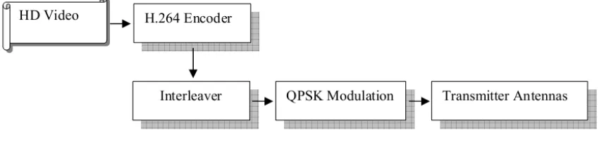
3.1 Transmitter Module
The HD video is processed and transmitted through the channel in this module. For encoding of the video, we make use of H.264 encoder. The encoded video is subsequently done interleaving
operation and QPSK modulation before the final transmission through antenna to the channel. The block diagram of the transmitter module is given in figure 2.
[image:4.612.95.520.577.678.2]ISSN: 1992-8645 www.jatit.org E-ISSN: 1817-3195 a.H.264 Encoder
The input HD video is initially encoded with H.264 encoder. H.264 is a video coding standard which plans for high presentation and discovers applications in broadcasting, storage onoptical, magnetic tool and DVD, conversational services over ISDN, Ethernet, LAN, DSL, wireless and mobile networks, modems. It is moreoverapplied in
video-on-demand and multimedia messaging
services (MMS).
The H.264 encoding procedure is carried out in two layers namely Video Coding Layer (VCL) and Network Abstraction Layer (NAL). In VCL, the video content is proficiently represented and in NCL, VCL representation is formatted and it givesthe header information. Here, H.264 encoding is maintained for video coding in either progressive
or interlaced frames, which may be mixed together in the same sequence.
Network abstraction layer
NAL arranges the information and provides the header information in a suitable way satisfactory for the transport layers or storage media. The entireinformationisenfolded in NAL modules, where every module contains an integer number of bytes. The NAL module utters a normal format to be used in packet-oriented and bit stream systems.
Video coding layer
H.264 video coding layer comprises of a combination of temporal and spatial prediction, in union with transform coding. Figure 3 gives the block diagramof the video coding layer.
Figure 3: Video Coding Layer
Thepictureis separated into permanent sized macro-blocks primarily. The primary picture in concern is generally intracoded which denotes that it does not employ any information apart from what is enfolded inside the picture. In this case, each sample is predicted using spatially neighboring samples of beforehand coded blocks. Inter coding is appliedusually for other pictures. Forecast based on formerly decoded pictures is executed in the inter coding. Now, at first the motion data comprising the reference picture is chosen and next, a spatial
dislocation is executed to all models of the block. The motion information is broadcasted as side information and presents the inter prediction signal.
The difference between the original and the
predicted block is calculated (d) and is
subsequently transformed (D). Here let the number
of blocks be equal to
N
. Transformation is carriedISSN: 1992-8645 www.jatit.org E-ISSN: 1817-3195 1 ,..., 0 , ) ) 2 1 ( cos( . 1 0 − = + =
∑
− = N b where b n N d D N n n b π ) 1 (Scaling and quantization operations are done for the transformed coefficients. For quantization, scalar quantization is used. Consequently, the coefficients are done entropy coding and are transmitted alongside with the side information which may be either intra-frame or inter-frame prediction. Here, decoder is contained in the encoder to perform prediction for the subsequent blocks or the next picture. As a result, the quantized transform coefficients are inverse scaled and inverse transformed as in the same procedure in the decoder side, giving the decoded prediction difference. This difference obtained is summed up with the prediction and the sum is given to the de-blocking filter which provides the decoded video as its output.
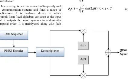
b.Interleaver
Interleaving is a commonmethodfrequentlyused in communication systems and finds a range of applications. It is hardware device in which symbols form fixed alphabets are taken as the input and it outputs the same symbols in a dissimilar temporal order. It is mainlyused along with fault
correction block codes to widen errors over a number of blocks so that the extreme number of faults in every block is below the number of correctable faults.
C.QPSK Modulation
Quadriphase Shift Keying (QPSK) modulation is a type of bandwidth preserving modulation method. Here, the information carried by the transmitted signal is contained in the phase. Transmitted signal is defined (equation 2) as:
<
<
−
+
=
else
T
t
i
ft
T
t
r
i,
0
0
,
4
)
1
2
(
2
cos
2
)
(
π
π
ε
) 2 (Two orthonormal basis functions are defined by (equations 3 & 4):
T
t
ft
T
t
)
=
2
cos(
2
),
0
<
<
(
1π
φ
) 3 (T
t
ft
T
[image:6.612.97.520.346.606.2]t
)
=
2
sin(
2
),
0
<
<
(
2π
φ
) 4 (Figure 4: QPSK Transmitter
Figure 4 gives the QPSK transmitter block diagram. Here the incoming sequence is first transformed into polar form with the use of Polar Non-Return to Zero (PNRZ) encoder. This is divided into waves consisting of odd and even numbered bits by means of a Demultiplexer. The waves are then multiplied with the respective
orthonormal signal functions of
φ
1(
t
)
andφ
2(
t
)
. The resultant waves are then summed up to have the final QPSK modulated signal.ISSN: 1992-8645 www.jatit.org E-ISSN: 1817-3195 3.2 Receiver Module In the receiver module, the received signal is
[image:7.612.88.527.72.331.2]demodulated, de-interleaved and decoded to have the output.The block diagram is given in figure 5:
Figure 5: Receiver Module
a.UWB channel
UWB stands for Ultra Wide band and has
obtained its name as it employs
remarkablyextensive transmission bandwidths
surplus of 3 GHz. UWB has the capacity for exact position location and ranging, absence of substantial fading, great multiple access capability, protected communications, and feasibleundisturbed material penetration. These all supply to having covered and more rapidly wireless networks. For
wireless positioning and ranging products, it moreoverassists in building enhanced plans. The channel formulates use of nanosecond impulses which offers the bandwidth in the range of 3-7 gigahertz. UWB moreover has the benefit of containing low power transmission model which allowsthe system to labour over a large bandwidth without meddling with prevailing narrowband systems.
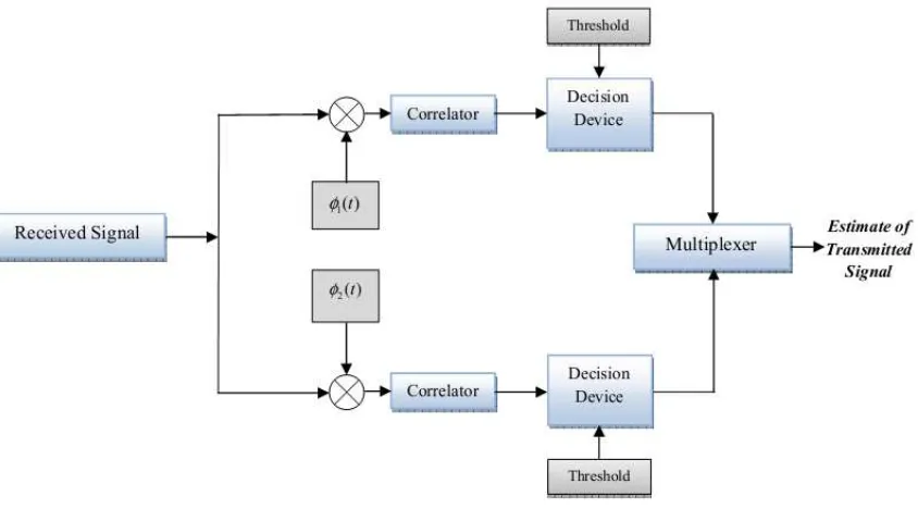
b.QPSK Demodulator
[image:7.612.100.522.481.715.2]ISSN: 1992-8645 www.jatit.org E-ISSN: 1817-3195
QPSK demodulator consist of correlators with a common input and supplied with reference
orthonormal signals of
φ
1(
t
)
andφ
2(
t
)
. The blockdiagram of the QPSK demodulator/ receiver is shown in figure 6. The received signals are multiplied with the orthonormal functions and are fed to the respective correlators. The correlator output signals are compared with the threshold set and the respective decisions are taken based on the
conditions. Finally the two are combined in a multiplexer to produce the estimate of the original signal.
C. De-Interleaver and decoder
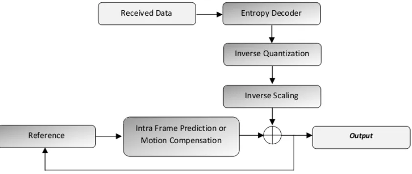
[image:8.612.98.519.227.405.2]In the receiver section, interleaved data is settled back into the original sequence by the use of de-interleaver.Subsequently, the decoding is carried and H.264 decoder which is shown in figure 7.
Figure 7: H.264 Decoder
After the de-interleaving, the data is fed to the H.264 decoder whereinitially entropy decoding is carried out. After decoding, it is inverse quantized and inverse scaled which is subtracted from the intra frame prediction or motion compensation (in case of inter frame) to result in the difference image. The prediction is carried out with comparison to the reference signal which is the feedback from the output signal. The output will be HD video and also parameters like PSNR and MSE values.
3.3 Rate Control Module
Usage of wireless internet video services is on a rapid rise and finds applications in major areas. But normal voice and data services differ from video applications in the fact that videos requires larger bandwidth and better quality of service with respect to the parameters like delay, fading, interference,
ISSN: 1992-8645 www.jatit.org E-ISSN: 1817-3195
Figure 8: Control Module
Peak Signal to Noise Ratio (PSNR) and Minimum Squared Error (MSE) of the output are found out and are given as the input to the fuzzy logic. The fuzzy logic in return produces the output values for rate of transmission and number of frames per transmission which will be given to the H.264 encoder in the transmitter module.
The visual quality of the received HD video computed the peak signal-to-noise ratio (PSNR). It is defined as the ratio of the maximum possible power of video signal to the power of corrupting noise and is normally given in logarithmic decibel scale.Mean squared error (MSE) can be defined as the difference between estimated values and the original value. It computes the average of the squares of all errors. MSE (equation 5) and PSNR (equation 5) can be defined as:
∑
=
−
=
ki
i
X
iX
k
MSE
1ˆ
1
) 5 ()
(
log
10
)
(
log
20
10I
max 10MSE
PSNR
=
−
(6)
Where,
Xˆ
is the vector ofk
predictions,Xˆ
isthe vector of true values,
I
max is the maximumpossible pixel value. The MSE and PSNR are given to the fuzzy module as the input.
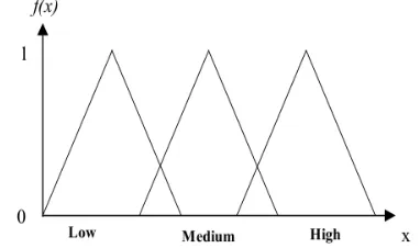
Fuzzy logic converts and processes the crisp values to fuzzy categorical values. In our case, we make use of triangular membership function, in which the input data values are three fuzzy values. Let the values be represented by low, medium and high represented by i, j and k. These form the three vertices of the triangular member ship function
defined by
f
(x
)
. The triangular membership isdefined by the formula (equation 7):
≥
≤
≤
−
−
≤
≤
−
−
≤
=
k
x
if
k
x
j
if
j
k
x
k
j
x
i
if
i
j
i
x
i
x
if
x
f
,
0
,
,
,
0
)
(
) 7 (Figure 9 shows the plot for triangular membership function. The three curves are for low, medium and high.
Figure 9: Plot Showing Triangular Membership Function
[image:9.612.330.489.342.436.2] [image:9.612.327.518.506.619.2]ISSN: 1992-8645 www.jatit.org E-ISSN: 1817-3195
• If PSNR is LOW and MSE is HIGH, THEN
transmission rate is HIGH and number of frames per transmission is LOW.
• If PSNR is MEDIUM and MSE is MEDIUM,
THEN transmission rate is MEDIUM and number of frames per transmission is MEDIUM.
• If PSNR is HIGH and MSE isLOW, THEN
transmission rate is LOW and number of frames per transmission is HIGH.
The obtained transmission rate and the number of frames per transmission is given into the H.264 encoder in the transmitter module.
4. RESULTS AND DISCUSSIONS
In this section, we discuss the results obtained for our proposed technique. In section 4.1, details about the HD videos used for experimentation is given and the evaluation metric employed are discussed. In section 4.2, comparative analysis is made where
our proposed results are compared with
SamiaShimuet al.[1] results.
4.1 Implemetation And Evaluation Metric
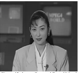
[image:10.612.335.515.75.240.2]Proposed transmission control technique for wireless video transmission is implemented using Matlab on a system having i-7 Pentium processor having 3 Giga Hertz and 4 Gigabytes of RAM. The technique is tested on three videos namely: Foreman video, Hall video and Akiyo video. Image sample from all the three videos are given below:
[image:10.612.340.496.253.399.2]Figure 10: Image Captured From Video 1
Figure 11: Image Captured From Video 2
Figure 12: Image Captured From Video 3
Assessment metric used is BER (Bit Error Rate) and MSE. The Bit Error occurs when the
received bits of the data stream over
a communication channel varies from the
transmitted signals. This occurs owing to modification of the signal which may happen due to the interference of not needed signals, noise
effects, distortions or bit synchronization errors,
multipath fading, attenuation. The bit error
rate or bit error ratio (BER) is the ratio of bit errors to the total transferred bits during the particular time interval. BER is presentation measure applied for calculating the concert or the functionality of different methods and systems.
4.2 Comparative Analysis
We compare our proposed method to the SamiaShimuet al.[1](existing paper) with the help
of evaluation metrics. We plot
BER
vs.o b
N
E graphs from which we can infer the
performance of the system.
o b
N
E is the energy per
bit
(
E
b) to noise power spectral density(
N
o)
ratioof the received signal. b
N
[image:10.612.116.274.464.601.2]ISSN: 1992-8645 www.jatit.org E-ISSN: 1817-3195 normalized signal-to-noise ratio (SNR) measure of
the signal.
BER
vs.o b
N
E plots are made for all
three videos and are given in figure 13, 14 and 15.
0 2 4 6 8 10 12 14 10-6
10-5 10-4 10-3
10-2 10-1 100
Eb/No
B
E
R
Video 1
[image:11.612.335.495.131.260.2]existing proposed
Figure 13: BER With Respect To Eb/No For Video 1for Our Proposed And For Samiashimu Et Al.[1]
0 2 4 6 8 10 12 14
10-5 10-4 10-3 10-2 10-1 100
Eb/No
B
E
R
Video 2
existing proposed
Figure 14: BER with respect to Eb/No for video 2 for our proposed and for SamiaShimu et al.[1]
0 2 4 6 8 10 12 14
10-6 10-5 10-4 10-3 10-2 10-1 100
Eb/No
B
E
R
Video 3
existing proposed
Figure 15: BER With Respect To Eb/No For Video 3 For Our Proposed And Samiashimu Et Al.[1]
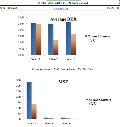
From figures 13, 14 and 15, we can observe that our proposed technique has got lower curve indicating lower BER and high performance of the system. The average values of BER are computed for each video and are given in table 1 and figure 16. MSE is also taken for each video and is given in table 1 and plotted in figure 17.
Table 1: Average BER And MSE Values Obtained For The Videos
BER MSE
SamiaShimu et al.[1]
Proposed SamiaShimu et al.[1]
Proposed
Video 1
0.0341 0.0340 330.5679 134.7181
Video 2
0.0340 0.0314 10.4122 6.4678
Video 3
[image:11.612.120.271.318.430.2]ISSN: 1992-8645 www.jatit.org E-ISSN: 1817-3195
0.029 0.03 0.031 0.032 0.033 0.034 0.035
Video 1 Video 2 Video 3
Average BER
[image:12.612.93.497.54.482.2]Samia Shimu et
al.[1]
Figure 16: Average BER Values Obtained For The Videos
0 50 100 150 200 250 300 350
Video 1 Video 2 Video 3
MSE
Samia Shimu et
al.[1]
Figure 17: MSE Values Obtained For The Videos
From the table 1 and figures 16-17, we can infer that our proposed technique has performed well by achieving lower BER and MSE compared with SamiaShimu et al.[1]. We can see that the net average BER for all three videos came about 0.034 for SamiaShimuet al. [1] compared to 0.032 for our proposed technique. Similarly, net average MSE for all three videos came 117 for the SamiaShimu et al. [1] compared to 48.8 for our proposedtechnique. These values indicate the lowering of errors and higher reception of the signal with better clarity and fidelity.
5. CONCLUSION
In this paper, we present transmission control technique for wireless video transmission over UWB channel using fuzzy logic and H.264 encoder. Transmission module, control module and
[image:12.612.149.350.316.478.2]ISSN: 1992-8645 www.jatit.org E-ISSN: 1817-3195 show the efficiency of the proposed technique by
having lower MSE and BER values.
REFERENCES
[1] SamiaShimu, Khan A. Wahid and AnhDinh, “Wireless transmission of HD video using H.264 compression over UWB channel”, Journal of Real-Time Image Processing Vol. 7, No. 4, pp 233-246, 2012.
[2] unXu, Xuemin (Sherman) Shen, Jon W. Mark and Jun Cai, " Adaptive Transmission of Multi-Layered Video overWireless Fading Channels ", IEEE transactions on wireless communications, vol. 6, no. 6, june 2007.
[3] M. Padmaja, P. Satyanarayana, K. Prasuna and
G.Naveen Kumar, "Wireless Image
Transmission Using Maximum Power
Adaptation Algorithm", International Journal of Engineering Research and Development, vol. 4, no. 8, p p.57-63, 2012.
[4] Xiaoan Lu, Yao Wang, and ElzaErkip, "Power efficient h.263 video transmission over wireless channels", IEEE journal on selected areas in communications, vol. 21, no. 10, december 2003.
[5] Vıctor Miguel, Juli´an Cabrera, Fernando Jaureguizar and Narciso Garcıa, "A wireless video transmission control approach through
stochastic dynamic programming", Image
Processing (ICIP), p p.4457-4460, 2010. [6] Leonardo Badia, Nicola Baldo, Marco Levorato
and Michele Zorzi, "A Markov Framework for Error Control Techniques Based on Selective Retransmission in Video Transmission over Wireless Channels", IEEE journal on selected areas in communications, vol. 28, no. 3, april 2010.
[7] Reuben A. Farrugia and Carl James Debono,"Digital Video Transmission over Wireless Channels using Pixel-Level Artefact Detection Mechanisms", International Journal of Engineering Research and Development, vol.3, p p. 573-612,2010.
[8] Laura Galluccio, GiacomoMorabito and
Giovanni Schembra, "Transmission of Adaptive MPEG Video OverTime-Varying Wireless
Channels: Modeling and Performance
Evaluation", IEEE transactions on wireless communications, vol. 4, no. 6, november 2005.
[9] A. Cernuto, F. Cocimano, A. Lombardo, and G. Schembra, “A queueingsystem model for the design of feedback laws in rate-controlled MPEG video encoders,” IEEE Transforming Circuits System Video Technology, vol. 12, no. 4,pp. 238–255, Apr. 2002.
[10] A. Lombardo, G. Morabito, and G. Schembra, “An accurate and treatable Markov model of
MPEG-video traffic,” IEEE Information
Communications , p p. 217–224, March 1998. [11] A. Lombardo and G. Schembra, “Performance
evaluation of an adaptive- rate MPEG encoder
matching traffic constraints,” IEEE
Transforming Network, vol. 11, no. 1, p p. 47– 65, Feb 2003.
[12] A. Panayides, M. S. Pattichis, S. Pattichis,C. P. Loizou, M. Pantziaris, and Andreas Pitsillides, "
Atherosclerotic Plaque Ultrasound Video
Encoding, Wireless Transmission, and Quality Assessment Using H.264",IEEE transactions on information technology in biomedicine, vol. 15, no. 3, may 2011.
[13] Fangwen Fu and Mihaela van der Schaar, "A
Systematic Framework for Dynamically
Optimizing Multi-User Wireless Video
Transmission", IEEE journal on selected areas in communications, vol. 28, no. 3, april 2010. [14] EhsanMaani, Peshala V. Pahalawatta, Randall
Berry and Aggelos K. Katsaggelos, "Scalable Video Coding and Packet Scheduling for Multiuser Video Transmission Over Wireless Networks", IEEE Transcations and information, vol.89, no.1, p p.6-20, 2001.
![Figure 14: BER with respect to Eb/No for video 2 for our proposed and for SamiaShimu et al.[1]](https://thumb-us.123doks.com/thumbv2/123dok_us/8913735.960654/11.612.335.495.131.260/figure-ber-respect-eb-video-proposed-samiashimu-et.webp)