Design of Active Electromagnetic Interference Filter to
Eliminate Common-mode Noise in Conducted
Interference
P.V.Y.Jayasree
Department of Electronics and Communication Engineering
GITAM University Visakhapatnam, AP
G.Raghu Poojita
Department of Electronics and Communication Engineering
GITAM University Visakhapatnam, AP
J.Chaitanya Priya
Department of Electronics and Communication Engineering
GITAM University Visakhapatnam, AP
ABSTRACT
Passive Electromagnetic Interference (EMI) filters are being replaced with active EMI filters these days for dealing with high-frequency noise interference. Based on the measured values of noise source and noise termination impedances of equipment under test, a practical example of the design of an EMI filter to comply with the regulatory limits of conducted EMI is demonstrated. The elimination of Common-mode (CM) noise considering the design of both passive and active EMI filters is exhibited in the frequency range of 150 KHz-1MHz and although both of these filters allow the SMPS to pass the EMI limits, designing active EMI filters leads to optimal component values and eliminates CM noise over a wider frequency range.
General Terms
Active electromagnetic interference filter, common-mode noise, conducted interference, electromagnetic interference, insertion loss, passive electromagnetic interference filter.
Keywords
Active EMI filter, CM noise, conducted interference.
1.
INTRODUCTION
Electromagnetic Interference (EMI) filters are used in electronic equipment to enable them to comply with the EMI specification limits [1]. Passive EMI filters are bulky, heavy and exhibit a poor compensation and are not very efficient in eliminating high frequency noise components. A new class of power line filters overcoming these limitations is ceramic filters, lossy line filters and active filters [2]. Several systematic analyses of EMI filters have appeared recently that have evaluated an active EMI filter for CM noise reduction [3-5]. Filter performance characteristics depend on several parameters: insertion loss, input and output impedances, cut-off frequency etc [2]. The insertion loss as a function of frequency is the most fundamental characteristic of a filter defined as,
(1)
where, 1 is the output voltage of signal source without filter
in setup and 2 is the output at filter terminals with the filter
in the setup. For filter designs in the conducted emissions range that is typically from 150 KHz-3MHz, the filters are designed to satisfy the EMI regulatory limits. Table1 shows the CISPR 22 EMI regulatory conducted emission limits. For filter designs of microwave applications, the source and noise impedances are generally specified to be 50Ω. Some EMI
filter design methods do not consider these impedances but few methods do take into account these values to avoid overdesign [6].
Table 1. Conducted Emission limits for Class A and Class B devices
CISPR 22 Conducted Emissions Limits for Class A Devices Frequency (MHz) µV QP (AV) dB(µV) QP
(AV)
0.15 - 0.5 8912.5 (1995) 79 (66)
0.5 - 30 4467 (1000) 73 (60)
CISPR 22 Conducted Emissions Limits for Class B Devices
Frequency (MHz) µV QP (AV) dB(µV) QP (AV)
0.15 - 0.5 1995-631 (631-199.5)
66-56 (56-46) (limit varies linearly)
0.5 - 5 631 (199.5) 56 (46)
5 - 30 1000 (316) 60 (50)
In this paper, based on measurements performed in AWR-Microwave Office using circuit schematics of conducted emission setup, suitable passive EMI filters are designed for the EUT and the results are validated through simulations in MATLAB. With these obtained results, the limitations of using LC inductor or choke filter are discussed and a simple active EMI filter design has been proposed to overcome these limitations [7]. The active filters are small, compact and the CM interference levels and insertion losses after including these filters are demonstrated and the results are compared to exhibit the effectiveness of using active EMI filters at microwave frequencies.
2.
MEASUREMENT PROCEDURE
2.1
Impedance measurements
Precise information of the CM noise source and noise termination impedances over the desired frequency of interest is necessary to decide on an appropriate EMI filter configuration to meet a specific conducted EMI limit and to maximize filter performance [5]. In this paper, this measurement is done through circuit schematics by following the below procedure.
2.1.1
CM noise termination impedance
The input from the ac power supply is fed to the EUT (SMPS acting as the noise source) through LISN that acts as the termination impedance for CM noise source. To measure this CM noise termination impedance, a 1-µF capacitor is connected between the line and ground nodes and another 1-µF capacitor is connected between the neutral and ground nodes of the LISN [6] and the SMPS is removed. For commercial purposes, this LISN impedance is usually around 50Ω over the conducted emissions frequency range.
2.1.2
CM noise source impedance
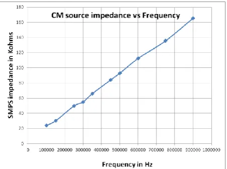
[image:2.595.315.575.75.175.2]The impedance of the noise source, which is the EUT can be measured by connecting a CM inductor (28mH) in series with the source/load and removing the LISN. The values obtained for the CM source impedance across 150 KHz-1MHz is shown in Figure1. The impedance increases almost linearly with frequency until 1MHz and remains constant above that.
Figure 1. Common-mode noise source impedance curve
2.2
CM noise measurement
Once the noise impedances are measured, the CM noise measurement setup is connected as in Figure2. The EUT is powered by 220V ac power supply that is fed through the LISN and the CM noise produced due to the switching elements in the EUT are tapped at the ‘line’ and ‘neutral’ terminals of the LISN and measured across the output of the CM noise separator [8]. This noise separator rejects the differential-mode form of conducted emissions and gives only the common-mode noise as output. This output is given by,
D2 D1N4002
R7 0.05k C4
0.1uF C2
1uF
R15 10k
2.2e-3H
C3
0.1uF
R6
0.016k
D1 D1N750
R17 2.2k R1847k C1
1uF
R16 47k Q1 Q2N2222
R1
0.05k L250uH
R9
0.016k
R3
0.05k R2
1k
C7 1e-9F L4
28mH
R5
0.05k V1
220Vac 0Vdc
R14 47k L1
50uH
R4 1k
R8
0.016k
C8 100e-6F
[image:2.595.316.542.258.421.2]Q2 Q2N2222
Figure 2. Common-mode noise measurement schematic in
AWR-Microwave Office
These noise levels when compared with the CISPR 22 EMI specified standards (as in Table1), are found to exceed them and this has been shown in Figure4.
Figure 4. CM noise voltage exceeding EMI limit when
filter is not used
The EMI filter is required to reduce these emissions and make the EUT comply with the EMI limits. The amount by which the CM noise is above the EMI limit is the minimum required insertion loss required for the design of the filter. Hence, the filter should satisfy the below condition in order to comply with the EMI limits:
(3)
where, is the designed insertion loss and is the obtained CM noise voltage without using filter and is the CISPR 22 EMI regulatory limit for conducted emissions.
2.3
EMI Filter design process
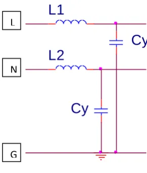
[image:2.595.55.281.359.527.2]L2
Cy
[image:3.595.315.543.70.242.2]Cy
L1
Figure 5. LC inductor filter
To increase the attenuation and to realize a steep skirt response, several LC stages may be cascaded. Capacitors Cy
bypass the CM current to ground. When the source and load impedances are unequal, the largest insertion loss will usually be achieved when the capacitor shunts the higher impedance (load or source) [9]. The filter is placed between the LISN and EUT and the filter is composed of two CM inductors (L1 and
L2) and two CM capacitors (each Cy). The total capacitance,
Ct is,
(4) The value of CM capacitance is usually constrained by safety requirements and hence, the maximum capacitance connected to ground should not exceed about 4700pF on each phase for 250Vac 50Hz power supply [10].
(5)
So, each capacitance of 1pF is chosen for the design and hence,
(6) Using these known capacitances, the CM inductors are tuned to the required value such that they could provide the CM filter insertion loss indicated in equation2. The tuned values of CM inductors are,
(7) With these inductances the obtained CM noise was in accordance with the levels mentioned in Table1. The results obtained are shown in Figure6.
Figure 6. CM noise voltage with and without LC inductor
filter
The cut-off frequency of this filter is given by,
where, is the resonant frequency of the filter, L, C are the designed inductance and capacitances of the filter. At high frequencies, this filter gives poor attenuation and the resonance effects caused by lead inductance of the capacitors are of critical importance.
2.3.2
Choke filter
For the LC inductor filter, the desired results were confined only from 250 KHz-1.05MHz. Hence, a CM choke inductance was employed instead of two inductors. The most important design consideration in power line filter designs is the method of winding CM inductor choke [2].
The winding should be done with minimum interwinding capacitances and the CM chokes perform well because the permeability to common-mode currents is much larger [11, 12]. The circuit is similar to that shown in Figure5 but, a single choke inductance is used here. The CM capacitances were 1pF each and the tuned CM choke inductance was about 2mH that produced almost negligible CM noise across the output of noise separator.
(9) But, choke filters have a poor compensation and they too operate well only over a narrow range of frequencies due to parasitic affect of the passive components and the limitations of the leakage inductance. Several published papers [11, 13-16] have investigated and analyzed CM currents. Keeping in view all these drawbacks of passive EMI filters, the design of a simple active EMI filter was considered a good alternative and the schematic employing an active EMI filter is shown in Figure7.
L
N
[image:3.595.80.226.75.246.2]R14 47k
C4 0.1uF
2.2e-3H
R5
0.05k
Q1 Q2N2222 L1
50uH L4
28mH
R7
0.05k
V3
1Vdc
C6 1pF
R15 10k
R1
0.05k C2 1uF
C8 100e-6F
C5
1pF V2
1Vdc
R16 47k
U3A
LM324
1 3
2
4
11
OUT +
-V+
V-R4 1k
T3coupled
in2 out1 in1
out2 out3 in3
R9
0.016k
R18 47k R10
0.5k
C7 1e-9F L2
50uH
R2
1k R3
0.05k
R12
1M
Q2 Q2N2222
R8
0.016k V1
220Vac
0Vdc
R6 0.016k
R11
1k R13
1k C3
0.1uF
C1
1uF R17
2.2k
D2 D1N4002 D1
[image:4.595.57.520.81.311.2]D1N750
Figure 7. Active EMI filter schematic connected in PSPICE
2.3.3
Active EMI filter
The active EMI filter consists of a 741 op-amp along with some resistors and capacitors. A coupled transformer was used between the LISN and the EUT and the high-voltage capacitors C1 and C2 should not be too large to meet the
leakage current safety specifications. Hence, the capacitances chosen were,
(10) The Coupled transformer was tuned to specific values such that it produced reduced CM noise satisfying the condition in equation2. The designed internal parameter values of the CM coupled transformer are,
(11) With these component values, the active EMI filter produced desired results over a wider range of frequencies until about 3MHz unlike the passive EMI filters designed previously and this reduced CM noise using active EMI filter is shown in Figure8.
3.
RESULTS AND COMPARISONS
The comparison of CM noise voltages obtained by employing LC inductor and choke filter as can be seen in Figure8, are below the specified CISPR conducted emission EMI limit. By employing a LC inductor filter, desired results are obtained only from about 250 KHz and for frequencies lower than 250 KHz, larger passive component (Zseries or Zshunt) is needed to
acquire required insertion loss. So, the noise impedance
Figure 8. CM noise voltage comparisons using passive and active EMI filters
[image:4.595.315.544.341.528.2]Figure 9. CM noise voltage of active EMI filter across a wide frequency range
Figure 10. Insertion loss curves
The insertion losses for both the designed passive and active EMI filters were simulated in MATLAB and the graph showing these comparisons is visible in Figure 10.
Table 2. Comparison of results between passive and active EMI filters
Measurement in
150KHz-1.05MHz
LC inductor
filter
Choke filter
Active EMI filter
Maximum Common-mode noise
-60.3dB -294.6dB -174dB
Maximum Insertion loss
90dBµV 310dBµV 200dBµV
Frequency range in which desired output
is obtained
250KHz-1.05MHz
150KHz-1.05MHz
150KHz-3MHz
From this figure, it can be clearly observed that for frequencies below 250 KHz, the LC inductor filter is not satisfying the condition in equation1. The comparison of results between the passive and active EMI filter is tabulated in Table2.
4.
CONCLUSIONS
The measured and simulated results in this measurement process show that over a narrow frequency range of 150KHz – 1MHz, the passive EMI filters could be used to reduce the common-mode noise levels below the regulatory limits but as the frequency increases beyond 1MHz, the affect of parasitic components on the measured values increases and the passive EMI filters become bulky and heavy. On the other hand, the active EMI filters are compact, light and could be used over a wider range of frequencies and over the entire conducted emission range, from 150 KHz-3MHz producing reduced common-mode noise that is compliant with the CISPR 22 EMI limits. The use of active EMI filters are hence a better alternative to passive EMI filters for reducing the unwanted common-mode noise form of conducted interference.
5.
ACKNOWLEDGMENTS
We thank the management of GITAM University for all the support and encouragement rendered in this work. Our sincere thanks to the Principal of Gitam Institute of Technology, Head of the Department of E.C.E and its staff for their kind support. [1] REFERENCES Mohit Kumar, Vivek Agarwal,’Power line filter design for conducted electromagnetic interference using Time-Domain Measurements’, IEEE Transactions on Electromagnetic Compatibility, Vol.48, No.1. February 2006.
[2] V Kodali Prasad, ‘Engineering Electromagnetic Compatibility’, IEEE, Inc, New York.
[3] Wenjie Chen, Weiping Zhang, Xu Yang, Zhiyong Sheng, Zhaoan Wang, ‘An experimental study of common-and differential-mode active EMI filter compensation characteristics’, IEEE Transactions on Electromagnetic Compatibility,Vol.51, No.3, August 2009.
[4] N.K.Poon, J.C.P.Liu, C.K.Tse and M.H.Pong, ‘Techniques for input ripple current cancellation: Classification and implementation’,IEEE Trans.Power Electron.,Vol.15,No.6,pp 1144-1152,Nov 2000.
[5] Y.C.Son and S.K.Sul, ‘Generalization of active filters for EMI reduction and harmonics compensation’, IEEE Trans. Ind. Electron., Vol.42, No.2, pp. 545-551, March.2006.
[6] Vuttipon Tarateeraseth, Kye Yak See, Flavio G. Canavero, Richard Weng-Yew Chang,’Systematic Electromagnetic Interference Filter Design Based on Information From In-Circuit Impedance Measurements’, IEEE Transactions on Electromagnetic Compatibility,Vol.52, No.3, August 2010.
[7] Wenjie Chen, Xu Yang, Zhaoan Wang, ‘An active EMI Filtering Technique for Improving Passive Filter Low-Frequency Performance’, IEEE Transactions on Electromagnetic Compatibility, Vol.48, No.1, February 2006.
[image:5.595.61.290.530.763.2]Electromagnetic Compatibility, Vol.50,No.3,August 2008.
[9] J.J.Goedbloed, Electromagnetic Compatibility, Englewood Cliffs, NJ:Prentice-Hall, 1990.
[10]T.Williams, EMC for product designers, 4th ed. London, U.K,: Newnes,2007.
[11]Bin-Chyi Tseng, Lin-Kun Wu, ‘Design of Miniaturized Common-Mode Filter by Multilayer Low-Temperature Co-Fired Ceramic’, IEEE Transactions on Electromagnetic Compatibility, Vol. 46,No.4, November 2004.
[12]J.D.Gavenda,’Measured effectiveness of a toroid choke in radiating common-mode current’,in Proc.IEEE Int.Symp.Electromagnetic Compatibility, 1989.
[13]R.F.German, H.W.Ott, and C.R.Paul, ‘Effect of an image plane on printed circuit board radiation’,in Proc.IEEE Int.Symp.Electromagnetic Compatibility, 1990.
[14]C.R.Paul,’A comparison of the contributions of common-mode and differential-mode currents in radiated emissions’, IEEE Trans .Electromagnetic Compatibility, Vol.31,May1989.