Behavior based Automated Test Case Generation for
Object Oriented Systems
Rohin Verma
Department of Computer Science & Engineering, Thapar University
Patiala, Punjab, India
Rajesh Bhatia
Department of Computer Science & Engineering, Deenbandhu Chhotu Ram University of Science &
Technology
Murthal (Sonepat), Haryana, India
ABSTRACT
An innovative approach of generating test cases from the combination of UML design diagrams has been discussed in this paper. Present work used an approach where petal files of class diagram, sequence diagram and state chart diagram has been used to generate test cases. The test cases thus generated are suitable for static and dynamic testing of system.
General Terms
Test case generation from UML diagrams.
Keywords
Class diagram, Petal file, Sequence diagram, SQL *Loader, Statechart diagram, Test cases.
1.
INTRODUCTION
Software Testing is the process of executing a program with the intention of finding errors [1]. Every software code has been reviewed and verified through SQA activities but these activities are not sufficient. Every time the software delivered to the client has been thoroughly tested by client before sending it to the production. Thus developer has to test the software before it gets to the client.
Testing has been generally performed by three ways: white- box testing, black box testing and gray-box testing [2-3]. Day by day with increasing functionality of software has caused increasing complexity and size of software applications due to this reason more emphasis has been sited on object oriented design strategy to cut down software cost and boost software reusability. The Object oriented design strategy used designing and implementing software has created new challenges in testing. Object oriented features like polymorphism, abstraction, encapsulation and inheritance has created lot of challenges for tester while testing the software. Thus object-oriented software needs different tactics for testing software effectively during all phases of a development effort. The review of analysis and design models is the base for testing object oriented programs. Object oriented software has been tested by executing test cases for individual operation of a class and then by executing test cases to find the error when one class collaborates with other class. Software is made by integrating different subsystems and each subsystem is composed by integrating classes. Use based testing and fault based testing has been used to test these subsystems [4, 5]. The testing techniques discussed so far is good to test software what it was supposed to do but it will not test what is missing in software code. From last few years there has been slow development made to the testing of object-oriented systems. One innovative approach is to use UML models for test cases generation. This approach can lead to find out faults in the design phase prior to the development phase and thus causes correction of faults in early life cycle
stages of software. This type of testing comes under the category of gray-box testing. There are number of publications that have been emerging over the last few years [6-10], that are based on UML models. UML models are nothing but diagrammatical representation of specification document. UML diagrams can be used as a base to derive test cases and to develop testing environments. However, using UML diagrams to derive test case is not an easy task. A test case contains initial state, test sequence, constraints, final state and expected output, where constraints are the pre- and post condition for that input values. Collecting information like pre and post condition from UML diagram is a difficult task. The solution to this problem is to augment the design with the information like pre condition, post condition and providing inter class dependency through class diagram. However information like these will complicate the automated testing. Several researches have been done to automate test case generation from UML design and this paper also provides contribution to automate the test case generation from UML diagrams.
The rest of the paper is organized as follows. Related Work is discussed in section 2. Proposed Methodology is discussed in section 3. In present work a tool has been generated and in section 4 Experimental Setup for the tool has been discussed. In section 5 a case study has been taken to generate the test cases. Section 6 describes the test cases generated by the tool for the case study with screen shots. Section 7 cites the comparison of test cases generated in section 6 with the test cases generated from the approach used in different research papers [19][21] . Finally section 8 concludes this paper.
2.
RELATED WORK
Kirani and Tsai [14] suggested “inter class test case generation” approach. Class collaboration testing will be accomplished in similar way as testing of individual class occurs.
Some research has been reported to generate test cases based on interaction diagram. Sequence diagram along with collaboration diagram comes under modeling called Interaction modeling. Interaction diagram has been used to represent a combination of dynamic and structural modeling where dynamic modeling has been represented by sequence diagram as it gives emphasis on time ordering of messages and structural modeling has been represented by collaboration diagram as it emphasizes on structural organizations of objects those participate in messages communication. The name interaction as such reveals that this type of modeling concentrates on control flow through multiple interacting instances. For testing these two types of diagrams a control flow graph has been developed that contains multiple entities. Now the entire traditional graph based test coverage techniques can be applied to this control flow graph as outlined in [15]. This includes branch coverage, path coverage and round trip scenario coverage criteria [16]. Since UML diagrams are always more abstract and provides ease to generate test cases than control flow graphs so researchers have started using UML diagrams to generate automated test cases from UML diagrams. Philip Samuel, Rajib Mall and Sandeep Sahoo have presented a novel testing methodology to test object-oriented software based on UML sequence diagrams [17]. This paper has presented an approach to generate test cases automatically from UML sequence diagrams using dynamic slicing technique [17]. With the help of message guards and conditional predicates of sequence diagram dynamic slices have been created. Then these slices were used to generate test cases. A unique approach called slice coverage criterion has been used to validate the test cases. Dynamic slice approach accomplishes sufficient test coverage without excessively increasing the number of test cases. Li Bao-Lin, Li Zhi-shu, Li Qing and Chen Yan Hong have presented a new test cases generation approach that is based on UML sequence diagrams and Object Constraint Language/OCL [18]. The sequence diagram has been transformed to a tree representation. Firstly by selecting conditional predicates from sequence diagram whole constructed tree has been traversed. Then, pre and post conditions have been applied with the help of OCL. OCL alter the conditional predicates on sequence diagram and thus test cases have been generated by applying function minimization technique [18]. Message path coverage and constraint attribute coverage can be achieved from the test cases thus generated for all the objects which are related to the message [18]. Test cases generated by this approach covers class, operations, attributes, data limits and objects based test cases. Where class, attributes, operations based test cases have been generated from class diagram, data limit based test cases have been generated from OCL and objects from sequence diagram. Monalisa Sarma, Debasish Kundu, Rajib Mall have presented a novel approach of generating test cases from UML design diagrams [19]. In this research attempt, test cases have been derived from SDG (Sequence diagram graph). Firstly sequence diagram has been altered into a graph called Sequence diagram graph (SDG). SDG nodes have been augmented with different information from use case templates, class diagrams and data dictionary to compose test vectors [19]. Then SDG has been traversed to generate test cases. Test cases thus generated are helpful in detecting interaction faults, scenario faults and system testing can also be achieved.
State chart diagram and activity diagram are two diagrams through which UML supports behavioral modeling. Every object respond on the receipt of event and statechart diagram represent the behavior of an object by specifying how that object responds to the particular event. State based testing can be used to detect correct implementation of component’s state model. Test cases generated from state chart diagram concentrates on individual states of object and transitions between different states. P. Samuel R. Mall A.K. Bothra has developed a novel method to automatically generate test cases based on UML state models [20]. This research paper has presented an attempt to generate automated test cases from control flow and data flow logic present in UML state chart diagram. State machine has been traversed to generate test cases for every conditional predicates on every transaction. Test cases have been generated firstly by transforming conditional predicates and then by applying functional minimization technique [20]. The test cases generated satisfy transition path coverage criteria and can be used to test cluster-level state-dependent behaviors [20].
3.
PROPOSED METHODOLOGY
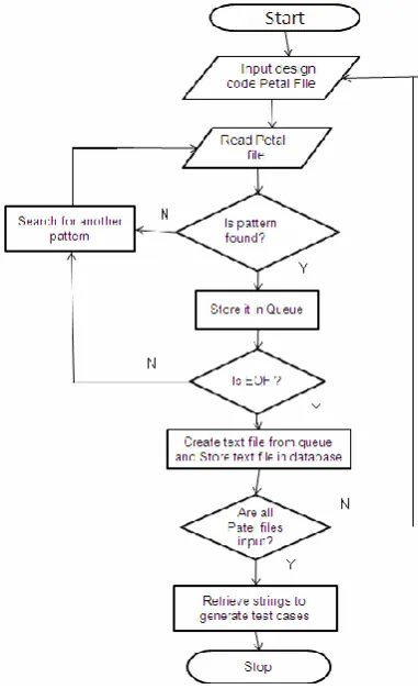
[image:3.595.319.510.106.420.2]Generally test cases have been generated from individual UML diagram, but the test cases generated by single diagram are not effective and efficient because test cases that have been generated depend on single view only. If combination of diagrams has been used then test cases generated will be more efficient and effective as they will cover both static and dynamic aspects of the system. Thus the proposed system focuses on the three UML diagrams for test cases generation: Class Diagram, Sequence Diagram and Statechart Diagram. Various types of information can be extracted from these diagrams to generate test cases. For static information class diagrams have been used and for dynamic type of information sequence and statechart diagrams have been used. Class diagram has been used to get the information related to Classes, Relationship between classes/Association, Dependency, Generalization/ Parent-child relationship, Operations, Cardinality, and Attribute. Sequence diagram has been used to get the information about Object interactions i.e. messages sent to other objects, Precondition for a particular message, Post-condition for a particular message. Statechart diagram has been used to get the information about Initial state of a system, Final state of a system, Guard conditions, Transitions. Combination of class, sequence and statechart diagrams i.e. all the required information from each diagram has been extracted to generate test cases for a particular system. The major steps of methodology have been given in Figure 1. Following are the major steps in prepared technique: 1) Input design Code Petal File: The Petal file of class diagram has been given as input to the developed tool. 2) Read petal file: Petal file has been read by the tool and string matching mechanism has been used to find a pattern like class name, class attributes, class cardinality, class operations, inheritance, dependency etc. 3) Is pattern found: If pattern has been found then it is entered to the queue else next pattern has been found. 4) Store it in a queue: All patterns found have been stored in a queue. There are different queues for every pattern like class name queue, class attributes queue, class cardinality queue, class operations queue, inheritance queue, dependency queue etc. 5) Search for another pattern: Tool searches for various patterns in petal file. For example if class name has been found then class name has been entered into the class name queue Else if class attributes has been found, then tool enters it to the class attributes queue similarly so on. 6) Is EOF (End of File): Tool keeps on searching the patterns until EOF? 7) Create text file from queue and store text file in database: When end of file has been reached, the tool generates the text file which contains all information about class diagram in form of tuples which can be entered to the database easily using SQL *Loader. SQL *Loader (Oracle load data files feature) loads all the data from the text file to the oracle database. 8) Are all Petal files input: After class diagram, Petal files of sequence diagram and statechart diagram have been entered to the tool. 9) Retrieving strings to generate test cases: Oracle database which contains the information from class diagram, sequence diagram, statechart diagram has been used to generate test cases. Tool has been
used to invoke queries that have been written in java to generate test cases.
Figure 1 Flow Chart for Methodology Used
4.
EXPERIMENTAL SETUP
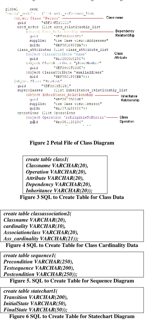
diagram Pre-conditions, Post-conditions and messages send to other objects have been searched by the tool, and from statechart diagram initial state, final state, guard conditions have been searched by the tool. Once searching has been over all the data in the form of text file has been generated by the tool. Text file of sequence diagram contains information in the form of tuples as Pre-condition, Post-conditions and messages. Similarly text file of statechart diagram contains information in the form of tuples as guard conditions, initial state, and final state. Now tables have been created in Oracle. The sql to create table for class data has been shown in Figure 3, and for class cardinality data is shown in Figure 4, Similarly SQL to create table for sequence diagram and statechart diagram has been shown in Figure 5 and Figure 6.
Figure 2 Petal File of Class Diagram
create table class1( Classname VARCHAR(20), Operation VARCHAR(20), Attribute VARCHAR(20), Dependency VARCHAR(20), Inheritance VARCHAR(20));
Figure 3 SQL to Create Table for Class Data
create table classassociation2( Classname VARCHAR(20), cardinality VARCHAR(10), Associationclass VARCHAR(20), Ass_cardinality VARCHAR(21));
Figure 4 SQL to Create Table for Class Cardinality Data
create table sequence1( Precondition VARCHAR(250), Testsequence VARCHAR(200), Postcondition VARCHAR(250));
Figure 5. SQL to Create Table for Sequence Diagram
create table statechart1( Transition VARCHAR(200), InitialState VARCHAR(50), FinalState VARCHAR(50));
Figure 6 SQL to Create Table for Statechart Diagram
Data from text file has been entered to the tool with the help of SQL *Loader [23]. In order to enter the data from text file
to Oracle database Dat and control files have been created. Dat file is nothing but text file generated from tool with the extension of .dat and control file is a text file written in a language that SQL*Loader understands. The control file tells SQL*Loader where to find the data, how to parse and interpret the data, and where to insert the data. Figure 7 shows the syntax of control file.
LOAD DATA
INFILE 'C:\Documents and
Settings\Rohin\Desktop\classresult.dat' APPEND INTO TABLE class1 FIELDS TERMINATED BY","
(Classname,Operation,Attribute,Dependency,Inheritance)
Figure 7 Control file syntax used in Oracle
All the data from class diagram, sequence diagram, Statechart diagram has been entered to the Oracle database using dat files and control files. With the help of JDBC java has been connected to Oracle database and queries have been invoked from java on different tables to extract the data and to generate the test cases.
5.
RESULT AND DISCUSSION
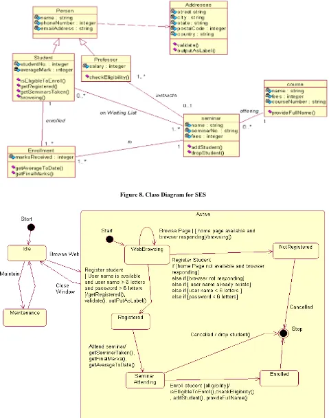
The tool developed has been tested with the help of a case study of Student Enrollment System (SES). The class diagram for SES has been shown in Figure 8. This represents the static view of the system now each operation, attribute, association in class can be used to derive test cases.
Figure 8. Class Diagram for SES
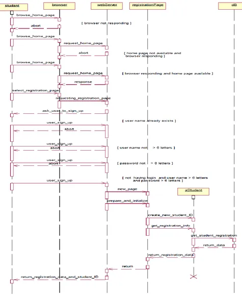
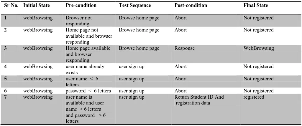
Table 1. Test Cases Generated from Statechart & Sequence Diagram for Operation getRegistered()
Sr No. Initial State Pre-condition Test Sequence Post-condition Final State
1 webBrowsing Browser not responding
Browse home page Abort Not registered
2 webBrowsing Home page not available and browser responding
Browse home page Abort Not registered
3 webBrowsing Home page available and browser responding
Browse home page Response WebBrowsing
4 webBrowsing user name already exists
user sign up Abort Not registered
5 webBrowsing user name < 6 letters
user sign up Abort Not registered
6 webBrowsing password < 6 letters user sign up Abort Not registered 7 webBrowsing user name is
available and user name > 6 letters and password > 6 letters
user sign up Return Student ID And registration data
registered
[image:7.595.310.561.467.765.2]Now class diagram has been combined to generate more effective test cases. Every class diagram has uses (dependency), inheritance and association relationships. These relationships have been used now to generate test cases. As shown in Figure 8, a class person depends on a class addresses so any test case derived for class addresses has been also used in class person for testing. Similarly class student and class professor has inheritance relationship with class person, so all test cases derived for operations of class person has been used as such in all child classes for testing child classes, also if there is any other method in child class or there exists any method in parent class that has been overridden in child class then it is needed to derive test cases for that method too.
Table 2. Database of Sequence Diagram
Precondition Test Sequence Post condition
Browser not responding
“browse_home_page” Abort
Home page not available and browser responding
“browse_home_page” Abort
Home page available and browser responding
“browse_home_page” Response
User name already exists
“User_sign_up” Abort
User name < 6 letters
“User_sign_up” Abort
Password < 6 letters
“User_sign_up” Abort
User name is available and user name > 6 letters and password > 6 letters
“User_sign_up” Student ID and registration data
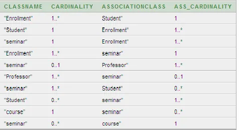
[image:7.595.49.287.480.733.2]The data extracted from class diagram has been shown in Table 4 and Table 5. There are two tables for class diagram first one (Table 4) contains information about Classname, Operation, Attribute, Dependency, and Inheritance and second (Table 5) contains the information of cardinalities of class and associated class. The table for association contains columns Classname, Cardinality, Associationclass and Ass_cardinality. With the help of Table 4, the information about the inheritance relationship between classes can be extracted. It can be found which is parent and which is child as shown in Table 4 person class is parent of student and professor. Thus any method that has been overridden in child can be found.
Table 3. Database of Statechart Diagram
Transition Initial State Final State
User name is available and user name > 6 letters and password > 6 letters
“WebBrowsing” “:Active:Registered ”
getRegistered “WebBrowsing” “:Active:Registered ”
Validate “WebBrowsing” “:Active:Registered ”
outPutAsLabel “WebBrowsing” “:Active:Registered ”
Home page available and browser responding
“WebBrowsing” “:Active:WebBrows ing”
Browsing “WebBrowsing” “:Active:WebBrows ing”
Home page not available and browser responding
“WebBrowsing” “:Active:NotRegiste red”
Browser not responding
“WebBrowsing” “:Active:NotRegiste red”
User name already exists
“WebBrowsing” “:Active:NotRegiste red”
User name < 6 letters
Password < 6 letters
“WebBrowsing” “:Active:NotRegiste red”
getSeminarTaken “Registered” “:Active:SeminarAt tending”
getFinalMarks “Registered” “:Active:SeminarAt tending”
getAverageToDate “Registered” “:Active:SeminarAt tending”
Elligibility “SeminarAttending” “:Active:Enrolled” isEligibleToEnroll “SeminarAttending” “:Active:Enrolled” checkEligibility “SeminarAttending” “:Active:Enrolled” addStudent “SeminarAttending” “:Active:Enrolled” provideFullName “SeminarAttending” “:Active:Enrolled” dropStudent “SeminarAttending” “$Unnamed$1”
Older test cases of parent class will not apply in this case where a method has been overridden in child class or for a new method in child class. In class diagram each class has associations with other classes and cardinality is associated with each association. Cardinality also helps in deriving test cases. Partitioning testing at class level helps to derive test cases from class diagram by partitioning the operations into specific partitions. In this example, class diagram has class student it has operations isEligibleToEnroll(), getRegistered() ,getSeminarsTaken() and browsing. State based partitioning can be done to derive test cases as shown in Table 6 below.
[image:8.595.48.294.72.220.2]Table 4 Database of Class Diagram
Table 5 Database of Class Association Data
Table 6 Test Cases for Class Student
Test Case No.
Operations
1 getRegistered,getSeminarsTaken, isEligibleToEnroll
2 browsing
It is state based partitioning, here those operations that change the state will be treated in state operations and those operations that do not change the state will be treated in non state operations. Operation isEligibleToEnroll() will change the state from Seminar Attending to Enrolled and getRegistered() will change the state from webBrowsing state to registered state, getSeminarsTaken() will change the state from Registered to Attending Seminar as shown in Figure 9, but operation browsing() will not change the state. Test cases derived have been shown in Table 6. Test case 1 will change the state of system but test case no.2 will not change the state. These operations have further test cases derived from sequence diagram for a particular operation and statechart diagram of overall system. Those test cases can be used to see whether test cases of these operations will change the state of system or not.
6.
RESULTS
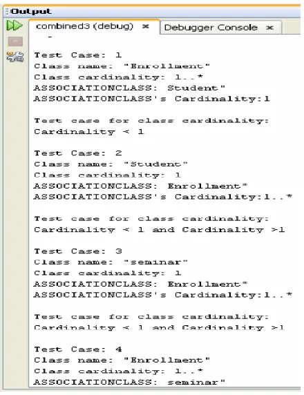
[image:8.595.316.550.462.660.2]The test cases generated by the tool have been shown in the Figure 11. Test cases based on inheritance relation between classes have been shown which one is parent class and which one is child class. Test cases generated for operation of parent class can be applied on child class if child class does not override that operation. Similarly for dependency relationship all test cases derived for a particular operation of a class can be applied to dependent class. Figure 12 shows test cases have been derived on the basis of class cardinality.
[image:8.595.56.294.632.762.2]Figure 12 Test Case Generation Based on Class Cardinality
[image:9.595.320.551.79.466.2]Class name and class cardinality shows a name of the class and its cardinality. Association class and association class cardinality shows name of class and its cardinality which is associated with above stated class. Figure 13 shows test cases based on combination of sequence and statechart diagram. These test cases show Pre-condition, Post-condition, Initial state, final state and test sequence. Figure 14 represents state based partitioning test cases. It describes all operations, their initial state and their final state. Thus all operations that lead to change in state of the system can be identified. Operations that change their state are called state operations and operations that do not change state are called non state operations. It is clear from the figures that test cases that have been generated by the tool are better than the test cases discussed in all the existing work. In previous work related to class diagram test cases has been generated on the basis of class diagram using OCL, but the problem is that these test cases have not been generated automatically. Also test cases depend on class diagram and OCL, thus test cases generated did not tell about initial and final state of the system. Besides, problem is that test cases have been generated from only class diagram. So test cases depend on only static view of system.
Figure 13 Sequence and Statechart Diagram Based Test Case Generation
Figure 14 State Partitioning Based Test Cases
7.
COMPARATIVE ANALYSIS
7.1
Test cases generated from UML
sequence diagram
Manual test cases have been generated from the approach given in the research paper [19]. According to this approach, firstly the sequence diagram is transformed into a graph called SDG (Sequence diagram graph). Then all the paths of this graph are traced at least once to generate the test cases scenarios. From these test scenarios test cases have been generated. Test cases generated are mentioned below:
1) Precondition: “Server is up and application is running” Input: “User enters the URL to open the site”, status=” Browser not responding”
Output: “Abort “
Post condition: “User will be displayed 404 error screen”
2) Precondition: “Server is up and application is running” Input: “User enters the URL to open the site”, status=” Home page not available and browser responding” Output: “Abort “
Post condition: “User will be displayed error message”
3) Precondition: “Server is up and application is running” Input: “User enters the URL to open the site”, status= “user name already exists”
Output: Abort
Post condition: “User will be displayed message user already exists”
4) Precondition: “Server is up and application is running”
Input: “User enters the URL to open the site”, status= “user name < 6 letters”
Output: Abort
Post condition: “User will be displayed message username should be more than 6 letters”
5) Precondition: “Server is up and application is running” Input: “User enters the URL to open the site”, status= “password < 6 letters”
Output: Abort
Post condition: “User will be displayed message password should be more than 6 letters”
6) Precondition: “Server is up and application is running” Input: “User enters the URL to open the site”, status= “user name is available and user name > 6 letters and password > 6 letters.
Output: Return Student ID and registration data
Post condition: User will be displayed congratulations screen.
The test case generated in above scenario does include pre conditions and post conditions from OCL language. Also these test cases include input and output for the particular scenario but these test cases do not include initial and final state of the system as included in Table 1. Though the test cases generated does the complete coverage of sequence diagram so that each path has been traversed at least once but these test cases do not provide the complete picture of the system.
7.2
Test cases generated from UML state
chart diagrams
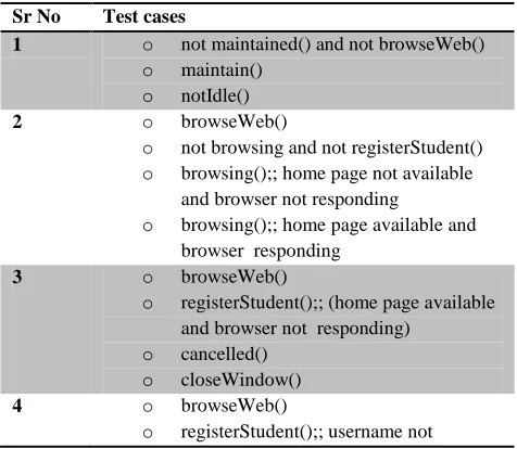
Manual test cases have been generated from the approach given in the research paper [21]. According to this approach, firstly the state chart diagram is transformed into a graph called TFG (Test Flow Graph). Then all the paths of this graph are traced at least once to generate the test cases scenarios. Test Cases generated will be given as below:
Table 7 Test Cases generated from UML state chart diagrams
Sr No Test cases
1 o not maintained() and not browseWeb()
o maintain()
o notIdle()
2 o browseWeb()
o not browsing and not registerStudent()
o browsing();; home page not available and browser not responding
o browsing();; home page available and browser responding
3 o browseWeb()
o registerStudent();; (home page available and browser not responding)
o cancelled()
o closeWindow()
4 o browseWeb()
[image:10.595.310.548.552.759.2]available and username < 6 letters and password < 6 letters
o registerStudent();; username available and username > 6 letters and password > 6 letters
o getSemimarTaken() and getFianlMarks() and getAverageToDate()
o not dropStudent() and not isElligibleToEnroll() and not
checkEligibility() and not addStudent() and notProvideFullName()
o dropStudent();; not eligible
5 o getSemimarTaken() and getFianlMarks() and getAverageToDate()
o isElligibleToEnroll() and
checkEligibility() and addStudent() and ProvideFullName();; eligible
o not idle()
The test case generated provides full coverage of the paths so that each path has been traversed at least once but the test cases do not provide pre conditions and post conditions of the system. Although the test cases provided by these approach ensures 100% test cases coverage but the complete picture of the system is missing for the tester while testing the system.
8.
CONCLUSION AND FUTURE SCOPE
The proposed work has been divided into several modules that perform automated test case generation on UML models. The modules are Petal file reader, SQL *Loader and Test case retrieval. Petal file reader module— this module reads the petal files of class diagram, statechart diagram and sequence diagram. Then tool creates the text files which contain the information extracted from class diagram, statechart diagram and sequence diagram. SQL *Loader—It has been used to store the data into database. Here first tables have been created and then data has been loaded to database. Test case retrieval— in this module IDE has been used to generate test cases. A new algorithm has been proposed to extract information from petal files of Class Diagram, Sequence Diagram and Statechart Diagram. Proposed technique of combining information from combination of UML diagrams is simpler as compared to graphical parsing. Generated test cases are more effective due to: Combining three diagrams to generate test cases, as these test cases include static and dynamic aspects of the system. Also, these test cases show initial state, final state, pre condition, post condition, test sequence, parent-child relationship, cardinalities based test cases, uses relationship based test cases and state based test cases. Further work can be explored to use formal methods to make system suitable for real and large systems. More diagrams can be combined to generate test cases as Use cases can provide user view , activity diagram can give information of flow of control from activity to activity thus represents dynamic aspects of system. Combining all diagrams can result in generation of test cases that are more efficient and effective. Concept of polymorphism can be used to generate automated test cases. UML based integrated test case execution environment is planned for future.
9.
ACKNOWLEDGMENTS
I wish to express my deep gratitude to Dr. Rajesh K. Bhatia, Assistant Professor & Head, Computer Science & engineering
department, Deenbandhu Chhotu Ram University of Science & Technology for providing his uncanny guidance and support throughout the paper.
10.
REFERENCES
[1] Myers, Glenford J. The art of software testing / Glenford J. Myers ; Revised and updated by Tom Badgett and Todd Thomas, with Corey Sandler.—2nd ed.p.cm. ISBN 0-471-46912-2 pp 6
[2] Wang Linzhang, Yuan Jiesong, Yu Xiaofeng, Hu Jun, Li Xuandong and Zheng Guoliang “Generating Test Cases from UML Activity Diagram based on Gray-Box Method” Proceedings of the 11th Asia-Pacific Software Engineering Conference (APSEC’04) pp 284-291 [3] R. S. Pressman. “Software Engineering: A Practitioner’s
Approach”, 6rd Edition, McGraw Hill, New York, 2005, pp. 424, 434, 449.
[4] H.-G. Gross. Measuring Evolutionary Testability of Real-Time Software. PhD thesis, University of Glamorgan, Pontypridd, Wales, UK, June2000.
[5] IEEE. Standard Glossary of Software Engineering Terminology, Volume IEEE Std. 610.12- 1990. IEEE, 1999.
[6] A. Abdurazik and J. Offutt. “Using UML collaboration diagrams for static checking and test Generation”.In International Conference on the Unified Modeling Language (UML 2000), York, UK, October 2000, pp 383- 395
[7] J. Hartmann, C. Imoberdorf, and M. Meisinger. “UML-based integration testing”. In International Symposium on Software Testing and Analysis (ISSTA 2000), Portland, USA, August 2000, pp 60 -70
[8] R. Heckel and M. Lohmann. “Towards model-driven testing”. Electronic Notes In Theoretical Computer Science, 82(6), 2003, pp 33-43
[9] Y.G. Kim, H.S. Hong, D.H. Bae, and S.D. Cha. “Test cases generation from UML state Diagrams”. IEEEProceedings Software, 146(4), 1999, pp 187-192 [10] J. Offutt and A. Abdurazik. “Generating tests from UML
specifications”. In International Conference on the Unified Modeling Language (UML 1999), Fort Collins, USA, October 1999, pp 416-429
[11] John D. McGregor, David A. Sykes “A Practical Guide to Testing Object-Oriented Software”, Addison Wesley, March 05, 2001, pp. 167
[12] Jos Warmer and Anneke Kleppe. “The Object Constraint Language: Precise Modeling with UML”.Boston, MA: Addison-Wesley. 1999.
[13] Q. Nguyen Hung Testing Application on the Web:Test Planning for Internet-Based Systems John Wiley & Sons 2003.
[14] Kirani, S., and W.T. Tsai,”Specification and Verification of Object Oriented programs” Technical Report Tr 94-64, Computer Science Departement, University of Minnesota, Dec 1994.
[16] R. Binder. “Testing Object-Oriented Systems: Models, Patterns and Tools”. Addison-Wesley, 2000.
[17] Philip Samuel, Rajib Mall and Sandeep Sahoo, “UML Sequence Diagram Based Testing Using Slicing”, IEEE Indicon 2005 Conference, Chennai, India, 11-13 Dec. 2005, pp 176-178
[18] Li Bao-Lin, Li Zhi-shu, Li Qing, Chen Yan Hong, “Test Case automate Generation From UML Sequence diagram and OCL Expression” School of Computer Sichuan University, Chengdu 610064, China. pp 1048-52 [19] Monalisa Sarma Debasish Kundu Rajib Mall, “Automatic
Test Case Generation from UML Sequence Diagrams”, 15th International Conference on Advanced Computin and Communications. pp 60-64
[20] P.Samuel R. Mall A.K. Bothra, “Automatic test case generation using unified modeling language (UML) state
diagrams”, IET Softw., 2008, Vol. 2, No. 2, pp. 79– 93/doi: 10.1049/iet-sen: 20060061
[21] Supaporn Kansomkeat and Wanchai Rivepiboon “Automated-Generating Test Case Using UML Statechart Diagrams” Proceedings of SAICSIT 2003 [23] Jonathan Gennick and Sanjay Mishra, Oracle SQL*Loader the Definitive Guide, O’Reilly & Associates, Inc., April 2001, pp 296-300.
[22] Amit Kumar and Rajesh Bhatia, Testing functional requirements using B model specifications. ACM SIGSOFT Software Engineering Notes. Volume 35 Issue 2, March 2010, Pages 1-7