www.ijraset.com Volume 4 Issue XI, November 2016 IC Value: 13.98 ISSN: 2321-9653
International Journal for Research in Applied Science & Engineering
Technology (IJRASET)
Analog Data Signal Compression by using
Differential Pulse Code Modulation with
Microcontroller
Shrenik Suresh Sarade1, Mahesh D. Bhambure2
1,2
Electronics & Telecommunication Department, AITRC, Vita, Sangli, Shivaji University, Kolhapur
Abstract— Compression is a process of converting an input data stream into another data stream that has a small bit size. Compression is take place because of data is normally represented in the computer in a format that is longer than necessary i.e.
the input information has some amount of repetition of data associated with it. The main aim of compression systems is to
eliminate this repeated of data. The idea of speech data compression is to reduce the bit rate for transmission and storage while either maintaining the quality original information. In analog to digital conversion process, we get the sample signal. a high correlation is found between consecutive speech samples. The DPCM algorithm takes advantage of this high correlation property of speech sample data. The DPCM algorithm does not encode the original speech samples. This algorithm takes the difference between a predicted speech sample and the actual speech sample & then encode that difference. This methods do the efficient compression with a significant reduction in the number of bits per sample. Speech signal quality also remains same. Data compression along with analog to digital conversion is an important factor in data Communication and data storage. The Differential Pulse Code Modulation is a technique that gives above mentioned advantages along with Excellent Speech Quality. Keywords— ARM Controller, DPCM Algorithm, Quantizer, Audio Amplifier
I. INTRODUCTION
In the recent years, large scale information transfer by remote computing and the development of massive storage and retrieval systems have witnessed a tremendous growth. To face this problem we need to growth in the size of databases, additional storage devices and the modems and multiplexers have to be continuously upgraded in order to permit large amounts of data transfer between computers and remote centres. Because of this an increase in the cost as well as equipment. One solution to these problems is-“COMPRESSION” where the database and the transmission sequence can be encoded efficiently.
Compression is a process of converting an input data stream into another data stream that has a size is a small. Compression is achieved only because data size is normally represented in the computer in a format that is longer than necessary i.e. the input data has contains amount of redundancy. The objective of compression is to eliminate this redundancy. When compression is used to reduce storage requirements, overall program execution time is also reduced. This is because reduction in storage will result in the reduction access attempts.
With respect to transferring of data, the data (Bit) rate is reduced at the source by the compressor (coder), it is then passed through the communication channel and returned to the original rate by the expander (decoder) at the receiving end. The compression algorithms help to reduce the bandwidth requirements and also provide a level of security for the transmitted data. A combination of coder and decoder is called as codec.
II. COMPRESSIONOFSPEECHSIGNAL
Technology (IJRASET)
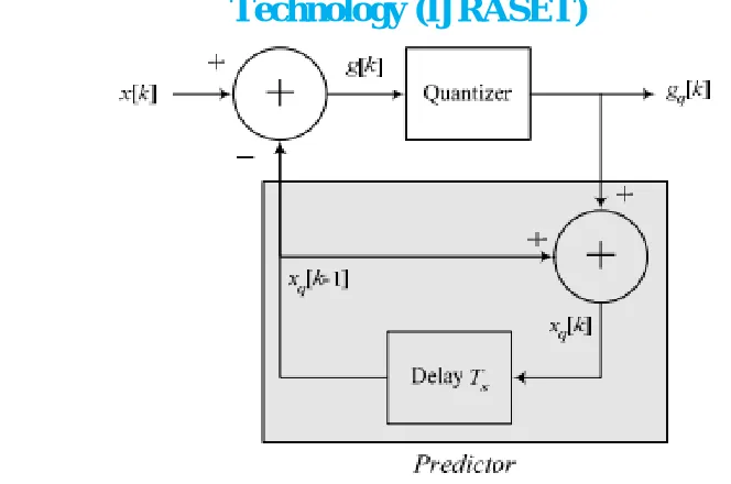
Fig.1 Differential Pulse Code Modulation
In the above system, we can easily prove that the resulting signal Xq[k] is the quantized form of X[k]. First we see that
g[k ] = X [k] − Xq [k −1]
Now, the output of the quantizer is the quantized form of g[k] which can be represented by adding a quantization noise q[k] to the
input of the quantizer. Therefore,
gq[k ] = g[k ] + q[k] Substituting for g[k] in gq[k] gives
gq[k ] = X [k] − Xq[k −1] + q[k]
From the block diagram,
Xq [k] = gq[k ] + Xq [k −1]
= X [k] − Xq[k −1] + q[k] + Xq [k −1] = X [k] + q[k]
So, in fact, the function Xq[k] is the quantized form of X[k] as shown in above equation.
From above we does not mean that if we quantized X[k] directly by the quantizer then we will get Xq[k]. It just says that Xq[k] is a quantized form of X[k].
III. WORKINGBLOCKDIAGRAM
Figure 2 Shows that Hardware diagram of Speech compression by using Differential Pulse Code Modulation.
In following diagram the ARM Controller plays very important role. The ARM Controller contains inbuilt analog to digital conversion & Digital to analog Conversion, also the memory of ARM Controller is sufficient for this project. Because of this we reduces the external hardware.
This project contains the minimum hardware circuit.
A. ARM Controller
B. Mice
C. Audio amplifier
D. Speaker
www.ijraset.com Volume 4 Issue XI, November 2016 IC Value: 13.98 ISSN: 2321-9653
International Journal for Research in Applied Science & Engineering
Technology (IJRASET)
On speaker we listen the original signal sound & Compressed signal sound. We check the quality of original sound & Compressed sound. We compare the original sound waveform & Compressed sound waveform on personal computer.
Fig.2 Speech Compression by using Differential Pulse Code Modulation
IV. RESULTS
When we uses the algorithm of Differential Pulse Code Modulation for compression of signal. We get the quality of original & compressed signal is same on speaker.
We also check the waveform of original & compressed signal.
The Figure 2 shows original sound waveform on DSO. This sound signal amplitude is variable. Sound signal frequency is 20hz to 20Khz. For differential pulse code modulation (DPCM) we required the sample signal for operation. To obtain the correct sample signal we uses the Sampling theorem,
Sampling theorem, Fs > 2Fm
Fs = Sampling Frequency Fm =Original Frequency
Here we sample the original sound signal at 8Khz sample signal.
When we get the sample signal as sampling theorem, then we uses the Differential Pulse code modulation technique for compression.
Fig.4 shows the pulse code modulated sound signal.
Technology (IJRASET)
www.ijraset.com Volume 4 Issue XI, November 2016 IC Value: 13.98 ISSN: 2321-9653
International Journal for Research in Applied Science & Engineering
Technology (IJRASET)
Fig.5 Differential Pulse Code Modulated sound signal of original signal on DSO
V. FLOWCHART
Technology (IJRASET)
www.ijraset.com Volume 4 Issue XI, November 2016 IC Value: 13.98 ISSN: 2321-9653
International Journal for Research in Applied Science & Engineering
Technology (IJRASET)
The Figure 6, 7 & 8 shows flow chart of project. In which Figure 6 shows main project flowchart, figure 7 shows flowchart of between point C & D and figure 8 shows flowchart of between point A & B.
VI. ACKNOWLEDGMENT
We would like to thanks to my guide Mr. D.G.Chougale, Parents, Friend for their valuable suggestions and consistent encouragement.
REFERENCES
[1] Panos E. Papamichalis Ph.D., Practical Approaches to Speech Coding, Prentice-Hall Inc.,Englewood Cliffs, N.J, 1987.
[2] Prentice-Hall, Englewood Cliffs, N.J., Adaptive Differential Pulse-Code Modulation, Digital Signal Processing Applications using the ADSP-2100 Family, Volume 1, Analog Devices,1992.
[3] Rodger Richy Microchip Technology Inc, Adaptive Differential Pulse Code Modulation using PICmicro™ Microcontrollers. [4] L.R. Rabiner and R.W. Schafer, Digital Processing of Speech Signals, Prentice Hall 1978.
[5] B. Smith, “Instantaneous Companding of Quantized Signals”,Bell System Tech. J., Vol. 36, No. 3,pp. 653-709, May 1957. [6] N. S. Jayant, “Adaptive Quantization With a One Word Memory”, Bell System Tech. J., pp. 1119-1144, September 1973 [7] Peter KNAGGS & Stephan Welsh “ARM: Assembly language Programming.
[8] Jayant NS (1974) Digital coding of speech waveforms: PCM, DPCM and DM quantizers.Proc IEEE 62:611–632
[9] Sun L, Ifeachor E (2006) Voice quality prediction models and their applications in VoIP networks. IEEE Trans Multimed 8:809–820 [10] Tremain TE (1982) The government standard linear predictive coding algorithm: LPC-10. Speech Technol Mag 40–49