Power Control of Grid Connected Fuel Cell Based
Generation System
Meenal Sharma1, J. K. Maherchandani2
1, 2 College of Technology and Engineering, Maharana Pratap University of Agriculture and Technology, Udaipur.
Abstract: This paper presents the power control of a polymer electrolyte membrane fuel cell (PEMFC) based grid connected system. Control scheme for inverter control to get the desired active and reactive power output from PEMFC is discussed. A simulation model for PEMFC based Distributed Generation (DG) system has been built in MATLAB/Simulink using Simpower system block-set. Simulation results show that the real and reactive power from the fuel cell DG system to the grid can be controlled in desired manner.
Keyword: Distributed Generation, Polymer Electrolyte Membrane Fuel Cell (PEMFC), Inverter.
I. INTRODUCTION
Fuel Cells are static energy conversion devices which converts chemical energy of its fuel into electrical energy. Polymer Electrolyte Membrane Fuel Cell (PEMFC) are emerging as an attractive power supply source among several types of fuel cells, for applications such as distributed generation power systems and electrical vehicles because of their high reliability, efficiency and cleanness [1]. Fuel-cell power plants can, therefore, becomes a large part of the generation mix in the future for the reinforcement of grid and improving system integrity. Fuel cell distributed generation (FCDG) systems can be placed at any site normally at the distribution level in a power system, this in turn will allow utilities to meet load growth and postpone transmission and distribution network upgrades [2]–[4]. Proper controllers are needed to be designed for FCDG systems when they are to be connected to a utility grid, so that preset amount of real and reactive power may be delivered to the grid or a varying load profile to be supplied [5]. In this paper, power control of grid-connected PEMFC systems is discussed. Simulation models for a PEMFC DG system has been built in MATLAB/Simulink using the Simpower system block-set. Simulation studies are carried out to investigate the real and reactive power controllability of the fuel cell DG systems.
II. SYSTEM DESCRIPTION
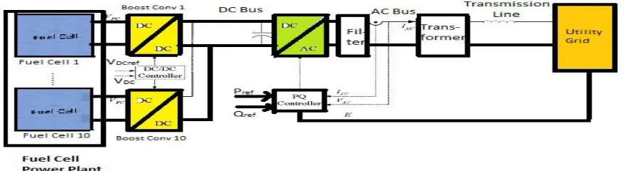
A fuel cell distributed generation system is interfaced with the utility grid through a set of power electronics devices. A pulse width modulated (PWM) voltage source inverters (VSI) and DC/DC Boost converters are used for this purpose. A PWM VSI also serves the purpose of controlling real and reactive power and a DC/DC boost converter is used to adapt the output voltage of each fuel cell array to the dc bus voltage.
[image:2.612.89.528.585.705.2]The PEMFC power plant connects (Fig.1) a number of fuel cell arrays in parallel to get desired power output. Storage device such as super capacitors or battery banks are also connected to the dc bus to provide the storage capability and fast dynamic response to the load transients. To reduce the harmonics introduced by the inverter, a filter is connected to the output of the inverter. Moreover, the real and reactive power (P and Q) flows should follow their respective reference values which can be either any fixed value or to follow a certain load demand. The detail of system parameters are given in Appendix I.
III. POWER CONTROL OF FUEL CELL GENERATION SYSTEM
Real and reactive powers delivered to the utility grid are completely determined by the amplitude and angle of the sending voltage source, i.e. the output voltage of the inverter [6]. On the other hand, if the desired values of real and reactive power are given, the
values of
V
s and
can be determined from (1) and (2):1
2 2
2 2 2
2( ) 2 cos( ) 2 sin( )
s z z
Z
V P Q E PZ QZ
E
(1)
1
cos
cos( )
z z
s s
ZP
E
EV
V
(2)The corresponding dq0 component values of the voltage can be obtained through abc/dq transformation as follows:
1
( )
( )
( )
d a a
q abc dqo b abc dqo b
c c
o
V
V t
V
V
T
V t
T
P
V
V t
V
V
(3)Where
P
1 is the inverse phasor transform. Depending on equations (1)-(3), a desired set of PQ values can be converted intodq
reference voltages to control the inverter.
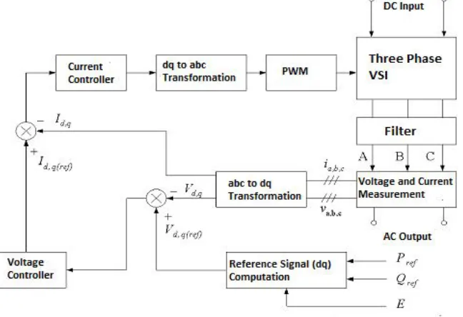
[image:3.612.141.465.475.697.2]The overall control system block diagram for the inverter is given in Figure 2. A two loop control scheme consisting of inner current control loop and outer voltage control loop is adopted for the inverter control. From Fig. 2 the magnitude and angle of the filtered output voltages of the inverter is calculated from the dq reference signal computational block based on equations (1) and (2).The dq reference voltage signals is generated by this block is compared with the actual output voltage in dq frame (Vd,q) which is the output signal of abc/dq transformation block. The output voltage controller then further generates the current reference signals (Id,q(ref)) for the current control loop of the inverter. The dq/abc transformation block takes the dq control signals from the inner current controller loop and converted them back into the abc coordinates. These control signals in abc coordinates are used to modulate the SPWM pulse generator, which produces the proper pulses for the inverter switches and thus the inverter output voltage can be controlled.
IV.SIMULATION RESULTS
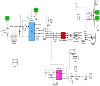
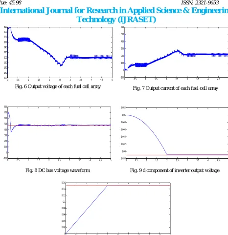
[image:4.612.111.502.192.529.2]A PEMFC DG system has been built in MATLAB/Simulink using the sim power systems block set and shown in Fig. 3. To investigate the power management and load following capability the system is tested under various operating conditions. When the demand of electric power on a utility is heavy, more real power is delivered by the connected DGs to the grid. To help in boosting the grid voltage, there is also a requirement of reactive power which is fulfilled by the DGs. Pref and Qref is set to 370kW and 27kVar respectively. It can be seen from the (Fig. 4 and 5) that the delivered P and Q satisfies their reference values very well. Fuel cell output voltage and currents are shown in Fig. 6 and Fig.7. DC bus voltage waveform is shown in Fig. 8, which shows the constant voltage. Inverter d-q component of output voltage are shown in Fig. 9 and Fig. 10 respectively.
Fig. 3 Developed model of grid connected PEMFC in MATLAB/Simulink environment
0 0.5 1 1.5 2 2.5 3 3.5 4 4.5 5
-0.5 0 0.5 1 1.5 2 2.5 3 3.5
4x 10 5
Fig. 4 P delivered to the grid
0 0.5 1 1.5 2 2.5 3 3.5 4 4.5 5
-2 0 2 4 6 8 10 12 14x 10
[image:4.612.78.541.568.692.2]4
0 0.5 1 1.5 2 2.5 3 3.5 4 4.5 5 120 140 160 180 200 220 240 260 280 300 320
Fig. 6 Output voltage of each fuel cell array
0 0.5 1 1.5 2 2.5 3 3.5 4 4.5 5
-100 0 100 200 300 400 500 600
Fig. 7 Output current of each fuel cell array
0 0.5 1 1.5 2 2.5 3 3.5 4 4.5 5
[image:5.612.69.535.28.509.2]-100 0 100 200 300 400 500 600 700 800
Fig. 8 DC bus voltage waveform
0 0.5 1 1.5 2 2.5 3 3.5 4 4.5 5
1.038 1.04 1.042 1.044 1.046 1.048 1.05 1.052
Fig. 9 d component of inverter output voltage
0 0.5 1 1.5 2 2.5 3 3.5 4 4.5 5
0 0.02 0.04 0.06 0.08 0.1 0.12 0.14 0.16
Fig 40 q component of inverter output voltage
V. CONCLUSION
Control of grid-connected FC DG systems are investigated in this work. A dq transformed two-loop current control scheme is used on the inverter to control the real and reactive power delivered from the fuel cell system to the utility grid. A MATLAB/Simulink model of the proposed FC DG system was implemented using the Simpower system block-set. It is concluded from the simulation results that the real and reactive power delivered from the fuel cell system to the utility grid can be controlled as desired while the DC bus voltage is maintained well within the prescribed range.
REFERENCES
[1] S. V. Khatami, S. Afsharnia, M. R. Haghifam and M. Bahramipanah, "Fuel cell distributed generation system's control in autonomous mode," 2011 2nd Power
Electronics, Drive Systems and Technologies Conference, Tehran, 2011, pp. 123-128.
[2] C. J. Hatziadoniu, A. A. Lobo, F. Pourboghrat and M. Daneshdoost, "A simplified dynamic model of grid-connected fuel-cell generators," in IEEE Transactions
on Power Delivery, vol. 17, no. 2, pp. 467-473, Apr 2002.
[image:5.612.192.419.397.516.2]vol. 11, pp. 741–746, May 1996.
[5] Wang C., Nehrir M.H., and Gao H., June 2006 “Control of PEM Fuel Cell based Distributed Generation System”, IEEE Trans. on Energy Conversion, Vol. 21,
No. 2, pp. 586-595.
[6] M.Hashem Nehrir, Caisheng Wang,”Modelling and Control of Fuel Cells,”John Wiley & Sons, New Jersey.
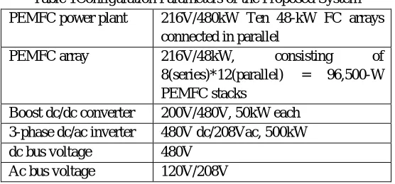
[image:6.612.168.446.162.292.2]APPENDIX I
Table 1Configuration Parameters of the Proposed System PEMFC power plant 216V/480kW Ten 48-kW FC arrays
connected in parallel
PEMFC array 216V/48kW, consisting of
8(series)*12(parallel) = 96,500-W PEMFC stacks
Boost dc/dc converter 200V/480V, 50kW each 3-phase dc/ac inverter 480V dc/208Vac, 500kW
dc bus voltage 480V