Design, Development and Testing of a Novel
Power-Augmented Cross-Axis-Wind-Turbine
Wen Tong
C
HONG1,a,
Wan Khairul M
UZAMMIL1,b,
Kok Hoe
W
ONG1,c,
Bernard Lip Huat SAW
2, Yung Jeh CHU
1,d, Xiao Hang WANG
1,e, Chin-Tsan WANG
31 Department of Mechanical Engineering, Faculty of Engineering, University of Malaya,
50603 Kuala Lumpur, Malaysia, a Corresponding author: [email protected], b [email protected], c [email protected], d [email protected], e [email protected] 2 Lee Kong Chian Faculty of Engineering and Science, University of Tunku Abdul Rahman, Malaysia,
[email protected] 3 Department of Mechanical and Electro-Mechanical Engineering, National Ilan University, Taiwan,
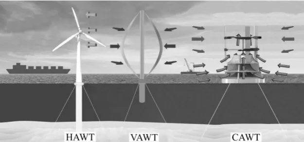
Abstract: The horizontal-axis-wind-turbine (HAWT) is popular in the wind power industry nowadays due to its high power extraction capability. However, the HAWT has some complications due to high turbulent, low speed and changing direction of wind, which inhibits its full performance. Some vertical-axis-wind-turbine (VAWT) designs were able to function well under these wind conditions but they usually produce less power compared to HAWT. Thus, a new type of wind turbine design is proposed to overcome the weaknesses of HAWT and VAWT namely the cross-axis-wind-turbine (CAWT). The CAWT has three vertical and six horizontal blades, which interacts with horizontal and vertical wind. The vertical wind is generated by introducing a deflector or an omni-directional shroud to direct the oncoming horizontal wind towards the horizontal blades. The shroud consists of stacked ring-like deflecting planes supported by vertical webs and an inverted funnel-shaped base. It was designed to produce vertical wind components from any horizontal wind direction. The performance of the shroud was investigated by using a computational fluid dynamics (CFD) software, which showed significant vertical wind component located at the top of the proposed shroud. Experiments using deflectors to guide the oncoming airflow upward were designed to test the CAWT performance with various inclination angles (from 30 to 45°, with 5º increment). The experiments were also conducted with different pitch angles to identify the characteristics of the horizontal blades of the CAWT. A conventional H-rotor VAWT was tested under the same experimental conditions for benchmarking purposes. The results showed that the CAWT produced significant improvements in power output and rotational speed performance compared to the VAWT. It was found that the CAWT’s peak power coefficients (integrated with the 45° deflector) were increased significantly by 103 to 175 % at different tip speed ratios for various horizontal blade pitch angles. The study showed that the proposed CAWT was able to achieve maximum RPM of up to 112% higher than that of the VAWT counterpart as well as better starting behaviour. These preliminary findings show the potential of CAWT for future applications in many locations, creating significant opportunities for wind energy devices.
1. INTRODUCTION
Increasing demand for energy attracts interests of the worldwide researchers on the renewable energy field. As the fossil fuel reserves are depleting, renewable energy could play an important role in energy generation and management. Since 1970s, development of wind turbine technologies saw the evolution of wind turbine designs, strategies and concept brought forward by researchers to optimize the performances of rotors. The most well-known lift-type vertical-axis-wind-turbine (VAWT) that has been used since the 1930’s is the Darrieus wind turbine. Invented by G.J.M. Darrieus, airfoil profile was adopted in the blades of the wind turbine to mimic the wings of birds that has the minimum resistance in forward motion and capable of exploiting maximum available amount of energy by using the traversing thrust of the blades (Darrieus, 1931). Patented in 1931, Darrieus described two major configurations for the wind turbine, curved and straight blades. Over the years, the original two configurations of lift-type wind turbine have evolved into several variations. The development of the curved-blade configuration has evolved into phi-rotor or also known as the egg-beater rotor due to its similarity in geometry. Meanwhile, two different variations of the straight-blade Darrieus turbine have been developed since the 1970’s; notably the variable-geometry (Musgrove-rotor) rotor and variable-pitch (Giromill) rotor. The Musgrove-rotor employed blade-reefing mechanism to limit the speed of the rotor in high wind speed conditions (Mathew, 2006). In its early development, the Musgrove rotor showed good potentials, which led to the building of several large-scale rotors (rated 100 kW). However, due to the complexity of the blade-reefing mechanism and large concrete structure needed to support the rotor result in high production cost and maintenance of the turbine. On the other hand, the giromill is an H-rotor Darrieus wind turbine with variable pitch blades to maintain the angle of attack of the wind interacting with the blades relatively constant in the upwind and downwind regions of the rotor. The method of controlling the pitch blade produced comparable power coefficient as the horizontal-axis-wind-turbine (HAWT). Nevertheless, the mechanism that controls the pitch angle proves costly and unreliable which was difficult to maintain. Therefore, the giromill was abandoned for the much simpler and cost-effective H-rotor (Sjokvist and Eriksson, 2013). The H-H-rotor is a fixed-pitch straight-blade wind turbine that uses a direct-drive generator to provide better cost efficiency since it is positioned near to the ground. Due to the large-scale cyclic torque of the fixed-pitch blade, the rotor shaft is exposed to torsional stress caused by vibration. Therefore, requiring stronger and lighter shaft. Later, the helical H-rotor was developed with a reported power coefficient of 0.3 at tip speed ratio, λ of 3 (van Bussel et al., 2004). The geometry of the helical H-rotor blades distributes the torque uniformly around its circumference, which reduces cyclic forces and lowers the noise level.
Wind energy is recognised as a potential source for free, clean and inexhaustible energy, especially for use in urban cities where it is urged to place wind turbines closer to populated areas due to the decreasing number of economic sites (Wagner et al., 1996). In general, wind farms use large HAWT with long blades, which would generate noise and vibration that are not suitable for urban use. In recent years, small wind turbines have been employed in urban areas for local off-grid applications. Building integrated wind turbines (BIWTs) have shown that the use of wind turbines on buildings has great potential to provide renewable energy and therefore reducing the dependencies on fossil fuel reserves (Balduzzi et al., 2012). However, incorporating wind turbines into buildings possesses several key issues that hinder a wider acceptance of the technology, i.e. concerns on the vibration and noise generated by the wind turbine rotors that would affect the building and its occupants, the visual impact of the rotating turbines on the appearance of the buildings and public safety (Grant et al., 2008). The complex nature of urban winds requires wind turbines that are designed to receive wind from various directions. Moreover, urban winds are generally erratic, insubstantial and inconsistent due to the many obstacles (e.g. buildings and other obstructions); creating blockages that can reduce wind turbine performances (Abohela et al., 2013). Hence, necessitating wind turbines with good self-starting characteristics. Also, researchers over the years have explored the possibilities of augmenting wind flow from the surroundings to increase the oncoming wind speed before it interacts with the turbine blades (Chong et al., 2013). By applying venturi effect, the augmented wind that flows in between buildings, guide-vanes or baffles experiences an increase in velocity, and therefore its’ kinetic energy. Moreover, thoroughly designed guide-vanes could guide the oncoming wind flow to an optimum angle of attack of the blades, hence improving the wind turbine performance.
For a wind energy generation system to be installed in urban areas, several factors need to be considered, i.e. blade failures, noise levels, visual impacts, structural issues, and electromagnetic interference (Oppenheim et al., 2004). Over the years, the HAWTs have been demonstrated to be very effective in generating electricity from the wind. However, the need for a yaw mechanism, the large tower structure supporting the heavy nacelle and the high level of noise hinder the use of HAWTs in urban environments. Due to the disadvantages of the HAWT, the VAWT is deemed to be more suitable to be used in urban areas due to their smaller size and the advantage of producing energy nearer to the consumer (on-site energy generation). Moreover, the VAWT is lighter and safer, and it does not require a yaw mechanism to rotate the VAWT to face the wind direction. Therefore, they can be operated by winds coming from any horizontal direction. Despite the VAWTs general superiority in comparison with the HAWT, the VAWT also has its disadvantages such as the relatively lower efficiency of the Savonius rotor and the poor self-starting capability of the Darrieus rotor.
horizontal blades of the CAWT and the overall performance of the new wind turbine against a conventional VAWT are being investigated. The focus of the current paper is to give an overview of the effects of the deflectors to augment the oncoming wind and direct the airflow towards the central area of the CAWT. For further reading, detailed discussion and investigation of the CAWT can be referred in (Chong et al., 2017a, Chong et al., 2017b, Chong et al., 2016).
2. DESCRIPTION OF THE NOVEL CROSS-AXIS-WIND-TURBINE
The wind characteristics in urban areas are significantly influenced by the roughness of urban settings where there are large densities of high-rise buildings. This produces more complex wind characteristics, where the separation of wind flow is influenced by the buildings in response to the strong multi-directional wind in urban environments. The CAWT has the advantage for turbine performance in a multi-directional wind of urban areas as it can extract wind energy from the horizontal and vertical wind directions. Furthermore, the CAWT can potentially replace the conventional VAWT for urban wind energy system due to its ability to extract wind energy irrespective of the direction of the wind, therefore enhancing the power performance output. The CAWT has three main vertical blades that are connected to six untwisted horizontal blades via specially designed connectors. This arrangement forms the cross-axis-wind-turbine, and it differs from the conventional VAWT where the airfoil-shaped struts will be able to produce lift from the interaction of the vertical airflows. The advantage of the CAWT is its ability to function with airflows coming from the horizontal and vertical directions (see Figure 1), to maximise the wind energy potential.
[image:3.595.105.522.319.515.2]
Figure 1: The general arrangement of the cross-axis-wind-turbine
The horizontal blades act as the radial arms of the CAWT, connecting the hub to the vertical blades. The upper and lower hubs are attached to a central shaft. In total, there are six connectors to link the vertical and horizontal blades together. The current study seeks out the effect of the horizontal blades at different angles on the overall performance of the wind turbine. The design philosophy of the CAWT is to use any vertical wind to interact with the lower and upper horizontal blades to create a larger interaction area (swept area) between the winds and the airfoil. Furthermore, the airfoil-shaped arms enhance the self-starting ability of the CAWT and improve the performance of the entire wind turbine by utilising most of the available energy from the oncoming wind.
2.1. Cross-axis-wind-turbine prototype and lab-scale experimental setup
Wind speed measurements were taken downstream of the fan array, at the centre of the test section by using an anemometer. The wind speed measurements were taken over a 3 x 3 grid of equally spaced points covering a 1.0 m x 1.0 m cross-section at 3.5 m downstream. Careful measurements were taken to reduce uncertainties. The average wind speed for the study was measured to be V∞ = 4.5 ± 0.2 m/s. The experimental rig with deflector (Figure 2) was placed at 3.5 m downstream of the fan array. The deflectors with different angles (30° to 45°, with 5° increment) were placed about 50 mm away from the central axis of the wind turbines. The deflectors guide the oncoming wind and direct the wind upward to the wind turbines. In the study, four different configurations of the CAWT varies in the pitch angle of its horizontal blades (illustrated in Figure 3 and shown in Table 1). The horizontal blades are pitched downward and directly interact with the deflected wind. The deflector’s height, hd
and length, ld dimensions were varied and limited to 350 mm, which is equal to the diameter of the CAWT rotor.
Therefore, the maximum deflector angle for the current study was limited to 45°. Furthermore, the deflector’s distance from the bottom of the turbine generator, yd was set to 50 mm. The wind turbines performances were
[image:4.595.112.454.263.420.2]logged using a dynamometer system in which the recorded parameters for the study are the electrical power, voltage, current, and turbine rotational speed. All the parameters taken from the wind turbines integrated with deflectors were also recorded for bare wind turbines (without deflectors). This is to compare the performance of all the wind turbine configurations.
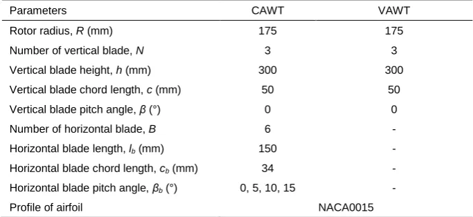
Table 1: The parameters of the study
Parameters CAWT VAWT
Rotor radius, R (mm) 175 175
Number of vertical blade, N 3 3
Vertical blade height, h (mm) 300 300
Vertical blade chord length, c (mm) 50 50
Vertical blade pitch angle, β (°) 0 0
Number of horizontal blade, B 6 -
Horizontal blade length, lb (mm) 150 -
Horizontal blade chord length, cb (mm) 34 -
Horizontal blade pitch angle, βb (°) 0, 5, 10, 15 -
Profile of airfoil NACA0015
[image:4.595.138.450.459.630.2]
Figure 1: The cross-axis-wind-turbine prototype with the experimental rig
As mentioned, the configuration of the CAWT varies in the pitch angle of its horizontal blades. Figure 3 (left) shows one-third of the CAWT, which consists of one vertical blade and two horizontal blades linked by the top and bottom connectors. Various CAWT configurations were used based on the pitch angle, βb throughout the
Figure 3: An illustration of the CAWT prototype showing the connectors, hubs, and blades (left), and the fabricated connectors for the CAWT (right).
2.2. Performance evaluation
To evaluate the performance of the wind turbines, the power coefficient and torque coefficient are presented quantitatively. The power coefficient, CP is used to assess the capability of power generation for a wind turbine.
Defined as the ratio of the shaft power, P generated from the wind turbine to the power available in the wind:
Equation 1: Power coefficient of the wind turbine.
)
5
.
0
(
3=
AV
P
C
P
Where:
− CP = coefficient of power delivered by wind turbines
− P = wind turbine power output (W)
− ρ = density of air (1.225 kg/m3)
− A = turbine swept area (m2) − V∞ = wind speed (m/s)
Torque coefficient, CQ is used to determine the mechanical torque generated by the wind turbine. It is defined as:
Equation 2: Torque coefficient of the wind turbine.
PQ
C
ARV
T
C
=
=
)
5
.
0
(
2where λ is the tip speed ratio, defined by the ratio of the mean blade tip speed to the approaching wind velocity. The ratio is calculated by:
Equation 3: Tip speed ratio of the wind turbine.
=
V
R
Where:
− ω = angular velocity (rad/s)
3. RESULTS AND DISCUSSION
3.1. The effect of deflectors on the performance of the CAWT
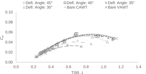
Different aerodynamic effects are observed when the inclination angle of the deflectors is varied. Detailed power coefficients of the 15° and 0° pitch angle CAWTs integrated with different deflectors are shown in Figures 4 and 5, respectively. By analysing the data, it was found that the 15º pitch angle CAWT has the best performance. Moreover, it is observed that by augmenting the approaching wind flow with different inclination angle of deflectors, both the CAWTs have a range of peak power coefficients from 0.0529-0.0785. It is inferred that the deflector guides the deflected airflow towards a better angle of attack as seen by the horizontal blades, therefore better power output is expected. Moreover, the deflected airflow also covers the horizontal blades in the downstream region, therefore creating higher potential of wind energy extraction. From the experiment, the CAWT’s peak power coefficients were increased significantly by 103 to 175 % at different tip speed ratios for various horizontal blade pitch angles when compared to their VAWT counterpart (integrated with the 45º deflector). For further analysis, the data shown in Figure 4 for the 15° pitch angle CAWT integrated with deflector having an inclination angle of 45° produced the highest coefficient of power, CP = 0.0785 at a tip speed ratio of
0.93. In contrast, the bare three straight-bladed VAWT produced a maximum power coefficient of 0.0339 at a tip speed ratio of 0.59. This shows that there is a significant improvement on the power output of the 15° pitch angle CAWT compared to the conventional VAWT where the CAWT produces power 2.3 times higher than the power generated by the VAWT. Note that the graph trend for the bare 15° pitch angle CAWT is almost analogous to that of the VAWT suggesting that without the deflector, the performance of the CAWT is somewhat comparable to the conventional VAWT during operation, although the tip speed ratio range is smaller. Similarly, in Figure 5, the general trend of the CAWT performance with pitch angle of 0° increases when the inclination angle of the deflector is increased. The maximum coefficient of power, CP = 0.0578 at a TSR of 0.7 produced by this CAWT
[image:6.595.136.431.356.508.2]configuration was generated when the turbine is integrated with the 45° deflector.
Figure 4: Power coefficient against tip speed ratio for the CAWT (horizontal blade pitch angle 15°) integrated with deflector having inclination angles, θd = 30°, 35°, 40°, and 45°. For comparison purposes, the bare CAWT
and VAWT power performances are also shown.
Figure 5: Power coefficient against tip speed ratio for the CAWT (horizontal blade pitch angle 0°) integrated with deflector having inclination angles, θd = 30°, 35°, 40°, and 45°. For comparison purposes, the bare CAWT
and VAWT power performances are also shown.
0.00 0.02 0.04 0.06 0.08 0.10
0.0 0.2 0.4 0.6 0.8 1.0 1.2 1.4
CP
TSR, 𝜆
Defl. Angle: 45° Defl. Angle: 40° Defl. Angle: 35°
Defl. Angle: 30° Bare CAWT Bare VAWT
0.00 0.02 0.04 0.06 0.08 0.10
0.0 0.2 0.4 0.6 0.8 1.0 1.2 1.4
CP
TSR, 𝜆
Defl. Angle: 45° Defl. Angle: 40° Defl. Angle: 35°
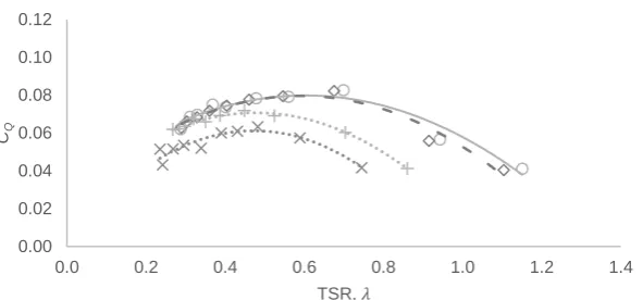
[image:6.595.136.439.571.724.2]One of the most challenging issues associated with wind energy, in particular, the VAWT, is the self-starting capability of the system. For a wind turbine designed to be used in areas experiencing low wind speed, i.e. urban areas and tropical countries, it is essential to conceive a system that can self-start. As mentioned, Darrieus wind turbines have poor self-starting capability compared to the drag-driven Savonius rotor. Over the years, researchers have demonstrated that a proper Darrieus VAWT design can ensure self-starting by lightly loading the turbine, ensuring an optimum number of blades or by exploiting the unsteady tangential force components along the Darrieus turbine circumference (Hill et al., 2009, Worasinchai et al., 2015). Rotor geometry, i.e. chord-to-diameter (c/D) ratio and aspect ratio (AR), is very important in starting performance. Both the CAWT and the VAWT used in the experiment has the same c/D and AR values (0.14 and 6, respectively), and therefore they are geometrically related. With a c/D ratio of 0.14, Worasinchai et al. (2015) have shown that unsteady tangential force can be generated due to a reduced frequency that drives the rotor to self-start. However, the solidity of the machines, in particularly the VAWT, can affect the rotor performances. Unlike the VAWT, the CAWTs use the airfoil-shaped struts to exploit the lift forces. Based on the experiments, this design is advantageous in producing higher torque output. As shown in Figures 6 and 7, the torque coefficients of 15° and 0° pitch angle CAWTs integrated with 45° and 35° deflectors increased significantly as compared to their VAWT counterparts. The maximum torque coefficients produced in the range between 0.0719-0.1085 for both CAWT configurations, which is 13-71% higher than the bare VAWT (CQ = 0.0634). The data suggest that the CAWTs are able to self-start
[image:7.595.164.460.295.440.2]even at lower tip speed ratio, which demonstrates the potential of replacing the conventional VAWT for use in low wind speed regions.
Figure 6: Torque coefficient against tip speed ratio for the CAWT (pitch angle 15°) integrated with deflector having inclination
angles, θd = 35° and 45°. For comparison purposes, the bare CAWT and VAWT power performances are also shown.
Figure 7: Torque coefficient against tip speed ratio for the CAWT (pitch angle 0°) integrated with deflector having inclination
angles, θd = 35° and 45°. For comparison purposes, the bare CAWT and VAWT power performances are also shown.
The rotational speed performances for the wind turbines were taken after a duration of 240 s at a free-running condition where the rotors were only subjected to inertia and bearing friction. Based on the experimental findings, the CAWT with various blade pitch angles integrated with the same deflectors as the VAWT recorded an increased performance in rotor rotational speed by up to 112 %. By analysing the data between the deflector integrated CAWTs and the bare VAWT as shown in Figure 8, the trends of the rotational speed for the wind turbines are steadily increasing and then stabilised after reaching a steady state. For the 15° pitch angle CAWT, by integrating the turbine with the 45° deflector, rotational speed of 348 RPM was obtained, which is the highest rotor rotational speed for the 15° CAWT. In comparison, the bare VAWT recorded a stabilised rotational speed of 240 RPM. Interestingly, the rotational speed of the bare 15° pitch angle CAWT is lower than that of the bare VAWT and some of the other CAWT configuration with lower pitch angles. This may be due to the additional drag
0.00 0.02 0.04 0.06 0.08 0.10 0.12
0.0 0.2 0.4 0.6 0.8 1.0 1.2 1.4
CQ
TSR, 𝜆
Defl. Angle: 45° Defl. Angle: 35° Bare CAWT Bare VAWT
0.00 0.02 0.04 0.06 0.08 0.10 0.12
0.0 0.2 0.4 0.6 0.8 1.0 1.2 1.4
CQ
TSR, 𝜆
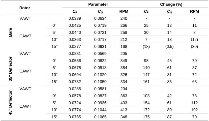
[image:7.595.166.462.493.631.2]impeding the rotational speed of the bare CAWT. The effect of pitch angles on bare configurations of CAWTs is also evident in the torque coefficient graphs shown in Figures 6 and 7, in which the range of tip speed ratio for the bare 15° pitch angle CAWT is smaller than the conventional VAWT. For brevity, some data from the experiment are tabulated in Table 2, which shows the peak power coefficient, torque coefficient, and rotor rotational data.
Figure 8: Rotational speed of the CAWT (pitch angle 15°) integrated with deflector having inclination angles, θd = 30°, 35°, 40°,
and 45°. The bare CAWT and VAWT rotational speed trends are also shown for comparison purposes.
Table 2: Peak power coefficient, torque coefficient, and rotor rotational data
Rotor Parameter Change (%)
CP CQ RPM CP CQ RPM
B
a
re
VAWT 0.0339 0.0634 240 - - -
CAWT
0° 0.0425 0.0719 266 25 13 11
5° 0.0440 0.0721 258 30 14 8
10° 0.0363 0.0717 212 7 13 (12)
15° 0.0277 0.0631 168 (18) (0.5) (30)
3 5 ° D e fl e c tor
VAWT 0.0281 0.0569 205 - - -
CAWT
0° 0.0556 0.0822 349 98 45 70
5° 0.0675 0.0918 384 140 61 87
10° 0.0694 0.1029 326 147 81 72
15° 0.0732 0.1050 334 161 85 63
45 ° D e fl e c tor
VAWT 0.0285 0.0581 204 - - -
CAWT
0° 0.0578 0.0827 363 103 42 78
5° 0.0724 0.0936 433 154 61 112
10° 0.0774 0.1044 413 172 80 102
15° 0.0785 0.1085 348 175 87 70
3.2. Application and impact of the study
Wind augmentation has been shown to increase the performance of wind turbines. Based on the study with deflectors, it was found that the deflectors enhance the power output of the CAWT by creating skewed wind flows to guide the oncoming wind upward to interact with the CAWT rotor. Also, based on the experimental analysis of bare CAWT, without the deflector, the performance of the CAWT is worse than the deflector integrated CAWTs. In the case of the bare 15° pitch angle CAWT, it was found that the turbine performance drops by 18% when compared to the bare VAWT (refer to Figure 4). To illustrate the potential of using a power-augmentation device with the CAWT, a preliminary computational fluid dynamics (CFD) study was conducted to simulate the ability of a shroud to augment the oncoming wind. The shroud consists of stacked ring-like deflecting planes supported by vertical webs and an inverted funnel-shaped base. It was designed to produce vertical wind components from any horizontal wind direction. The wind velocity was set at 8 m/s, with k-omega SST as the turbulence model. Significant vertical wind component located at the top of the proposed shroud was observed as shown in Figure 9. One example of incorporating the existing studies in a large-scale real-world application is in the offshore wind industry. Wind turbines in offshore applications have been deployed in large-scale wind energy production (Borg and Collu, 2015, Vasel-Be-Hagh and Archer, 2017). Similarly, the CAWT has the potential to be deployed to harness offshore wind energy as illustrated in Figure 10. The shroud can be employed as the floating platform for
0 50 100 150 200 250 300 350 400
0 30 60 90 120 150 180 210 240
R
P
M
Time (s)
Defl. Angle: 45°
Defl. Angle: 40°
Defl. Angle: 35°
Defl. Angle: 30°
Bare CAWT
[image:8.595.76.491.324.564.2]the CAWT, in which the oncoming wind can be induced and guided towards the CAWT. Without the shroud, the pitching and rolling motion of the sea waves can also induce periodic tilt angle with respect to the oncoming horizontal wind component, which in turn would interact with the horizontal blades of the CAWT. Moreover, the rapidly changing sea motion with highly varying wind conditions at sea may increase the power output of the bare CAWT. However, the use of the shroud as a platform means the operation of the CAWT is more stable due to the better buoyancy effect of the shroud and its lower centre of gravity.
Figure 9: Preliminary CFD study of a shroud for future integration with the CAWT (Chong et al., 2017b)
Figure 10: Illustration of the proposed CAWT with shroud in offshore application (Chong et al., 2017b)
4. CONCLUSION
[image:9.595.154.467.368.514.2]5. ACKNOWLEDEGMENT
The authors would like to thank the University of Malaya for the research grants allocated (RU018G-2016). Special appreciation is also credited to the Malaysian Ministry of Higher Education, MOHE for the Prototype Research Grant Scheme (PR005-2016) and the Geran Sanjungan Penyelidikan (MO003-2014). The authors would also like to thank the Centre for Research Grant Management Unit, the University of Malaya for the Postgraduate Research Grant (PG052-2014A).
6. REFERENCES
ABOHELA, I., HAMZA, N. & DUDEK, S. 2013. Effect of roof shape, wind direction, building height and urban configuration on the energy yield and positioning of roof mounted wind turbines. Renewable Energy, 50, 1106-1118.
BALDUZZI, F., BIANCHINI, A., CARNEVALE, E. A., FERRARI, L. & MAGNANI, S. 2012. Feasibility analysis of a Darrieus vertical-axis wind turbine installation in the rooftop of a building. Applied Energy, 97, 921-929. BORG, M. & COLLU, M. 2015. Frequency-domain characteristics of aerodynamic loads of offshore floating
vertical axis wind turbines. Applied Energy, 155, 629-636.
CHONG, W. T., FAZLIZAN, A., POH, S. C., PAN, K. C., HEW, W. P. & HSIAO, F. B. 2013. The design, simulation and testing of an urban vertical axis wind turbine with the omni-direction-guide-vane. Applied Energy,
112, 601-609.
CHONG, W. T., GWANI, M., TAN, C. J., MUZAMMIL, W. K., POH, S. C. & WONG, K. H. 2017a. Design and testing of a novel building integrated cross axis wind turbine. Applied Sciences, 7, 251.
CHONG, W. T., MUZAMMIL, W. K., GWANI, M., WONG, K. H., FAZLIZAN, A., WANG, C. T. & POH, S. C. The development and testing of a novel cross axis wind turbine. 3rd AUN/SEED-Net Regional Conference on Energy Engineering, 2016 Yogyakarta, Indonesia. AIP Publishing, 030003.
CHONG, W. T., MUZAMMIL, W. K., WONG, K. H., WANG, C. T., GWANI, M., CHU, Y. J. & POH, S. C. 2017b. Cross axis wind turbine: Pushing the limit of wind turbine technology with complementary design.
Applied Energy, 207, 78-95.
DARRIEUS, G. J. M. 1931. Turbine having its rotating shaft traverse to the flow of the current.
GRANT, A., JOHNSTONE, C. & KELLY, N. 2008. Urban wind energy conversion: The potential of ducted turbines. Renewable Energy, 33, 1157-1163.
HILL, N., DOMINY, R., INGRAM, G. & DOMINY, J. 2009. Darrieus turbines: the physics of self-starting.
Proceedings of the IMechE Part A: Journal of Power and Energy, 223, 21-29.
MATHEW, S. 2006. Wind energy: fundamentals, resource analysis and economics, New York, Springer.
OPPENHEIM, D., OWEN, C. & WHITE, G. 2004. Outside the Square: Integrating Wind into Urban Environments.
Refocus, 5, 32-35.
SJOKVIST, S. & ERIKSSON, S. 2013. Study of demagnetization risk for a 12 kW direct driven permanent magnet synchronous generator for wind power. Energy Science & Engineering, 1, 128-134.
VAN BUSSEL, G. J. W., MERTENS, S., POLINDER, H. & SIDLER, H. F. A. The development of Turby, a small VAWT for the built environment. Global wind energy conference, 2004 Chicago, USA.
VASEL-BE-HAGH, A. & ARCHER, C. L. 2017. Wind farm hub height optimization. Applied Energy, 195, 905-921. WAGNER, S., BAREISS, R. & GUIDATI, G. 1996. Wind turbine noise, Berlin, Springer.
WORASINCHAI, S., INGRAM, G. & DOMINY, R. 2015. The physics of H-Darrieus turbine starting behavior.