© 2015, IRJET ISO 9001:2008 Certified Journal
Page 1054
METAPHORICAL STUDY ON THE PERFORMANCE OF CONTROLLERS IN
MODELING, CONTROL AND SIMULATION OF RENEWABLE SOURCE
BOOST CONVERTER USING MATLAB
G.C.Sowparnika
1, A.Sivalingam
2, M.Thirumarimurugan
31
PG Student (Process Dynamics and Control), Department of Chemical Engineering, Coimbatore Institute of
Technology, Tamil Nadu, India
2
Associate Professor, Department of Chemical Engineering, Coimbatore Institute of Technology, Tamil Nadu, India
3
Associate Professor & Head, Department of Chemical Engineering, Coimbatore Institute of Technology, Tamil
Nadu, India
---***---Abstract
- DC-DC converters are switched powerconverters. The converters are most widely used in research and industrial applications. The DC-DC Boost Converters are used to step-up the supply voltage given to the plant model. The main advantage of using the Boost Converters is that it works in the low voltage according to the design specifications. The DC-DC Boost Converter working is mainly based on the ON and OFF state of the switch. This process is known as the duty cycle. Pulse Width Modulation (PWM) is the technique used as the trigger to produce pulse input to the switch. In order to regulate the uncontrolled supply of voltage, a controller has to be designed and modeled to stabilize the output voltage. The controller is designed to control the duty cycle of the switch which in turn controls the switch ON and OFF state. Since the convectional controllers cannot work under dynamic operating conditions, advanced controllers are to be designed to overcome the problems. In this article, the performance of the convectional controllers and advanced controllers such as Model Predictive Control (MPC), NARMA-L2 Controller, Fuzzy Logic Controller (FLC) and Sliding Mode Controller (SMC) are implemented and
their responses are compared using MATLAB. This
Boost Converter is designed with the renewable source such as solar energy as the input. Solar energy is converted into electrical energy using the solar panels. It is used to control the speed of the universal motor connected to a pump which is used in application such as flow control in Plate Type Heat Exchangers.
Key Words:
Converter, duty cycle, MATLAB, model,
operating condition, renewable source
1. INTRODUCTION
DC-DC boost converters usually provide variations in output voltage with respect to input voltage. The free supply of voltage and current leads to malfunctioning of the boost converter. Control techniques such as analog
and digital methods are used [1]. DC-DC converters are intrinsically non-linear circuits and it is difficult to obtain accurate models which influences dynamic behaviour. The DC-DC converter inputs are generally unregulated DC voltage input and the required outputs should be a constant or fixed voltage. Application of a voltage regulator is that it should maintains a constant or fixed output voltage irrespective of variation in load current or input voltage. Boost converters are widely used for power monitoring of the renewable energy sources such as solar cell, wind mills, wind generators and fuel cell systems. Because of these advantages boost converters are more extensively used in industrial applications. In this article, the comparison of the controllers such as PID, MPC, NARMA-L2, FLC and SMC using MATLAB [2] and the responses are presented.
2. DESIGN OF BOOST CONVERTER
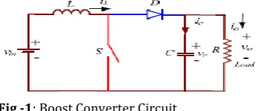
The boost converter is a high efficiency step-up DC/DC switching converter. The converter uses a transistor switch, typically a MOSFET, to pulse width modulate the voltage into an inductor. The necessary parameter for the design of boost converter is the input voltage, output voltage, output current and switching frequency. Fig -1 shows the basic circuit of boost converter [3].
Fig -1: Boost Converter Circuit
Duty Cycle (D): to determine the duty cycle D, for the minimum input voltage. The minimum input voltage is used because it leads to the maximum switching current.
D= 1-
Vin = input voltage
[image:1.595.310.498.597.678.2]© 2015, IRJET ISO 9001:2008 Certified Journal
Page 1055
Vo = desired output voltageLoad Resistance (R):
R= Vo = desired output voltage
Io = desired output current
Inductance (L): L=
Vin = input voltage
Vo = desired output voltage fs = switching frequency
= inductor ripple current Io = desired output current
Capacitance (C): C=
Io = desired output current D = duty cycle
fs = switching frequency = output ripple voltage = inductor ripple current
ESR = equivalent series resistance of the capacitor
Diode: In order to reduce losses, ultra fast recovery diodes can be used. The forward current rating needed is equal to the maximum output current. From the above equations the design parameters are obtained as shown in Table -1.
Table -1: Design Specifications
S.NO PARAMETERS VALUES
1. Input Voltage (Vin) 60 V
2. Input Current (Iin) 5 A
3. Output Voltage (Vo) 300 V
4. Output Current (Io) 1 A
5. Duty Cycle (D) 0.8
6. Load Resistance (R) 300 Ω
7. Inductance (L) 240 mH
8. Equivalent Series
Resistance (ESL) 0.5 Ω
9. Capacitance (C) 5000 μF
10. Equivalent Series
Resistance (ESR) 16 mΩ
*Units: V- volt, A- ampere, Ω- ohms, mH- milli Henry, μF- micro Farad
3. MODELNG OF BOOST CONVERTER (STATE
SPACE AVERAGING TECHNIQUE)
The modeling of DC-DC boost converter is carried out to determine the state space model. The output and the
control transfer function of the system are obtained from the state space model using MATLAB. This method is known as state space averaging technique. The operation of the boost converter takes place in two modes [4]:
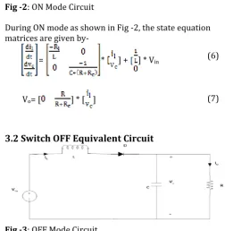
3.1 Switch ON Equivalent Circuit
Fig -2: ON Mode Circuit
During ON mode as shown in Fig -2, the state equation matrices are given by-
= * ] + ] * Vin
Vo= [ ] * [ ]
3.2 Switch OFF Equivalent Circuit
Fig -3: OFF Mode Circuit
During OFF mode as shown in Fig -3, the state equation matrices are given by-
= [ ] * [ ] + ] * Vin
Vo= [ ] * [ ]
The state space parameters A, B, C and D matrices for the above equations are obtained for ON and OFF states. By averaging techniques the determined matrices are: Aavg =
(2)
(3)
(4)
(5)
(6)
(7)
(8)
(9)
(6)
(7)
[image:2.595.303.556.289.548.2]© 2015, IRJET ISO 9001:2008 Certified Journal
Page 1056
Bavg = ]
Cavg = [ ]
Davg = [0]
Using MATLAB, the output transfer function obtained is
4. IMPLEMENTATION OF CONTROLLERS FOR
BOOST CONVERTER
The boost converter should always maintain constant voltage with variations in the input parameters. In order to maintain a stable output in the converter, an appropriate control signal should be applied. In practice the switching network is highly non-linear. An accurate mathematical modeling of the switching network is very difficult to obtain. In addition there are also reported problems of the supply voltage and load current fluctuating over a wide range. A controller is designed and modeled which yields the control transfer function and the controller transfer function. Therefore a real time PID controller is implemented to achieve a proper system performance [5]. The occurrence of oscillatory behaviour of the boost converter is mainly caused by the switching operation of the semiconductor device. In order to stabilize the transient response of the system, PID controller is implemented. Pulse Width Modulation (PWM) technique is the often used switching control
method. Proportional-Integral-Derivative (PID)
controllers are employed for PWM switching control mainly because of its simplicity. By small signal modeling technique, the control transfer function is determined.
4.1 PID Tuning
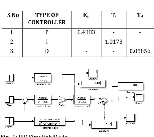
The most widely used tuning method for PID controller is Zeigler-Nichols method. Zeigler-Nichols tuning method is applied to obtain the Kp, Ti and Td values of the closed loop transfer function of the converter [6]. The proportional gain is slowly increased by giving small periodic disturbance to the process. At one point of time, closed loop response tends to produce sustained oscillations and Table -2 shows the tuning parameters. From the oscillations obtained, the ultimate gain (Ku) and the period of oscillation known as ultimate period (Pu) are calculated. Using the values of Ku and Pu, the Kp, Ti and Td parameters are determined. Fig -4 shows the closed loop simulink model [7,8].
Table -2: Tuning Parameters
Fig -4:PID Simulink Model
The transfer function for the compensator is determined as
Therefore the overall control transfer function is
4.1 Model Predictive Control (MPC)
Model Predictive Controller is an advanced technique in process control which is used in process industries such as chemical plants and oil refineries. It is also used in power system models. MPC depends on dynamic models of the process. The advantageous factor is that it predicts the future output with respect to the output obtained from the model and the residues obtained between the plant and model output. Based on the future event, MPC takes the control action accordingly. In order to improvise the performance obtained from PID controller, the MPC is implemented and the output response is shown in the results and discussions. Fig -5 shows the simulink model of the Model Predictive Controller [9].
Fig -5: MPC Simulink Model
S.No TYPE OF
CONTROLLER K
p Ti Td
1. P 0.4883 - -
2. I - 1.0173 -
3. D - - 0.05856
(10)
(11)
(12)
(12)
[image:3.595.308.565.84.312.2] [image:3.595.312.550.624.707.2]© 2015, IRJET ISO 9001:2008 Certified Journal
Page 1057
4.3 NARMA-L2 Controller
NARMA-L2 Controller is also called as Feedback Linearization Control. It is referred to as feedback linearization when the plant model has a particular form (companion form). It is referred to as NARMA-L2 control when the plant model can be approximated by the same form. The central idea of this type of control is to transform nonlinear system dynamics into linear dynamics by cancelling the nonlinearities. Fig -6 shows the simulink model of the NARMA-L2 controller [10].
Feedback linearization (or NARMA-L2) controller is used to identify the system to be controlled. Training a neural network represents the forward dynamics of the system. The first step is to choose a model structure to use. One standard model that is used to represent general discrete-time nonlinear systems is the nonlinear autoregressive-moving average (NARMA) model:
y(k + d) = N[ y(k), y(k- 1), , y(k - n +1),u(k),u(k -1), ,u(k - n +1)]
where u(k) is the system input, and y(k) is the system output. For the identification phase, you could train a neural network to approximate the nonlinear function N. The model output to follow some reference trajectory y(k + d) = yr(k + d),
The nonlinear controller of the model is of the form: u(k) = G[y(k), y(k -1), y(k - n +1), yr (k + d),u(k -1), ,u(k -m +1)]
Fig -6: NARMA-L2 Simulink Model
4.4 Fuzzy Logic Controller (FLC)
PID controller are most widely used controllers and they are widely used in most power electronic closed loop appliances, But in the recent years, the Fuzzy Logic Controller (FLC) are considered to be one of intelligent controllers. This paper is using fuzzy logic controller with feedback of voltage output respectively. The voltage output in the circuit will be fed to fuzzy controller to give appropriate measure on steady state signal [11]. FLC offers an important concept of soft computing with words. It provides technique which deals with imprecision. The fuzzy theory provides mechanism for representation of linguistic terms such as “many,” “low,” “medium,” “often,” “few.” In general, the fuzzy logic provide an inference structure that enable appropriate human reasoning capabilities. Fuzzy logic systems are suitable for
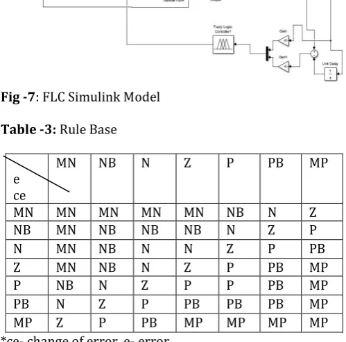
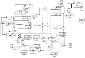
approximate reasoning. Fuzzy logic systems have faster and smoother response than conventional systems and control complexity is less. The fuzzy inference system combines fuzzy IF–THEN rules for mapping from fuzzy sets in the input space X to the output space Y based on fuzzy logic principle. In fuzzy logic, knowledge representation, fuzzy IF–THEN rule is a technique for capturing knowledge that involve imprecision. The main feature of reasoning using fuzzy rules is its partial matching capability, an inference to be made from fuzzy rule even when the rule’s conditions are partially satisfied [12]. Fig -7 shows the simulink model of the FLC. Table -3 shows the rule-base for the boost converter.
[image:4.595.308.558.297.543.2]Fig -7: FLC Simulink Model
Table -3: Rule Base
e ce
MN NB N Z P PB MP
MN MN MN MN MN NB N Z
NB MN NB NB NB N Z P
N MN NB N N Z P PB
Z MN NB N Z P PB MP
P NB N Z P P PB MP
PB N Z P PB PB PB MP
MP Z P PB MP MP MP MP
*ce- change of error, e- error
4.5 Sliding Mode Controller (SMC)
SM controller is a type of non-linear controller. It is employed and adopted for controlling variable structured systems (VSSs). It is very easy to implement as compared to other types of nonlinear and classical controllers [13]. Two important steps in SM control is to design a sliding surface in state space and then prepared a control law to direct the system state trajectory starting from any arbitrary initial state to reach the sliding surface in finite time, and at the end it should arrive to a point where the system equilibrium state exists that is in the origin point of the phase plane. There are three important factors responsible for the stability of SM controllers, existence, stability, and hitting condition. The sliding line divides the phase plane into two main regions. Each region is represent by a switching state and when the trajectory comes at the system equilibrium point, in this case the (14)
(15)
[image:4.595.40.286.464.543.2]© 2015, IRJET ISO 9001:2008 Certified Journal
Page 1058
system is considered as stable system [14]. Fig -8 shows [image:5.595.308.563.71.615.2]simulink model of the sliding mode control technique that operates at infinite switching frequency. But practical SM controllers are operated at finite switching frequencies represent a quasi-sliding mode [15].
Fig -8: SMC Simulink Model
5. SOLAR CELL MODELLING
A solar cell is an electrical device which converts the sunlight directly into electric signals. Solar cells are also called as photovoltaic cells. A couple of these cells together is commonly called as solar panels or photovoltaic panels. The modeling of the solar panel is done to obtain a DC voltage source of 60V using MATLAB [16]. Fig -9 shows the simulink model of PV cell.
Fig -9: Simulink Model of PV Cell
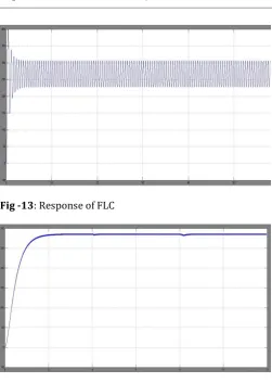
6. RESULTS AND DISCUSSIONS
In this section, the output responses of the convectional and advanced controllers are compared and the response shows that the performance of the boost converter is improved. Fig -10, 11, 12, 13 and 14 shows the response of the controllers.
[image:5.595.50.231.181.305.2]Fig -10: Response of PID
[image:5.595.307.564.362.605.2]Fig -11: Response of MPC
Fig -12: Response of NARMA-L2
[image:5.595.38.284.464.552.2]© 2015, IRJET ISO 9001:2008 Certified Journal
Page 1059
Fig -13: Response of FLCFig -14: Response of SMC
REFERENCES
[1]Sowparnika G C, Sivalingam A and Thirumarimurugan M, “Evaluation of Control Techniques in DC-DC Converters”, International Journal of Emerging Technology & Research, vol.2, no.4, pp.1-8, 2015. [2]Dhivya B S, Krishnan V and Ramaprabha R, “Neural
Network Controller for Boost Converter”, In Proceedings of International Conference on Circuits, Power and Computing Technologies [ICCPCT-2013], pp.246-251, Jan, Research Gate, 2013.
[3]Brigitte Hauke, “Basic Calculation of a Boost Converter’s Power Stage”, Application Report SLVA372C, Texas Instruments, 2014.
[4]Abdul Fathah, “Design of Boost Converter”, Department of Electrical Engineering, National Institute of Technology, Rourkela 2013.
[5]Apekshit Bhowate and Shraddha Deogade, Comparison of PID Tuning Techniques for Closed Loop Controller of DC-DC Boost Converter, International Journal of Advances in Engineering & Technology, vol. 8(1), pp.2064-2073, 2015.
[6] Zeigler J G and Nichols N B, Optimum Settings for Automatic Controllers, Transaction of ASME, vol. 64, pp.759-768, 1944.
[7] Hang C C, Astrom J K and Ho W K, Refinements of Zeigler Nichols Tuning Formula, IEEE Proceedings, vol.138(2), pp.111, 1991.
[8] Astrom K J and Hagllund T, PID controllers Theory, Design and Tuning, 2nd ed., Instrument Society of America, 1994.
[9] Holkar K S and Waghmare L M, An Overview of Model Predictive Control, International Journal of Control and Automation, vol.3(4), pp.47-64, 2010.
[10] Mark Hudson Beale, Martin T. Hagan and Howard B. Demuth, “Neural Network Toolbox- User’s Guide”, MATLAB, The Math Works Inc., 2015.
[11] Rajesh Kr Ahuja and Rajesh Kumar, “Design and Simulation of Fuzzy Logic Controller based Switched-Mode Power Supply”, International Journal of Electrical Engineering, vol.2(5), pp.16-21, 2014. [12] Chetan P. Ugale, R. B. Dhumale and V. V. Dixit, “DC-DC
Converter Using Fuzzy Logic Controller”,
International Journal of Engineering and Technology, vol.2(4), pp.593-596, 2015.
[13]Tamal Biswas, Prof. G KPanda, Prof. P KSaha and Prof. S Das, “Design of PWM-Based Sliding-Mode Control of Boost Converter with Improved Performance”, International Journal of Advanced Research in Electrical, Electronics and Instrumentation Engineering, vol. 4(2), pp. 817-824, 2015.
[14]Hanifi Guldemir, “Study of Sliding Mode Control of Dc-Dc Buck Converter”, Energy and Power Engineering, vol.3, 2011.
[15]R. A. Abdulhalem, Haroutuon A. Hairik, Hisham L. Swady and Asmaa J. Kadhem, “Modeling and Simulation of PWM Sliding Mode Voltage Controller for DC/DC Boost Converters Operating in Continuous Conduction Mode”, Academicia, pp. 1-13.
[16] Natarajan Pandiarajan, Ranganath Muthu,