© 2016, IRJET | Impact Factor value: 4.45 | ISO 9001:2008 Certified Journal
| Page 553
1Pratik Kumar Soni, Student & [email protected]
2
Akashkumar Chavada, student& [email protected]
3
Kartik Parmar, Dept. of Electrical Engineering, TITS, GUJARAT, INDIA
---***---Abstract -
This paper present enhancement of the voltage sag, harmonic distortion and low power factor using DSTATCOM with LCL passive filter in distribution system. This model is based on VSI.D statcom inject the compensating current to the system to mitigate the voltage sag and lcl filter was added to reduce the harmonic distortion. By using phase shift and space vector pulse width modulation technique(svpwm) technique voltage sag can be reduced.
Key Word
)…
voltage source inverter, Voltage
sag,
Dstatcom, phase shift control, svpwm, PI
controller
.
I INTRODUCTION
An increasing demand for high quality, reliable electrical power and increasing number of distorting loads may leads to an increased awareness of power quality both by customers and utilities. The most common power quality problems today are voltage sags, harmonic distortion and low power factor.
Voltage sags is a short time (10 ms to 1 minute) event during which a reduction in r.m.s voltage magnitude occurs [4]. It is often set only by two parameters, depth/magnitude and duration. The voltage sags magnitude is ranged from 10% to 90% of nominal voltage and with duration from half a cycle to1 min.Voltage sags is caused by a fault in the utility system, a fault within the customer’s facility or a large increase of the load current, like starting a motor or transformer energizing [2,3].Voltage sags are one of the most occurring power quality problems. For an industry voltage sags occur more often and cause severe
problems and economical losses.
Utilities often focus on disturbances from end-user
equipment as the main power quality problems
[5].Harmonic currents in distribution system can cause
harmonic distortion, low power factor and additional
losses as well as heating in
the electrical equipment. It also can cause vibration and noise in machines andmalfunction of the sensitive equipment. The development of power electronics devices such as Flexible AC Transmission System(FACTS) and customs power devices have introduced and emerging branch of technology providing the power system with versatile new control capabilities [1].There are different ways to enhance power quality problems in transmission and distribution systems. Among these, the D-STATCOM is one of the most effective devices. A new PWM-based control scheme has been implemented to control the electronic valves in the DSTATCOM.The D-STATCOM has additional capability to sustain reactive current at low voltage, and can be developed as a voltage and frequency support by replacing capacitor with batteries as energy storage. [6, 7]
In this paper, the configuration and design of the DSTATCOM with LCL Passive Filter are analyzed. It is connected in shunt or parallel to the 11 kV test distribution system. It also is design to enhance the power quality such as voltage sags, harmonic distortion and low power factor in distribution system.
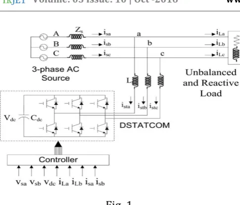
II SYSTEM CONFIGURATION
© 2016, IRJET | Impact Factor value: 4.45 | ISO 9001:2008 Certified Journal
| Page 554
Fig. 1.
A. Voltage Source Converter (VSC)
A voltage-source converter is a power electronic device that connected in shunt or parallel to the system. It can generate a sinusoidal voltage with any required magnitude, frequency and phase angle. The VSC used to either completely replace the voltage or to inject the ‘missing voltage’. The ‘missing voltage’ is the difference between the
Nominal voltage and the actual. It also converts the DC voltage across storage devices into a set of three phase AC output voltages [8, 9].
In addition, D-STATCOM is also capable to generate or absorbs reactive power. If the output voltage of the VSC is greater than AC bus terminal voltages, D-STATCOM is said to be in capacitive mode. So, it will compensate the reactive power through AC system and regulates missing voltages. These voltages are in phase and coupled with the AC system through the reactance of coupling transformers. Suitable adjustment of the phase and magnitude of the DSTATCOM output voltages allows effectives control of active and reactive power exchanges between D-STATCOM and AC System. In addition, the converter is normally based on some kind of energy storage, which will supply the converter with a DC voltage [10].
B. Controller
The principle drift of the control method is to preserve continuous voltage magnitude at the place where a sensitive load is coupled, beneath system cohibitions. RMS voltage at the load point is measured in this control technique, i.e. there is no.
Requirement of reactive power measurements. for switching of VSC sinusoidal PWM scheme is utilized as sine PWM bears simple and quick reflection compared to other methods of PWM such as space vector PWM.
From the RMS value of reference voltage and RMS value of terminal voltage an error signal is generated which is fed to the controller. This error signal is processed by PI controller and output angle δ is generated, which is applied to the PWM signal generator. Phase angle of the balanced supply voltages which is assumed to be 1200 summed with the angle of the output of PI to produce the desired synchronizing signal required to operate the PWM generator. Here in converter, there is both active and reactive power exchange takes place simultaneously. Now the error signal is obtained by comparison of the reference voltage with the RMS voltage measured at the load point. this error signal is processed by the PI controller which in return generates the required angle to drive the error to zero, I.e., the load RMS voltage is brought back to the reference voltage.
D. LCL Passive Filter
LCL Passive filter is more effective on reducing harmonic distortion. To design it, equation (2.3), (2.4) and (2.5) are used.
© 2016, IRJET | Impact Factor value: 4.45 | ISO 9001:2008 Certified Journal
| Page 555
Figure 2.circuit diagram for single phase LCL Passive Filter
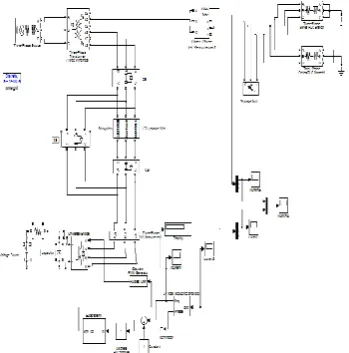
C. Simulink Model for the test system
The test system was design using MATLAB simulink is shown in figure below.
To create distortion in the distribution system, different types of fault such as Three Phase to Ground (TPG), Double Line to Ground (DLG), Line to Line (LL), and Single Line to Ground (SLG) are injected.
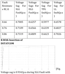
[image:3.595.311.555.233.526.2]1. without insertion of D-STATCOM
TABLE. RESULTS OF VOLTAGE SAGS FOR DIFFERENT TYPES OF FAULT
Fault Resist ance Rf, Ω
Voltage Sag For SLG Fault(p.u)
Voltage Sags For
DLG Fault(p.u)
Voltage Sag For TPG fault(p.u
)
Voltage Sag For
LL fault(p.u)
0.66 0.7005 0.6257 0.5977 0.6578
different types of fault. From the table, it can be observed that when the value of fault resistance is increase, the voltage sags will also increased for different types of fault.
A. without insertion of DSTATCOM
. [Fig
Voltage sag is 0.7005p.u during SLG fault without DSTATCOM]
[Fig. Voltage sag is 0.6257p.u during DLG fault without
DSTATCOM
[image:3.595.39.214.356.533.2]© 2016, IRJET | Impact Factor value: 4.45 | ISO 9001:2008 Certified Journal
| Page 556
[Fig . Voltage sag is 0.6578p.u during LL fault without
DSTATCOM]
Table shows overall results of voltage sags in p.u for different types of faults. From the table, it can be observed that the value of fault resistance is increase, the voltage sags also increased for different types of fault.
Fault Resistanc e Rf, Ω
Voltage Sag For SLG Fault(p.u )
Voltage Sags For DLG Fault(p.u )
Voltage Sag For TPG fault(p.u )
Voltage Sag For LL fault(p.u )
0.66 0.7005 0.6257 0.5977 0.6578
0.76 0.7109 0.6566 0.6339 0.6827
0.86 0.7319 0.6809 0.6623 0.7026
B.With Insertion of DSTATCOM
[Fig. Voltage sag is 0.9342p.u during SLG Fault with
DSTATCOM]
[Fig. Voltage sag is 0.9308p.u during DLG Fault with
DSTATCOM]
[Fig. Voltage sag is 0.8949p.u during TPG Fault with
DSTATCOM]
[Fig. Voltage sag is 0.9627p.u during LL Fault with DSTATCOM]
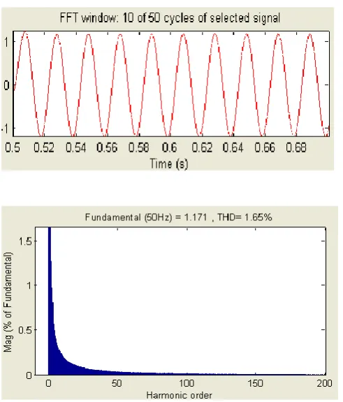
[image:4.595.33.293.304.599.2]Figure. Waveform of distortion output current without LCL Passive Filter
[image:4.595.237.551.368.696.2]Figure shows the waveform of distortion output Current and figure shows the spectrum of distortion output current.
[image:4.595.305.555.373.457.2]© 2016, IRJET | Impact Factor value: 4.45 | ISO 9001:2008 Certified Journal
| Page 557
Figure. .harmonic spectrum of output current with LCL Passive Filter
VIII CONCLUSION
The simulation results show that the voltage sags can be mitigate by inserting D-STATCOM to the distribution system. By adding LCL Passive filter to D-STATCOM, the THD reduced within the IEEE STD 519-1992. The power factors also increase close to unity. Thus, it can be concluded that by adding D-STATCOM with LCL filter the power quality is improved.
VI. REFFERENCES
[1] A.E. Hammad, Comparing the Voltage source capability of Present and future Var Compensation Techniques in Transmission System, IEEE Trans, on Power Delivery. Volume 1. No.1 Jan 1995.
[2] G.Yalienkaya, M.H.J Bollen, P.A. Crossley, “Characterization of Voltage Sags in Industrial Distribution System”, IEEE transactions on industry applications, volume 34, No. 4, July/August, PP.682-688, 1999
[3] Haque, M.H., “Compensation Of Distribution Systems Voltage sags by DVR and D-STATCOM”, Power Tech Proceedings, 2001 IEEE Porto, Volume 1, PP.10-13, September 2001.
[4] Anaya-Lara O, Acha E., “Modeling and Analysis Of Custom Power Systems by PSCAD/EMTDC”, IEEE Transactions on Power Delivery, Volume 17, Issue: 2002, Pages: 266-272.
[7]Tejas Zaveri ,Bhalja Bhavesh, and NaimishZaveri, “Control Techniques for Power Quality Improvement in Delta Connected Load using DSTATCOM”, IEEE International Electric Machines & Drives Conference (IEMDC), 2011, pp. 1397-1402.
[8] Noramin Ismail, Wan Norainin Wan Abdullah, “Enhancement of Power Quality in Distribution System Using D-STATCOM”, IEEE Transactions on Power Delivery, Nov, 2010, pp.418-423.
[9]Hirak K. Shah, P.N. Kapil, and M.T.Shah, “Simulation & Analysis of Distribution Static Compensator (D-STATCOM)”, IEEE Transactions on Power Delivery, Dec 2011.
[10]Pradeep Kumar, “Simulation of Custom Power Electronic Device DSTATCOM–A Case Study”, IEEE Transactions on Power Delivery, 2011