© 2016, IRJET | Impact Factor value: 4.45 | ISO 9001:2008 Certified Journal
| Page 1274
A Review Paper on PLC Based Automatic Fly Ash Brick Machine
Bhupendra Singh
1, Arun Kumar
21
M-Tech scholar, E&TC department, Bhilai institute of technology, Chhattisgarh, India
2Associate Professor, E&TC department, Bhilai institute of technology, Chhattisgarh, India
---***---Abstract -
Production of ash brick is an alternativeutilization of fly ash. A most important part of the Fly Ash Bricks plant is Pan Mixer and molding machine. This study mainly focused on the Brick Molding Mechanism. . There are so many methods for molding of bricks, but here we have used only hydraulic compression method which is more efficient and reliable method. The pressing machine has three sets of brick moulds which are 120º apart from each other. One set of mould receive the mixture, then it is compressed and finally two bricks are made in one revolution of this machine. This paper is basically based on the saving of unnecessary economical losses and provided safety for plants workers and increases the efficiency of bricks industry. For this we have implemented this mechanism through Programming Logic Controller (PLC).
Key Words:
Programming Logic Controller, Hydraulic
Machine, Gear motor etc…
1. INTRODUCTION
These days India is witnessing a new phase in development with rapid economic growth and high rate of urbanization. In India the estimation of total fly ash generation from thermal power plants is at about 60 million tons per year, which may increase to about 110 million tons per year by 2015, therefore the use of fly ash for the production of bricks as an alternative utilization of fly ash. Essentially, the only solid ingredient of the bricks is the ash and the liquid ingredient is water. Many studies have been conducted on cement and concrete applications which were authorized and federally approved. The use of fly ash for the production of bricks is an alternative utilization of fly ash. Fly ash itself can be used for the brick-making since it contains suitable ceramic characteristics and properties. Other ingredients that so far are commercially protected are cheap, commonly available and, though essential, are only minor quantities.
1.1 Brick Making Plant
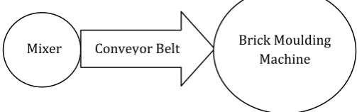
The bricks making technology includes the method of mixing, forming into moulds, curing, drying, sorting for testing and dispatching. A most important part of the Fly Ash Bricks plant is Pan Mixer and molding machine. The raw materials are mixed in the mechanized pan mixer. One inclined conveyor belt is fitted in between pan mixer and pressing machine to convey the mixture of raw materials to the pressing machine. There are two methods of brick making mechanism. One is Hydraulic press and the other is Vibro press, but we are using only hydraulic compression method which is more efficient and reliable method. The pressing machine has three sets of brick mould. One set of mould receive the mixture, then it is compressed by hydraulic and finally two bricks are made in one revolution of this machine
Fig -1: Basic brick making process
1.2 Basics of PLC
A Programming Logic Controller or PLC or Programmable Controller is a digital computer used for the automation of typically electro-mechanical processes. For example control of machinery on factory assembly lines, amusement rides or light fixtures. PLCs are designed for multiple analogue and digital inputs and output arrangements, extended temperature ranges, immunity to electrical noise, and resistance to vibration and impact. Programs to control machine operations are typically stored in non-volatile memory. A PLC is an example of a "hard" real-time system as the output results must be produced in response to input conditions within a limited time, otherwise unintended operation will result.
[image:1.595.309.561.457.536.2]© 2016, IRJET | Impact Factor value: 4.45 | ISO 9001:2008 Certified Journal
| Page 1275
1.3 Problems Background
In bricks manufacturing industry there is a common problem that is lack of communication and sudden fault that occurred in machine. In industry a loud sound produced when machine is running so some time works cannot hear proper command to on or off that cause of accident. These accidents creates economical problem. Second issue is that in traditional bricks making plant mixing and molding process are done by manually which is time consuming process. So this operating procedure should be automatic. That improve safety efficacy of plant without change their basic ruining procedure.
1.4 Objective of the Work
Basic objective of this thesis is to develop a fully automated model of fly ash brick making machine. This will reduce the communication gap and mismanagement of bricks plant. Less numbers of man powers is required and hence increases the speed and efficiency of production.
2. METHODOLOGY
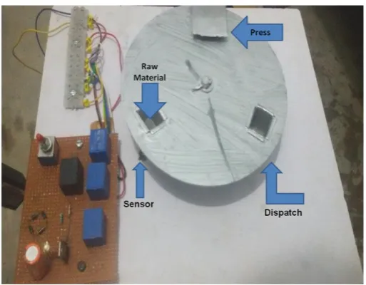
The work is mainly focused on fly ash brick moulding mechanism. There are two methods of brick making mechanism. One is Hydraulic press and the other is Vibro press, but we are using only hydraulic compression method which is more efficient and reliable method. The pressing table is circular having three sets of brick moulds each 120° apart. One set of mould receive the mixture, then it is compressed by press hydraulic and after moulding of brick dispatch hydraulic ejects the moulded brick from the mould. All these processes of filling of moulds, pressing of material and dispatching of moulded bricks for one revolution are done same time. In this way two bricks are made in one revolution of this circular table.
2.1 Hardware Description
Hardware description includes block diagram of the complete process and circuit diagram of the different electrical connections.
Fig -2: Block diagram of the model
Fig -3: figure of the model of moulding machine
Following are the main components of the model proposed.
Main motor (Chuck Motor): It is nothing but a DC gear motor. A gear motor can be either an AC (alternating current) type or a DC (direct current) type electric motor. A gear motor is a specific type of electrical motor that is designed to produce high torque while maintaining a low horsepower, or low speed, motor output. Gear motors are commonly used in devices such as can openers, garage door openers, washing machine time control knobs and even electric alarm clocks.
Hydraulics System (Press &Dispatch): In the model of proposed machine we are using electro-mechanical
Power Supply
Chuck
Motor Hydraulic Press Hydraulic Dispatch
ON/OFF Switch
Sensor
[image:2.595.310.557.99.297.2] [image:2.595.308.565.330.530.2]© 2016, IRJET | Impact Factor value: 4.45 | ISO 9001:2008 Certified Journal
| Page 1276
hydraulic press. It mainly works on the principle of shadedpole mechanism.
Fig -4: Electrical Hydraulic Mechanism.
In this mechanism a fiber pole is considered which is coated by iron sheet on its 2/3 portion. Fiber end of the pole is free and Iron coated end is connected to a spring mechanism which due to which pole comes to its original position. Also a fiber bobbin is used on which winding is wrapped. A supply of 230V A.C is applied across the winding, resulting in magnetic field inside the bobbin. Due to this magnetic field N-S pair is created. Due to AC excitation iron shaded portion of the pole acting as electromagnet and the opposite polarities i.e. S-N are created on it. According to magnetic property opposite polarities attracts each other.
Therefore, every time when ac excitation is given to winding, polarities of field attracts the polarities of pole and pole comes out through the bobbin as hydraulic press or hydraulic dispatch form open end. In case of no supply magnetic field disappears and pole comes to its previous position due to spring mechanism.
IR Sensor: The proximity sensing uses an external, pulsed infrared LED source to emit controlled amounts of infrared radiation. When an external object reflects back some of this infrared radiation back to the IC, it is detected by the integrated light detector. The amount of reflected light detected is then used to determine the object’s proximity to the sensor
Proposed method is completely automatic and is controlled by PLC programming. Flow of the process can be explained as:
i. Switch on the power supply
ii. Main motor starts and rotate the circular table iii.Sensor start sensing for the Mould
a. Stops the motor when mould is present b. Keep sensing until mould is present
iv.As motor stops, timer TON is turned on for required time
v. Both the hydraulic are pressed simultaneously until timer is up
a. Keep pressed till timer is on
b. As timer times up, hydraulics are released vi.Starts the chuck motor again
Process explained above will be continued automatically till power switch is on.
2.2. Software Description
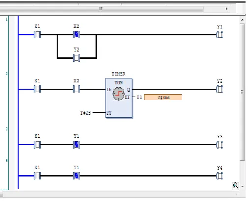
This automatic process is done by the PLC programming. The programming done in PLC is called Ladder Programming. Ladder Diagrams are similar to relay logic diagrams that represent relay control circuits. A program written in Ladder Diagram language is composed of rungs which are sets of graphical instructions drawn between 2 vertical potential bars. The rungs are executed sequentially by the logic controller.
Fig -5: Ladder diagram of the complete process
Timer TON is used in the programming. It is the flexibility that we can increase or decrease the time of hydraulic action by the timer. Also output of the timer is used to stop or run the main motor.
3. RESULTS
[image:3.595.39.268.130.283.2] [image:3.595.309.562.407.612.2]© 2016, IRJET | Impact Factor value: 4.45 | ISO 9001:2008 Certified Journal
| Page 1277
properly. It shows that there is no difficulty to run ourhardware and software.
Table -1: Outputs at different rpm
S.No. motor (rpm) Speed of moulds No. of bricks No. of /rotation
Total Bricks (8 hrs)
1. 3 3 3 4320
6 6 8640
2. 5 3 3 7200
6 6 14,400
From the above table we can draw a remarkable conclusion that
No. of bricks α No. of Moulds & rpm of motor From the above relation we can see that how we can increase the efficiency of the model.
Table -2: Boolean output for the different process
INPUTS OUTPUTS
X 1 (sw it ch ) X 2 (S enso r) Y2 (T imer outp u t) Y1 ( Mo tor ) Y3 (Hyd ra u lic Pre ss ) Y4 (Hyd ra u lic D isp at ch )
0 0 0 0 0 0
1 0 0 1 0 0
1 1
0 (Till timer is up)
0 1 1
1 0 1 1 0 0
1 1 0 0 1 1
1 1 0 (up) 0 1 1
The above process will goes on till we do not press the input switch.
Table -3: Comparison with the existing method
S.
No. Features
Proposed method
Existing method
1. Time
Time saving ( Material filling ,
pressing & ejection simultaneously ) Time consuming (One process
at a time)
2. Capacity 8000-10,000 bricks per day
5000-6000 bricks per day
3. Manpower
Manpower reduces (2-3 person) Manpower is needed for every process (5-8 person) 4. Safety and fault diagnosis
Safe and easier (PLC operated)
Less safe and faulty due to contactor
relays
5. Nos. of moulds
Can be increased by changing the
die.(3,6,9.. as available)
Not such option available
6. Costing
Installation cost is high but running
cost is cheaper
Installation cost is cheaper
but running cost is high
7. Operation Automatic based on ladder programming
Hydraulics are operated manually
4. CONCLUSIONS
© 2016, IRJET | Impact Factor value: 4.45 | ISO 9001:2008 Certified Journal
| Page 1278
machine. Thus, by implementation of this model efficiencyis increased. Complete system is automatic. The accident cases also reduce.
REFERENCES
[1] Kendesarin Pimraksa, Matthias Wilhelm and Michael kochhberger,” A New Approach to the Production of
Bricks Made of 100% Fly Ash, International Ash
Utilization Symposium, University of Kentucky, 2001. [2] Obada Kayali, “High Performance Bricks From Fly
Ash”lecture notes, Lexington, Kentucky,USA, 2005. [3] Ankit H Parmar, Kinnarraj P Zala, Ankit R Patel,
“Modification of Foremost Element of Hydraulic Press Machine”, IJASTR,vol. 3, june 2014.
[4] A. Sumathi, K. Saravana Raja Mohan, “Compressive Strength of Fly Ash Brick with Addition of Lime, Gypsum and Quarry Dust”, IJCRGG, Vol. 7, pp 28-36, 2014-2016.
[5] Cockrell, L. Sander, T.M. Holnan Inc., Dundee, MI.,” Process control in cement industry”, IEEE Transaction, vol-28, pp: 945 – 953, 2006.
[6] Prime, J.B. Valdes, J.G, “use of ladder diagram in discrete system of PLC,” IEEE Transaction, vol. PAS-100, pp- 143 – 153, January 1989.
[7] N.Gangadhar Reddy,” High Capacity Fly Ash Bricks & Blocks Unit, “A project report, May 2014.
[8] Ravi Masand, Prof. S.P Shukla,” PLC and SCADA based Fault Diagnosis of Induction Motor”, IJDACR, Vol. 2, January 2001.