2702
Abstract — This paper consists of the redesign, analysis, synthesis and experimental verification of the grinding wheel for fly ash grinding machine. Grinding wheel was designed to take up the forces required to grind fly ash of 250 microns to 50 microns size. Grinding wheel also considered to take centrifugal force generated due to 238 rpm of central shaft and 900 rpm of shaft of wheel. The mathematical calculations of various stresses due to dynamic loading conditions on grinding wheel of fly ash grinding machine is carried out. Contact stress in grinding wheel and race is very prominent parameter of grinding wheel design. Generation of 3D CAD model in CAD software with exact dimensioning and according to manufacturing process of fly ash grinding wheel is considered. The analysis on ANSYS software with exact loading condition is carried out. In this paper, numerical analysis (FEA) of contact stress for grinding wheel is studied by finite element method (FEM). Stress analysis is carried out to find out highly stressed components of grinding wheel which are prone to failure. Verification of Stress on grinding wheel by analytical tool is performed. The parameters for study of comparison are selected as vibration and temperature. On completion of analysis, experimentation and comparison suitable correction is suggested. Verification of improved design is carried out.
Index Terms – Fly Ash Grinding Roller, Contact Stress, CAD, Ansys
I. INTRODUCTION
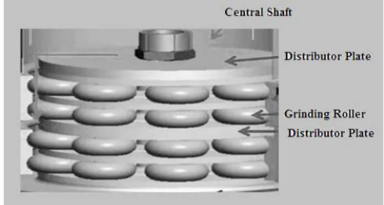
Floating roller grinding machine is the special sort of grinding machine used to grind fly powder from material after burning (fly ash).[1] In floating roller grinding machine rollers are subjected to high pressure and this high pressure is used to grind the fly ash particles.[2] Power is supplied to the central shaft of floating roller grinding machine with the help of electric motor followed by gearing unit. Central shaft rotate with 238 rpm. Floating roller grinding machine consist of four stages of grinding rollers. Each stage consists of top and bottom separator plates six rollers are secured in between top and bottom turn plates. Six in each stage and total 4 stages i.e. total 24 floating rollers used to grind fly ash. Roller assembly
This work was supported in part by Mechanical (Design) Engineering Department in JSPM’s RSCOE, Tathwade, Savitribai Phule Pune University. Mr. Prasad Patil is Post Graduate student the JSPM’s RSCOE, Tathwade, Pune, India,+91-8857928178
Prof. M. S. Ramgir is with the JSPM’s RSCOE, Tathwade, Pune, India, +91-9702995349.
secured in top and bottom turn plate with the help of shaft grooved at both the ends. Two bearings are mounted on the shaft to support outer cylindrical roller. Top and bottom roller plates are bolted to seal the bearing lubrication. Oil seals are also used to avoid leaking of oil from roller assembly. Grinding roller rotate inside stationary outer cylindrical race and fly ash is ground in between roller and outer cylindrical race to give fine fly ash powder. In this paper study of failures
and faults in the previous design and analysis to avoid failures are carried out. Following shows the schematic diagram of the fly ash grinding machine.
A. Problems in initial design of roller
1. Two spherical roller bearings were used to transfer load and smooth motion of roller. Spherical roller bearings are failing after some time of operation. Technical bearing mounting technique was not used while assembling the roller hence it leads to loose fit with shaft and hence high amplitude vibrations are generated in the machine.
2. Axial force on the shaft is not considered while selecting bearing hence it is one of the reasons of bearing failure.
3. Separate grinding liner was used of same material as of inner cylindrical roller. Grinding linear was fitted with the help of withdrawal sleeve and locknut. After some period time as grinding progress due to some wear grinding liner and inner roller fit become loose and hence it leads to vibration and unnecessary stresses in the roller.
Single intact roller is used in fly ash grinding machine hence roller is redesigned to eliminate grinding liner. Shaft is redesigned as per new bearing selection and axial force to reduce failures vibrations and operating temperature rise.
Design and Analysis of Grinding Wheel of Fly
Ash Grinding Machine
Mr. Prasad P. Patil, PG Student, Prof. Milind Ramgir, Associate Professor, JSPMs RSCOE Tathwade
II. DESIGN CALCULATIONS
A. Forces and Angular Velocities of Grinding Roller 1. Bond Work Index (for < 3.36 mm particle size) [3] 𝑊𝑖,𝐵 = 4.9 𝑥𝑚𝑎𝑥0.23∗𝐺0.82∗( 1 𝑥 80− 1 𝑋 80) [𝑘𝑊] (1) 𝑊𝑖,𝐵 = 0.0835 [𝑘𝑊]
2. Energy (E) required to grind fly ash is calculated by multiplying work index and feed rate per seconds.[4][5]
𝐸 = 𝑊𝑖,𝐵∗ 𝑓𝑒𝑒𝑑 𝑟𝑎𝑡𝑒 𝑝𝑒𝑟 𝑠𝑒𝑐𝑜𝑛𝑑𝑠 (2) 𝐸 = 835.305 𝑘𝐽/𝑠
3. Angular velocity along central shaft in rad/s[10] 𝑤𝑐 = 2 ∗ 𝜋 ∗ 𝑁𝑐
60 𝑟𝑎𝑑/𝑠 (3) 𝑤𝑐 = 24.92 𝑟𝑎𝑑/𝑠
4. Linear velocity calculated as product of radial distance and angular velocity.
𝐿𝑖𝑛𝑒𝑟 𝑉𝑒𝑙𝑜𝑐𝑖𝑡𝑦 𝑉 = 𝑟 ∗ 𝑤𝑐 (4) 𝐿𝑖𝑛𝑒𝑟 𝑉𝑒𝑙𝑜𝑐𝑖𝑡𝑦 𝑉 = 11.288 𝑚/𝑠
5. Force required to grind fly ash is calculated by dividing energy require to linear velocity.
𝑇𝑜𝑡𝑎𝑙 𝑓𝑜𝑟𝑐𝑒 𝑟𝑒𝑞𝑢𝑖𝑟𝑒𝑑 𝐹 = 𝐸 𝑉 𝑘𝑁 (5) 𝐹 = 71.81𝑘𝑁 𝐹𝑠= 𝑇𝑜𝑡𝑎𝑙 𝐹𝑜𝑟𝑐𝑒 𝑁𝑜. 𝑜𝑓 𝑠𝑡𝑎𝑔𝑒𝑠 𝐹𝑠= 18 𝑘𝑁
6. Energy spent at each roller is converted to kinetic energy generated by each roller.
𝐸𝑟 = 𝐸𝐾𝐸 𝑣 = 7.14 𝑚/𝑠
Linear velocity is the product of radius of roller and angular velocity. 𝑤𝑟 = 𝑣 𝑟 𝑟𝑎𝑑 𝑠 = 72.92 𝑟𝑎𝑑/𝑠
Minimum attainable speed of the roller is,
𝑤𝑟,𝑚𝑖𝑛 = 72.92 𝑟𝑎𝑑/𝑠
Maximum attainable speed by roller is calculated by considering positive contact between two cylinders.
𝑟𝑐∗ 𝑤𝑐 = 𝑟𝑟∗ 𝑤𝑟 (6)
𝑤𝑟 ,𝑚𝑎𝑥 = 115.20 𝑟𝑎𝑑/𝑠
𝑤𝑟 ,𝑎𝑣𝑔 = 94.06 𝑟𝑎𝑑/𝑠
𝐴𝑣𝑒𝑟𝑎𝑔𝑒 𝑎𝑛𝑔𝑢𝑙𝑎𝑟 𝑣𝑒𝑙𝑜𝑐𝑖𝑡𝑦 = 𝑁𝑟,𝑎𝑣𝑔 = 900 𝑟𝑝𝑚 B. Grinding Roller Design
1. Minimum mass of roller assembly
Grinding of fly ash is done by centrifugal force acted between two cylinders. Centrifugal force acted between two cylinders is equal to force require to crush fly ash.[4]
𝐶𝑒𝑛𝑡𝑟𝑖𝑓𝑢𝑔𝑎𝑙 𝐹𝑜𝑟𝑐𝑒 𝐹𝑐𝑒𝑛𝑡 = 𝐶𝑟𝑢𝑠𝑖𝑛𝑔 𝐹𝑜𝑟𝑐𝑒 𝐹𝑐=18KN 𝐶𝑟𝑢𝑠𝑖𝑛𝑔 𝐹𝑜𝑟𝑐𝑒 𝐹𝑐= 𝑚𝑟∗ 𝑟𝑟𝑐 ∗ 𝑤𝑐2 (7) 𝑚𝑟= 54.62 𝑘𝑔
Roller assembly can have minimum mass of 54.62 kg. Standard pipe SA106GrB selected for roller design. From previous design total mass of shaft, roller plates and bearing is 34Kg. From material properties and dimensions of roller mass of roller is 20.72Kg. Total mass of roller assembly become 54.72Kg. Hence grinding force can be achieved with this roller mass.[12]
2. Contact stress induced in the cylinder
If the cylindrical surfaces are in contact, the contact region is approximately along a straight line element before loads are applied. In these cases, the radii 𝑅1′ and 𝑅2′, which lie in a plane perpendicular to the paper, are each infinitely large so that 1/𝑅1′ and 1/𝑅2′ each vanish identically and the angle = 0. All the stress and deflection calculation require first that values be obtained for B, A and ∆; these are given by following equations [8].
The radii 𝑅1′ and 𝑅2′ which lie in the plane perpendicular to the paper, are each infinitely large so that 𝑅1
1′𝑎𝑛𝑑
1 𝑅2′ each vanish identically and the angle 𝛼 = 0.
From Hertz contact stress equation for cylindrical surfaces in contact [12] 𝐵 = 1 2∗ 1 𝑅1 + 1 𝑅2 𝐴 = 0 𝐵 𝐴= ∞
From values of B and A, value of ∆ can be calculated as[9], ∆ = 1 1 2𝑅1 + 1 2𝑅2 ∗ 1−𝑣12 𝐸1 + 1−𝑣22 𝐸2 = 0.002333 (8)
2704 Maximum pressure pmax is given by = 2 ∗ F
π ∗ b = 136.9 Maximum shear stress is given by = 0.3 ∗ 𝑃𝑚𝑎𝑥 =
= 41.1 𝑀𝑝𝑎
Maximum octahedral shear stress is given by = 0.277 ∗𝑏 ∆ = 50.131 𝑀𝑝𝑎
C. Bearing Selection
As per analysis from Timken Taper Roller Bearing TRB 30312 selected. Selected Bearing details are as follows:
Timken recommended BARRIERTA L 55/2 (Kluber) lubricant for grinding roller application based on maximum operating temperature and viscosity at 100°C. Analyses with lubricant are as follows:
Standard bearing fitting practices suggested from Timken is
used to mount bearing on the roller shaft.
D. Design of roller shaft for selected bearing and loads 𝑃𝑜𝑤𝑒𝑟 𝑃 = 400𝑘𝑊
𝑆𝑝𝑒𝑒𝑑 𝑜𝑓 𝑡𝑒 𝑚𝑜𝑡𝑜𝑟 𝑁𝑚= 1480 𝑟𝑝𝑚 Speed and torque relation,
𝑇𝑟
𝑇𝑚 =
𝑁𝑚
𝑁𝑟 (9) Power is directly proportional to the torque,
𝑇𝑜𝑟𝑞𝑢𝑒 ∝ 𝑃𝑜𝑤𝑒𝑟 𝑃𝑟 𝑃𝑚 = 1480 900 𝑃𝑟= 657.6 𝑘𝑤
Torque generated due to given power can be calculated as:
𝑇𝑟 = 6977.35 𝑁𝑚
Hence, torque generated at roller shaft is 𝑇𝑟 = 6977.35 𝑁𝑚 𝑀𝑎𝑥𝑖𝑚𝑢𝑚 𝑏𝑒𝑛𝑑𝑖𝑛𝑔 𝑚𝑜𝑚𝑒𝑛𝑡 𝑀 = 𝐹𝑐∗ 𝐴𝐶 𝑀 = 9000 ∗ 0.08825 𝑀 = 794.25 𝑁𝑚 𝐿𝑒𝑎𝑠𝑡 𝑟𝑎𝑑𝑖𝑢𝑠 𝑜𝑓 𝑔𝑦𝑟𝑎𝑡𝑖𝑜𝑛 𝐾 = 𝐼 𝐴 𝐾 = 0.0125 𝑚
Maximum limit of the length of the shaft 𝐿 = 236 𝑚𝑚 Slenderness ratio is given by,
𝑆𝑙𝑒𝑛𝑑𝑒𝑟𝑛𝑒𝑠𝑠 𝑟𝑎𝑡𝑖𝑜 = 𝐿 𝐾 𝑆𝑙𝑒𝑛𝑑𝑒𝑟𝑛𝑒𝑠𝑠 𝑟𝑎𝑡𝑖𝑜 = 18.88 If 𝐿 𝐾< 115 𝛼 = 1.0905 𝐾𝑚 = 1.5 𝑎𝑛𝑑 𝐾𝑡 = 1.0
Equivalent twisting moment of shaft is,[10] 𝑇𝑒 = [𝐾𝑚∗ 𝑀 + 𝛼∗𝐹∗𝑑 8 ] 2+ [𝑘 𝑡∗ 𝑇]2 (10) 𝑇𝑒 = 7084.54 𝑁𝑚
Equivalent twisting moment of shaft is, 𝑇𝑒 = 𝜋 16∗ 𝜏 ∗ 𝑑 3 7084.54 = 𝜋 16∗ 𝜏 ∗ 0.06 3 𝜏 = 288.6501 𝑀𝑝𝑎
Magnesium steel grade 7 is used to design the shaft which has allowable shear stress 0.58*yield stress = 400.2MPa.
III. ANALYSIS RESULTS OF COMPONENTS IN ROLLER ASSEMBLY
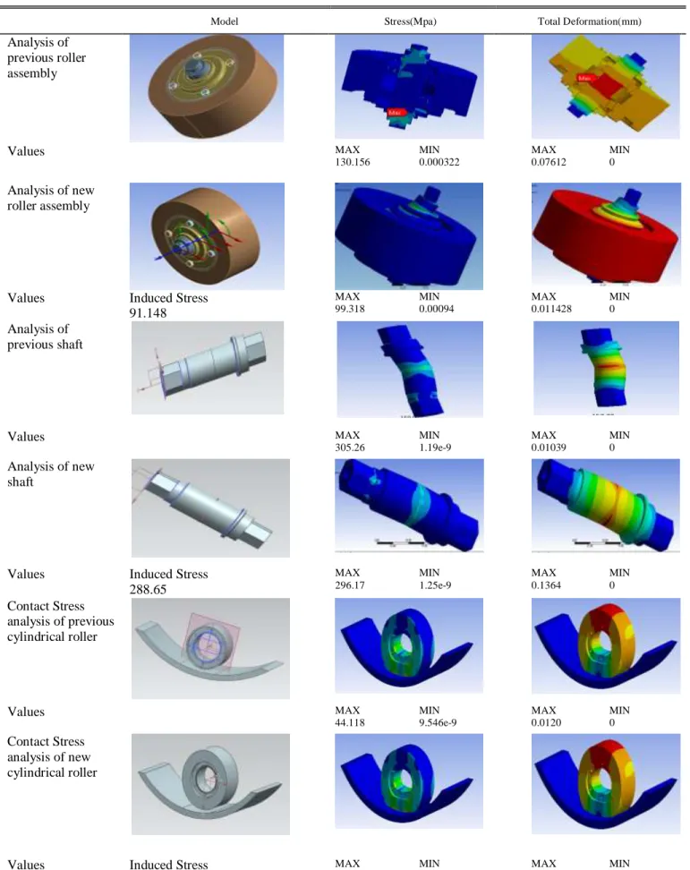
Analytical Design is verified with the help of ANSYS software. Exactly similar forces and constraints simulated in ANSYS to get accurate results. Von-mises stresses and Total deformation is calculated and compared for shaft, contact stresses in roller and total assembly.
Fig.2. TRB 30312 specifications
TABLEI
ANSYS ANALYSIS RESULTS
Model Stress(Mpa) Total Deformation(mm)
Analysis of previous roller assembly Values MAX 130.156 MIN 0.000322 MAX 0.07612 MIN 0 Analysis of new roller assembly
Values Induced Stress
91.148 MAX 99.318 MIN 0.00094 MAX 0.011428 MIN 0 Analysis of previous shaft Values MAX 305.26 MIN 1.19e-9 MAX 0.01039 MIN 0 Analysis of new shaft
Values Induced Stress
288.65 MAX 296.17 MIN 1.25e-9 MAX 0.1364 MIN 0 Contact Stress analysis of previous cylindrical roller Values MAX 44.118 MIN 9.546e-9 MAX 0.0120 MIN 0 Contact Stress analysis of new cylindrical roller
Values Induced Stress
41.1 MAX 45.68 MIN 9.146e-9 MAX 0.002247 MIN 0
2706 IV. EXPERIMENTAL RESULTS
A. Temperature Test
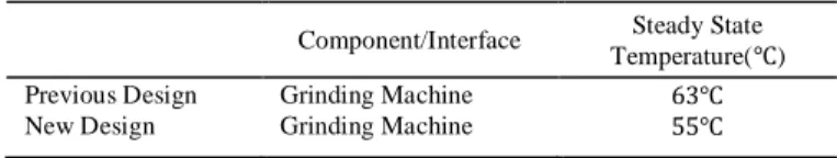
Fly ash is sticking to the inner race of roller cylinder due to rise in operating temperature of fly ash grinding. HTC infrared thermometer MT-4 is used to measure temperature. Improved design and reduction in unnecessary vibration leads to operating temperature reduction up to 8℃
B. Vibration Test
Bearing selected in previous design was not considered for operating temperature rise. Bearing expansion leads to misalignment of roller shaft inside bearing and this was the main cause of high amplitude vibrations.
Rion Vibration analyzer VA-12 with FFT analysis function was used to take vibration amplitude readings and FFT plots. Sample frequency 20 KHz used to draw FFT plots. Peak
amplitude of vibrations of fly ash grinding machine was0.8𝑚𝑚. After selection of proper bearings and redesigning shaft and roller reduced peak amplitude of machine up to
0.4𝑚𝑚.
C. Fly ash size
Sieve BS – 140 Mesh 300 used to measure fly ash size after grinding.[11] Final fly ash size of 50 micron achieved after grinding.
V. CONCLUSIONS
Bearing failure and high amplitude of vibrations due to lack of contact between inner race and roller shaft is detected. Redesigned the shaft as per bearing selection resulted into stress transfer and stress concentration minimization. Minimization of roller deformation in revised roller design gives added advantage to minimize vibrations. Vibrations and temperature rise are measured on site with the help of standard equipments. Vibrations and temperature rise reduced to acceptable limit. Testing of size of fly ash with standard sieve shows that design of roller is appropriate to grind fly ash up to 50 microns.
Future Scope: Higher capacity grinding machine can be designed and analyzed on the similar guidelines.
REFERENCES
[1] Mustafa Kemal Kaluci, research article on ,“Analysis of process parameters for a surface grinding process based on the Taguchi method”,Mersin University, Tarsus Technical Education Faculty, Department of Mechanical Education, 33140, Tarsus-Mersin, Turkey. [2] Thomas, A and Filippov, L.O., "Fractures, fractals and breakage energy
of mineral particles". International Journal of Mineral Processing, October 1999.
[3] Pranav Darji, “Evaluation of contact width for elastic hollow cylinder and flat contact through experimental technique and extending the capabilities of Hertz equation” IJSSER, 2013.
[4] Prabhakar Purushothaman, “Hertz Contact Stress Analysis and Validation Using Finite Element Analysis”,IJRASET, 2014.
[5] Iftekhar Ahmad and Prakash A. Mahanwar “Mechanical Properties of Fly Ash Filled High Density Polyethylene”, Mumbai University, India. [6] G. Marketos and M.D. Bolten, “Quantifying the extent of crushing in
granular materials: A probability-based predictive method”, Soil Mechanics Group, Engineering Department, University of Cambridge, UK.
[7] Ga´bor Mucsi, “Fast test method for the determination of the grindability of fine materials”, University of Miskolc, Institute of Raw Material Processing and Environment Process Engineering, 3515 Miskolc, Hungary.
[8] Nicolas Licane “Tutorial of Hertzian Contact Stress Analysis”, College of Optical Sciences, University of Arizona, Tucson, AZ USA 85721 [9] Vahid Monfared,“Contact stress analysis in rolling bodies by finite
element method statically”, Journal of Mechanical Engineering and automation 2012,2(2): 12-16.
[10] , R.S.Khurmi and J.K.Gupta, “A text book of Machine Design”, India, 2005,
[11] British Standard Sieve Series BS410-2:2000. [12] ASTM pipe selection standard SA106. TABLEII
OPERATING TEMPERATURE
Component/Interface Steady State Temperature(℃) Previous Design Grinding Machine 63℃ New Design Grinding Machine 55℃
Fig.4. Time and FFT plot of before designing grinding roller.