Review
1
Thermal stress relaxation and high-temperature
2
corrosion of Cr-Mo steel processed using
3
multifunction cavitation
4
Masataka Ijiri 1,*, Norihiro Okada 2, Syouta Kanetou 3, Masato Yamamoto 4, Daisuke Nakagawa 5,
5
Kumiko Tanaka 6 and Toshihiko Yoshimura 6
6
1-7 Sanyo- Onoda City University ; [email protected] 1, [email protected] 2, [email protected] 3,
7
[email protected] 4, [email protected] 5, [email protected] 6, [email protected] 7
8
* Correspondence: [email protected]; Tel.: +81-836-88-4562
9
10
Abstract: This research investigated high-temperature corrosion (500 °C) of Cr-Mo steel processed
11
using water jet peening or multifunction cavitation (MFC), and the suitability of such steel for
high-12
temperature boilers and reaction vessels. High-temperature corrosion was induced using an
13
embedment test and a coating test using sulfide-type K2SO4-Na2SO4 powder. To measure the
14
relaxation of the residual stress due to the decrease in work hardening caused by an increase in
15
specimen temperature and the difference in thermal shrinkage between the surface and interior of
16
the specimen, a thermal cycling test was conducted. For the MFC-processed specimen, the oxide
17
film that formed on the surface suppressed mass loss, prevented crack formation, and reduced the
18
compressive residual stress caused by high-temperature corrosion. MFC-processed Cr-Mo steel is
19
thus suitable for a high-temperature corrosion environment.
20
Keywords: water jet peening; multifunction cavitation; Hot corrosion; Thermal stress cycle; Cr-Mo
21
steel; embedding test; coating test;
22
23
1. Introduction
24
The importance of recycling has increased as waste disposal problems have become more
25
serious. The concept of thermal cycle recycling has attracted attention as it allows the heat generated
26
during incineration treatment to be recovered for power generation.
27
Highly efficient waste power generation is being actively promoted for the effective use of waste
28
energy. However, in the superheater in a high-efficiency waste incineration boiler, molten salt
29
containing chloride and sulfate forms in the ash attached to the gas side pipe surface due to the high
30
temperature of steam, causing high-temperature corrosion [1]. Further, when residual stress exists in
31
a bent or welded portion of a pipe, high-temperature corrosion and local corrosion due to molten salt
32
may be accelerated.
33
High-temperature and high-efficiency plants that utilize superheated steam (400 °C) have been
34
constructed. In high-temperature boilers (400 °C or higher), the risk of corrosion damage increases
35
significantly, and thus materials with high environmental resistance have been investigated. It is very
36
important to manufacture materials with such resistance or apply a surface modification that
37
provides it.
38
This present study focuses on water jet peening (WJP) technology, which utilizes cavitation. WJP
39
is applied as a preventive maintenance technology in nuclear power plants [2,3]. WJP reduces the
40
tensile residual stress in a structure, generated by welding or machining, to compressive residual
41
stress. This prevents cracking due to stress corrosion and metal fatigue. However, it has been reported
42
that the increase in pressure applied to Cr-Mo steel treated using WJP generates voids and cracks
43
inside the specimen [4].
44
The present authors recently developed multifunction cavitation (MFC) [4-7] processing
45
technology, which is a cavitation technique that applies ultrasonic waves to WJP. MFC can be used
46
like WJP to reform a material surface. Improvements in residual stress, strength, and corrosion
47
resistance have been reported for Ni-Cr-Mo steel [8], Cr-Mo steel [9,10], and Al alloy [11] processed
48
using MFC. It has been shown that the corrosion resistance of the surface of Cr-Mo steel and the
49
improvement in residual stress are affected by the period [12] and ultrasonic wave output [13] for
50
specimens processed with MFC.
51
The present study investigates sulfide-based high-temperature corrosion (500 °C) of WJP- or
52
MFC-treated Cr-Mo steel used for high-temperature boilers and reaction vessels.
53
2. Materials and Methods
54
2.1. Test material and processing conditions
55
The material used for the tests was Cr-Mo steel, which is a structural machine steel. Its chemical
56
composition is shown in Table 1. Rectangular specimens with dimensions of 100 × 100 × 3 mm3 were
57
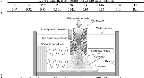
cut. Figure 1 shows the MFC processing equipment, in which an ultrasonic transducer
(WD-1200-58
28T, Honda Electronics Co., Ltd.) emits acoustic pulses towards the water jet as it emerges from the
59
nozzle. A swirl flow nozzle [14] is used at the tip of the WJP nozzle to increase the number and size
60
of cavitation bubbles. The swirl flow nozzle [11,14] suppresses the erosion marks that form in the
61
central part of a surface treated with WJP or MFC, and reduces surface damage due to cavitation
62
bubbles. The discharge pressure of the pump was about 35 MPa, the nozzle diameter was 0.8 mm,
63
and the distance between the nozzle and the specimen was assumed to be 65 mm. Processing was
64
performed in a tank (JIS-SUS310S) with dimensions of 41 × 44 × 60 cm3. In a previous study [12], the
65
effects of ultrasonic cycle conditions on the MFC-processed specimen surface were reported. It was
66
found that dual mode most improved corrosion resistance and residual stress; dual mode was thus
67
used in the present study. The output in this mode was 800 W and the frequency was varied from 25
68
to 27 kHz in steps of 10 Hz. The processing time was 2 min for all specimens.
69
70
Table 1. Chemical composition of Cr-Mo steel (mass%).
71
C Si Mn P Ni Cr Mo Cu Fe
0.37 0.32 0.81 0.014 0.012 0.95 0.15 0.14 Bal.
72
73
Figure 1. Equipment used for surface machining using WJP with ultrasonic waves.
74
2.2. High-temperature corrosion conditions
75
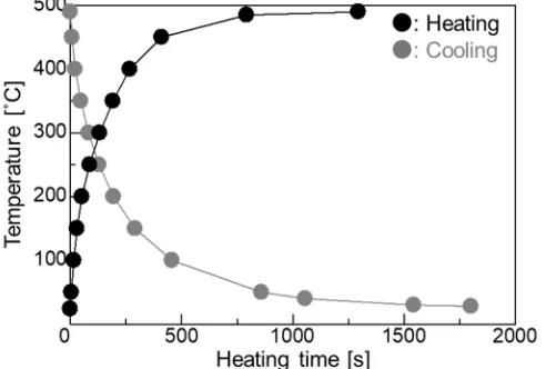
A thermocouple was welded to the specimen surface to determine the time at which the
76
specimen was inserted until its temperature reached 500 °C. The relationship between the specimen
78
surface temperature and the heat treatment time is shown in Fig. 2. This condition was adopted as
79
the condition for high-temperature corrosion since the temperature reached around 500 °C at about
80
7 min 50 s. To test corrosion, an embedding test and a coating test were adopted. A mixed ash of
81
K2SO4-Na2SO4 at a weight ratio of 1:1 was used. The melting point of this synthetic ash was above 870
82
°C, as determined from the corresponding phase diagram [15]. Using the embedding test, Cr-Mo steel
83
was placed at the bottom of an alumina crucible (height: 67 mm; outside diameter: 52 mm; capacity:
84
90 ml), covered with the synthetic ash, and heated in an electric furnace at 500 °C in the atmosphere.
85
After heating, the specimen was immersed in an aqueous solution of sodium hydroxide (18%),
86
potassium permanganate (3%), and pure water (79%) for 15 min to remove the oxide scale attached
87
to the specimen surface. The specimen was then immersed in an aqueous solution of diammonium
88
hydrogen citrate (10%) and pure water (90%) for 15 min. Finally, the specimen was cleaned with an
89
ultrasonic washer. In the coating test, 5 g of mixed ash and 20 ml of acetone were placed in a beaker
90
and stirred for 5 min with an ultrasonic washer. Then, about 1.26 g of the mixture was applied to the
91
specimen surface with a brush. The oxide scale was removed in the same way as done in the
92
embedding test. The coating test and embedding test were each repeated 20 times. After the corrosion
93
test, specimens were evaluated using mass loss measurements, optical microscopy (OM), and
94
scanning electron microscopy (SEM). For OM observation, each specimen was mirror-polished and
95
then corroded with 5 vol% nital.
96
97
Figure 2. Relationship between heating time and temperature.
98
2.3. Heat cycle conditions
99
Two kinds of stress are generated by heat treatment. The first is the thermal stress caused by the
100
difference in thermal shrinkage between the surface and interior of a specimen. The second is the
101
transformation stress that occurs when deformation is caused by the martensitic transformation due
102
to the temperature difference between the surface and interior of a specimen. In order to remove this
103
transformation stress, the time required for the specimen surface to cool to room temperature in the
104
atmosphere after heating was measured; it was found to be 25 min 43 s. 20 heating and cooling cycles
105
were performed. After each thermal stress cycle, residual stress measurement and OM observation
106
of a specimen section were carried out. Residual stress was measured using an X-ray stress analyzer
107
(MSF-3M, Rigaku Co., Ltd.) using the peak top method after measurement of the strain between (211)
108
lattice planes with the Cr Kα line generated at 30 kV and 10 mA. A region of 1 × 1 cm2 was measured.
109
Tensile residual stress was taken to be positive and compressive residual stress was taken to be
110
negative.
111
3. Results and discussion
113
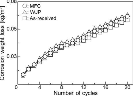
Figure 3 shows the relationship between corrosion loss and number of cycles in the embedding
114
test. Corrosion weight loss was small; it was smallest for the as-received specimen, followed by the
115
MFC-treated specimen and the WJP-treated specimen. OM observations (images not shown)
116
indicated no change in phase transformation or particle size after heat treatment.
117
118
Figure 3. Relationship between corrosion weight loss and number of cycles in embedding test.
119
120
Figure 4 shows cross-sectional SEM images of the as-received specimen after the embedding
121
test. Figure 4(a) shows that several cracks formed on the surface. These cracks occurred at the grain
122
boundaries. Cracks also formed near the surface. Figure 4(b) shows that voids formed at the grain
123
boundaries of ferrite inside the specimen. In addition to the effects of high-temperature corrosion,
124
the internal tension caused by the temperature difference between the surface and the interior
125
generated during heating due to the difference in thermal shrinkage caused the stress corrosion
126
cracking and voids. The cracks propagated mainly from grain boundaries. Grain boundary stress
127
corrosion cracking may have occurred.
128
129
Figure 4. Cross-sectional SEM image of as-received specimen (a) near the surface (broken line is the
130
specimen surface) and (b) away from the surface. Inset in (b) shows an enlarged SEM image of the
131
region indicated by the dashed box.
132
133
Figure 5 shows cross-sectional SEM images of a WJP-processed specimen after the embedding
134
test. Compared with Fig. 4, the cracks are narrower and do not branch. The cracks formed along the
135
grain boundaries of pearlite and ferrite. Grain boundary stress corrosion cracking may have occurred,
136
as in the as-received specimen. The WJP-processed specimen had fewer cracks at the surface
137
compared to the as-received specimen. Improvement in residual stress has been reported for
WJP-138
treated steel [9,10]. This compressive residual stress seems to suppress the thermal stress due to
high-139
temperature corrosion.
140
143
Figure 5. (a) Cross-sectional SEM images of a specimen after WJP treatment for 2 min. Enlarged SEM
144
images of the regions indicated by dashed boxes (b) A and (c) B in (a). The dashed lines indicate the
145
specimen surface.
146
147
Figure 6 shows cross-sectional SEM images of an MFC-processed specimen after the embedding
148
test. Although the width of the cracks is narrow, cracks on the surface did not propagate to the
149
interior, unlike in Fig. 5. A previous study [10] found that an oxide film forms on the surface when
150
the surface potential of Cr-Mo steel is increased by MFC. Improvement in residual stress [9] has been
151
reported for MFC-treated steel. The thermal stress due to high-temperature corrosion was alleviated
152
by the heat-insulating effect of the coating and the compressive residual stress on the surface. It is
153
assumed that the interior had no voids and cracks, and resisted the deformation caused by thermal
154
stress.
155
156
Figure 6. (a) Cross-sectional SEM image of a specimen after MFC treatment for 2 min. (b) Enlarged
157
SEM image of the region indicated by the dashed box in (b). The dashed line indicates the specimen
158
surface.
159
160
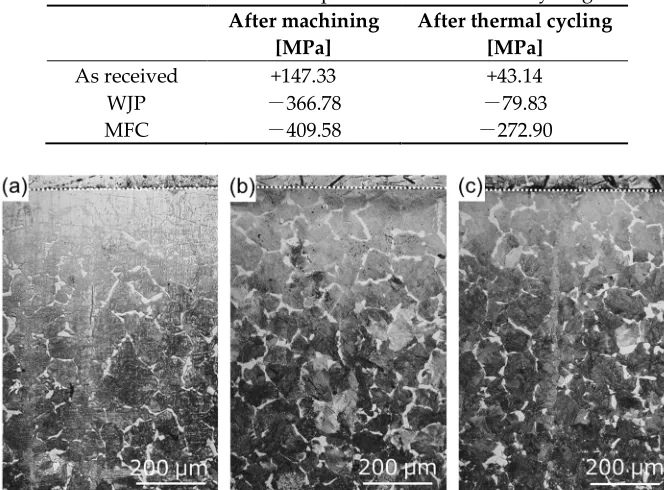
To measure the residual stress due to thermal stress, the as-received and treated specimens were
161
thermally cycled in an electric furnace at 500 °C under the atmosphere. The residual stress
162
measurement results are shown in Table 2. For the as-received specimen, tensile residual stress
163
decreased after heat treatment. For the WJP- and MFC-processed specimens, compressive residual
164
stress decreased after heat treatment; it decreased more for the WJP-processed specimen. In order to
165
clarify the cause of the stress decrease, cross-sectional OM images of the specimens are shown in Fig.
166
7. For all specimens, pearlite (black) changed to ferrite (white) near the surface. The OM observations
167
were conducted under the same illumination intensity for all specimens. Diffusion decarburization
168
likely occurred. The surface of the MFC-processed specimen had a thin decarburized layer. It has
169
formation of an oxide film [10]. Since this oxide film suppresses heat transfer from the surface to the
171
interior, it is considered that diffusion decarburization from the surface to the interior was less than
172
that in other specimens. When a decarburized layer forms near the surface, since thermal expansion
173
becomes larger than that for the normal part where thermal stress is low, the tensile stress increases
174
and cracks are likely to form. However, for all specimens, no cracking occurred on the surface after
175
thermal cycling. This is likely due to the low number of thermal cycles and the low temperature
176
applied to the surface. If either is increased, cracks will eventually form on the surface. It has been
177
reported that the high-temperature corrosion resistance improves when a dense oxide film exists on
178
a heat-resistant alloy surface [16]. For the MFC-processed Cr-Mo steel [10], an oxide film formed on
179
the surface, but iron oxide formed at a depth of 200 μm below the surface. In the embedding test, for
180
the MFC-process specimen, the cross section was corroded instead of the surface, so its corrosion
181
weight loss, shown in Fig. 3, is slightly less than that for the as-received specimen. A
high-182
temperature corrosion cycle was carried out in the coating test.
183
184
Table 2. Residual stress in specimens after thermal cycling.
185
After machining [MPa]
After thermal cycling [MPa]
As received +147.33 +43.14
WJP -366.78 -79.83
MFC -409.58 -272.90
186
187
Figure 7. Cross-sectional OM images of (a) as-received specimen and specimens treated with (b) WJP
188
and (c) MFC for 2 min after the thermal cycling test. The dashed lines indicate the surface of each
189
specimen.
190
191
Figure 8 shows the relationship between the corrosion loss and the number of cycles in the
192
coating test. The corrosion weight loss was small; the MFC-treated specimen had the smallest weight
193
loss, followed by the WJP has larger weight loss than as-received. The results for high-temperature
194
corrosion of the MFC-processed specimen for the coating test are different from those for the
195
embedding test.
196
Figure 9 shows cross-sectional OM images of the specimens after the coating test. Unlike the
as-197
received specimen, the treated specimens exhibited a microstructure mix of cementite and ferrite after
198
high-temperature corrosion. Cementite may have transformed into spheroidized cementite when
199
pearlite and ferrite were annealed at 500 °C; it eventually became spheroidized cementite if heating
200
was conducted for a long period. In the embedding test, it took time for the whole container to warm
201
up, and adhesion between the powder and the sample was poor; the mass reduction was thus small.
202
On the other hand, in the coating test, there was no container for the powder and the specimen
203
received heat directly in the electric furnace. It is thus considered that the surface cracked because the
204
206
Figure 8. Relationship between corrosion weight loss and number of cycles in the coating test.
207
208
209
Figure 9. Cross-sectional OM images of (a) as-received specimen and specimens treated with (b) WJP
210
and (c) MFC for 2 min after the coating test. The dashed lines indicate the surface of each specimen.
211
212
Enlarged images of the vicinity of the specimen surface are shown in Figure 10. For the
as-213
received specimen, large cracks did not occur in the vicinity of the surface, but the amount of
high-214
temperature corrosion was large. For the WJP-processed specimen, the corrosion amount was large,
215
as for the as-received specimen, and the density of surface cracks was the highest of all specimens.
216
For the MFC-processed specimen, the amount of high-temperature corrosion was small and the
217
density of surface cracks was low.
218
219
Figure 10. Enlarged cross-sectional OM images (a) as-received specimen and specimens treated with
220
(b) WJP and (c) MFC for 2 min after the coating test. The dashed lines indicate the surface of each
221
MFC-processed Cr-Mo steel is suitable for an environment with high-temperature corrosion
223
(e.g., a sulfide system) for the following reasons.
224
・The oxide film that forms on the specimen surface reduces the compressive residual stress and
225
decreased the heat transfer from the surface to the interior.
226
・Since voids and cracks are unlikely to form in the interior, cracks that can be generated by thermal
227
stress caused by high-temperature corrosion are unlikely to occur.
228
The results show that MFC treatment suppresses the high-temperature corrosion (500 °C) of
Cr-229
Mo steel in a sulfide system environment.
230
4. Conclusions
231
This study investigated sulfide-based high-temperature corrosion (500 °C) of WJP- and
MFC-232
processed Cr-Mo steel used for boilers and reaction vessels. In the embedding test, there was almost
233
no change in corrosion weight loss, but cracks formed in the as-received and processed specimens.
234
The cracks in the as-received and WJP-processed specimens propagated from the surface to the
235
interior, indicating grain boundary stress corrosion cracking. In the thermal cycling test, Residual
236
stress decreased in the as-received and processed specimens. The MFC-processed specimen exhibited
237
the least change in residual stress. Diffusion decarburization likely affected all specimen surfaces.
238
Compared with the WJP-processed specimen, an oxide film more easily formed on the
MFC-239
processed surface, so the thermal stress transmitted from the surface to the interior was low, and thus
240
the change in residual stress was small. In the coating test, the corrosion loss was smallest for the
241
MFC-treated specimen, followed by the as-received and WJP-treated specimens. This is related to the
242
oxide film that formed on the surface. The MFC-processed specimen was found to have the highest
243
high-temperature corrosion resistance.
244
Author Contributions: All authors made a substantial contribution to this research. M. I. (Masataka Ijiri)
245
conceived and designed experiments; M. I., N. O. (Norihiro Okada), S. K. (Syouta Kanetou), M. Y. (Masato
246
Yamamoto), D. K. (Daisuke Nakagawa), and K. T. (Kumiko Tanaka) carried out the experiments; M. I. and T. Y.
247
(Toshihiko Yoshimura) analyzed data; M. I. wrote the paper.
248
Funding: This research received no external funding.
249
Acknowledgments: This work was supported by the Innovative Science and Technology Initiative for Security
250
program of the Acquisition, Technology & Logistics Agency (ATLA) of Japan.
251
Conflicts of Interest: The authors declare no conflict of interest.
252
References
253
1. Y. Kawahara and M. Kira, Effect of physical properties of molten deposits on high temperature corrosion
254
of alloys in waste incineration environment, Zairyo-to-Kankyo, 46 (1997) 8-15.
255
2. N. Saitou, K. Enomoto, K. Kurosawa, R. Morinaka, E. Hayashi, T. Ishikawa, T. Yoshimura Development of
256
water jet peening technique for reactor internal components of nuclear power plant, J. Jet. Flow Eng, 20
257
(2003) 4-12.
258
3. K. Hirano, K. Enomoto, E. Hayashi and K. Kurosawa, Effects of water jet peening on corrosion resistance
259
and fatigue strength of type 304 stainless steel, J. Soc. Mat. Sci, 45 (1996) 740-745.
260
4. M. Ijiri, D. Shimonishi, D. Nakagawa and T. Yoshimura, Evolution of microstructure from the surface to
261
the interior of Cr-Mo steel by water jet peening, Mater. Sc. Appl, 8 (2017) 708-715.
262
5. T. Yoshimura, K. Tanaka, N. Yoshinaga, Development of mechanical-electrochemical cavitation
263
technology, J. Jet. Flow Eng, 32 (2016) 10-17.
264
6. T. Yoshimura, K. Tanaka and N. Yoshinaga, Nano-level material processing by multifunction cavitation,
265
Nanosci. Nanotechnol.-Asia. 8 (2018) 41-54.
266
7. T. Yoshimura, K. Tanaka and N. Yoshinaga, Material processing by mechanical-electrochemical cavitation,
267
BHR Group 2016 Water Jetting, (2016) 223-235.
268
8. M. Ijiri, D. Shimonishi, D. Nakagawa, K. Tanaka and T. Yoshimura, Surface Modification of Ni-Cr-Mo steel
269
9. M. Ijiri, T. Yoshimura, Evolution of surface to interior microstructure of SCM435 steel after
ultra-high-271
temperature and ultra-high-pressure cavitation processing, J. Mater. Process. Technol, 251 (2018) 160-167.
272
10. M. Ijiri, T. Yoshimura, Improvement of corrosion resistance of low-alloy steels by resurfacing using
273
multifunction cavitation in water, 2018 IOP Conf. Ser.: Mater. Sci. Eng, 307 (2018) 012040.
274
11. M. Ijiri, D. Shimonishi, D. Nakagawa and T. Yoshimura, Effect of water jet peening using ultrasonic waves
275
on pure Al and Al–Cu alloy surfaces, Int. J. Lightweight Mater. Manufac, (In press).
276
12. M. Ijiri, T. Yoshimura, Effect of ultrasonic irradiation conditions on metal surface during multifunction
277
cavitation, Mater. Sc. Appl, 9 (2018) 698-704.
278
13. M. Ijiri, T. Yoshimura, Sustainability of compressive residual stress on the processing time of water jet
279
peening using ultrasonic power, Heliyon, 4 (2018) e00747.
280
14. M. Ijiri, D. Shimonishi, D. Nakagawa and T. Yoshimura, New water jet cavitation technology to increase
281
number and size of cavitation bubbles and its effect on pure Al surface, Int. J. Lightweight Mater. Manufac,
282
1 (2018) 12-20.
283
15. L. P. Cook and H. F. McMurdie, Phase diagram for ceramists vol. Ⅶ, National institute of standards and
284
technology (National Bureau of Standards), p. 51 (Fig. 7018), The American Ceramic Soc. (1989).
285
16. K. Shimotori, K. Kawaguchi, M. Miyauchi and T. Tomita, Experiments on V2O5-Na2SO4 synthetic