Article
A Coupled Electro-Thermal Model for Simulating the
Lightning Strike Damage in Cfrps
Nikolaos Tselentis 1, Konstantinos Tserpes 2,*
1 Laboratory of Technology & Strength of Materials, Department of Mechanical Engineering & Aeronautics, University of Patras, Patras, 26500, Greece; [email protected]
2 Laboratory of Technology & Strength of Materials, Department of Mechanical Engineering & Aeronautics, University of Patras, Patras, 26500, Greece; [email protected]
* Correspondence: [email protected]
Abstract:
Lightning strike can cause a considerable damage in aircraft parts made from semiconducting materials such as Carbon Fiber Reinforced Plastics (CFRPs). Therefore, in recent years, the lightning strike phenomenon has attracted the interest of the academic community and the aircraft industry. Until now, the problem has been addressed mainly experimentally, while the reported numerical works are very limited. In the present work, a coupled electro-thermal FE model has been developed using the ANSYS commercial FE code to simulate the lightning strike damage in unidirectional CFRP laminates due to the Joule heat flux phenomenon. The model is based on the SOLID69 thermoelectric element and applies a non-linear, time-transient analysis. The main input to the model is the thermal-electrical properties of the composite material which vary with temperature. Using the model, a parametric study on the effect of mesh density and peak intensity on the thermal damage has been performed. Three electrical lightning strikes of low (10 kA), medium (30 kA) and high peak intensity (40 kA) have been applied according to the SAE ARP 5412 standard. The electro-thermal model has been validated against a numerical model from the literature. The numerical results reveal that the increase of peak intensity leads to the increase of the area and penetration depth of matrix thermal damage (pyrolysis) as well as to the increase of the area of fiber damage (deterioration and ablation). Through progressive damage modeling, the residual tensile strength of the CFRP plate after being subjected to lightning strike of different peak intensity has been predicted. Lightning strike initial damage has been simulated by translating the thermal field into degradation of elastic properties of the lamina. The results show an increase in the accumulated matrix damage and a decrease of tensile strength due to the initial lightning strike damage. For the maximum peak intensity of 40 kA, a decrease in tensile strength of 4.8% has been predicted.
Keywords: Lightning strike; CFRPs; Electro-thermal simulation; Progressive damage modeling; Finite element analysis
1. Introduction
Carbon fiber reinforced plastics (CFRPs) have evolved into the primary material of aircraft structures. A fundamental drawback of CFRPs is the non-conductive behavior of the resin matrix, which makes them vulnerable to lightning strikes. Lightning is a supersonic plasma wave of high pressure and temperature (approximate 30.000 K) that is distributed through a conductive air-path, transferring a large amount of electrical energy over a short period of time (microseconds). The aircraft are divided into three major lightning strike zones, which, according to SAE International ARP 5414 standard [1], encompass the structure-components that indicate the same possibility of lightning strike exposure. When a CFRP material is hit by a lightning strike, a complex damage
signifies a sequence of electro-thermal damage mechanisms of resin matrix burning, a resultant charred material, and a final carbon sublimation. From the above, it is obvious that a lightning strike is a complicated physical phenomenon which requires intense investigation.
Although lightning strike damage in CFRPs has been extensively investigated experimentally, to date, only a few numerical simulation models have been reported. Ogasawara et al. [3] introduced an electro-thermal FE model which predicts the thermal degradation field using the current waveforms experimentally tested by Hirano et al. [4]. The model did not include temperature-depended material properties. Wang et al. [5] presented a model based on a thermal deterioration method using varying – with temperature – properties except for electrical resistivity which was proved as a crucial study parameter. Additionally, a thermo-mechanical method was introduced, and the residual tensile strength of the various lightning strike imprints was evaluated. A remarkable work was presented from Abdelal et al. [6] that included a full temperature-dependent property-set with an extra copper lightning-protection system approach, but the model meshing-parameters were found to be poor. After the fiber sublimation a theory of superconductive properties was adopted through the thickness direction. Wang et al. [7] conducted a further lightning strike analysis with a local aluminum spraying coating, yet, without a considerable electrical conductivity alteration over temperature. Finally, Guo et al. [8] presented an electro-thermal study with varying-properties over temperature, that uses an adjusted model-meshing and a theory of isotropic material behavior after carbon ablation, which was treated as a gaseous state.
In the present work, a coupled electro-thermal finite element model was developed to simulate lightning strike damage in unidirectional CFRP laminates due to the Joule heat flux phenomenon. Using the model, a detailed parametric study was performed on the mesh density and the peak intensity on the different damage modes. The present model is the first step of an integrated model that will simulate all loading phenomena caused by a lightning strike.
2. Numerical model
2.1 Theoretical background
Lightning is considered as an instant high-energy electric current, whose electrical field in a conducting material is given by Maxwell’s equation of conservation of charge
∫ 𝐽 𝑛 𝑑𝑆
𝑆
= ∫ 𝑟𝑐 𝑑𝑉
𝑉
, (1)
where V represents any control volume whose surface is S, n is the outward normal to S, J is the electrical current density (current per unit area), and rc is the internal volumetric current source per unit volume. The electrical current flow is described by Ohm's law as
𝐽 = 𝜎𝛦𝛦, (2)
where σΕ is the electrical conductivity matrix, which could be isotropic, orthotropic, or fully
anisotropic and depends on temperature and on predefined field variables. E(x) is the electrical field intensity defined as
𝐸 = −𝜕𝜑
where 𝜑 is the electrical potential. Using this definition of the electrical field, Ohm's law is rewritten as
𝐽 = −𝜎𝛦𝜕𝜑
𝜕𝑥, (4)
Using Eqs. (1 – 4) the governing conservation of charge equation becomes
∫𝜕𝛿𝜑 𝜕𝑥 𝜎 𝛦𝜕𝜑 𝜕𝑥 𝑑𝑉 𝑉 = ∫ 𝛿𝜑 𝑟𝑐 𝑑𝑉 𝑉 + ∫ 𝛿𝜑 𝐽𝑑𝑆 𝑆 , (5)
The rate of electrical energy, Pec that is dissipated by a current flowing through a conductor, according to Joule's law is given as
𝑃𝑒𝑐= 𝐸 𝐽 = 𝐸 𝜎𝛦𝐸, (6)
The electrical energy is being converted, according to an energy conversion coefficient, ηv, to a respective amount of internal body heat, r, as shown in Eq. (7)
𝑟 = 𝜂𝜈 𝑃𝑒𝑐, (7)
Using the equations above, the heat conduction behavior could be described by the basic thermal energy balance relation, as
∫ 𝜌𝑈̇𝛿𝜃 𝑑𝑉 𝑉 + ∫𝜕𝛿𝜃 𝜕𝑥 𝑘 𝛿𝜃 𝜕𝑥 𝑑𝑉 𝑉 = ∫ 𝛿𝜃 𝑟 𝑑𝑉 𝑉 + ∫ 𝛿𝜃 𝑞𝑑𝑆 𝑆 , (8)
where V is a volume of solid material, with surface area S; ρ is the density of the material; U is the internal energy; k is the thermal conductivity matrix; q is the heat flux per unit area of the body, flowing into the body; and r is the heat generated within the body. Although electrical and thermal aspects of the problem are described from Eqs. (4) and (7), respectively, the physical coupling is derived from two main factors. Initially, conductivity is temperature-dependent on the electrical problem, and, secondly, the internal heat generation is a function of the electrical current in the thermal subject. As lightning strike induces thermal energy in the materials body, an amount of energy is lost in the boundary surfaces in the form of thermal radiation. A simplified version of the Stefan-Boltzmann Law [9] estimates the energy loss of a grey body, Qi, between a two-surface system, as it is given in Eq. (9)
𝑄𝑖= 𝜎 𝜀𝑖 𝐹𝑖𝑗 𝐴𝑖 (𝑇𝑖2+ 𝑇𝑗2)(𝑇𝑖+ 𝑇𝑗)(𝑇𝑖− 𝑇𝑗), (9)
where σ, is the Stefan-Boltzmann constant, εi is the effective emissivity, Fij is the surface radiation view factors, Ai is the area of surface i, ti and tj, is the absolute temperatures of surfaces i, j respectively. 2.2 Lightning current waveform
Figure 1. The lightning current waveform components [10]
Figure 2. A waveform of the lightning strike component
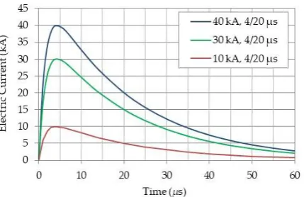
According to [10], the mathematical expression of the waveform shown in Figure 2 is given by
𝑖(𝑡) = 𝐼0(𝑒−𝛼𝑡− 𝑒−𝛽𝑡), (10)
where I0 is the peak value, α, β, are time reciprocal waveform characteristic values and t, is the time variable. The complete designation of the lightning waveform requires for another two main parameters, which are the action integral and the charge transfer. Action integral is defined as the integral of the square of the time-varying current over its time duration, Eq. (11). It is considered as a critical factor for the expansion of the damage, as it relates to the amount of energy deposited in the material, depending on its resistance. Charge transfer is the time integral of the current over its entire duration, Eq. (12), and refers to the total amount of the electrical charge that lightning contains.
𝐼 = ∫ 𝐼(𝑡)2 𝑡
0
𝑑𝑡, (11)
𝑄 = ∫ 𝐼(𝑡)0𝑡 𝑑𝑡, (12)
Figure 3. The modeled lightning current waveforms
2.3 Electro-thermal damage simulation
The lightning strike phenomenon induces the dissipation of electrical energy through a material’s body and, due to Joule heating, thermal damage occurs. Specifically, the CFRPs are considered to have orthotropic thermophysical properties. Through resistive heating, an electro-thermal coupling of a non-uniform temperature field is produced, resulting in an unequal thermo-chemical damage over materials volume. The key parameter for this detrimental spreading-manner is the different electrical resistivity of a unit volume [5], as the composite consists of a conductive and a dielectric component which is the carbon fiber and the resin matrix, respectively. While the temperature exceeds 300°C, resin decomposition begins and thermal stresses are developed [3]. Moreover, the temperature increment leads to the burning of the matrix and to a subsequent evaporation that leaves a pyrolyzed resin residue [4]. The state above could be found experimentally in the range of 400 – 500°C and, as the upper border is reached the accumulation of the pyrolysis trapped gases in the interlaminar area results in an abrupt explosion causing extensive delamination and matrix cracking. Furthermore, temperature greater than 500°C leaves a char material, in that the carbon act as the dominant component, due to the resin-mass reduction. Consequently, the thermophysical behavior perpendicular to the fibers direction advances to a more conductive state [6]. The temperature uprising causes the fiber’s chemical deterioration which is the main thermal-damage mechanism up to 3000°C [3]. At the temperature of 3000 °C, carbon begins to be sublimated and the 3316°C is considered as the critical breakage value, which provokes fiber ablation [5]. The mentioned critical value is the composite’s utmost temperature, as both of each ply components have been sublimated. The phenomenon is appeared to continue similarly in the layer below, that is now directly stroked. Experimental results have shown that ablation is followed by a ply-lifting area [4], oriented in the direction of the layer’s reinforcing material.
Figure 4. Flowchart of the electro-thermal model
The routine applies to the FE model the initial environmental conditions and defines the temperature ranges of 300 – 600 °C, 600 – 3000 °C and 3000 – 3316 °C, which correspond to the pyrolysis, the fiber deterioration, and the ablation fields, respectively. These ranges aim to represent crucial analysis checkpoints for material properties degradation. Time-step and step-size are considered as key parameters for the method implementation. A convergence study has been held and the time-step is defined in orders of magnitude of μs 10-1. Similarly, a large internal step-size
result in a non-robust analysis and a respective small size will include numerical rounding failures. A consequent convergence study has shown that step-size should vary between the magnitude of ns 10-1 and ns 102. In addition, a transient analysis has been applied due to the time-depended nature
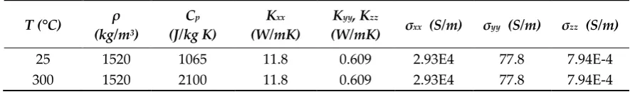
of the calculated values [9]. Through problem solution, the load is applied in a linearly interpolated manner for each time-step and the mean temperature is calculated for every element. If the value exceeds the undamaged temperature-region, the ablation state is checked firstly [8] and the material is treated as gas or a non-solid matter of a maximum electrical conductivity. On the contrary, if the calculated value lies among the boundary ranges, a further check is carried out, so that, if pyrolysis is found to exist, a weight reduction accompanied with electrical conductivity increment, perpendicular to fibers, should be introduced. Finally, if the fiber-deterioration state exists, the carbon properties are shown to govern the elements behavior. The temperature-dependent properties, according to Guo et al. [8], are given in Table 1, fulfilling properly the method requirements being discussed above.
Table 1. Temperature-dependent properties, which T denotes temperature, ρ denotes density, Cp denotes specific heat, Kxx, Kyy, Kzz denote thermal conductivity in the respective direction and σxx, σyy, σzz denote
electrical conductivity in the respective direction.
T (°C) ρ (kg/m3)
Cp
(J/kg K)
Kxx
(W/mK)
Kyy, Kzz
(W/mK) σxx (S/m) σyy (S/m) σzz (S/m)
25 1520 1065 11.8 0.609 2.93E4 77.8 7.94E-4
400 1520 2100 2.608 0.18 2.93E4 778 7.94
500 1100 2100 1.736 0.1 2.93E4 2E3 2E3
600 1100 1700 1.736 0.1 2.93E4 2E3 2E3
1000 1100 1900 1.736 0.1 2.93E4 2E3 2E3
3316 1100 2509 1.376 0.1 2.93E4 2E4 2E4
> 3316 1100 5875 1E8 1E8 1E8 1E8 1E8
2.4 Thermo-mechanical damage
The lightning damage field causes mechanical damage in the CFRP material which varies with depth, temperature and material direction. Wang et al. [5] have experimentally evaluated mechanical damage in terms of material property degradation. The results are summarized in Table 2. The data from the table has been used to simulate the initial lightning strike damage in the progressive damage model.
Table 2. Mechanical degraded properties according to induced thermal damaged fields [5]
Material Properties
Regions Temperature (°C)
Young‘s modulus
(GPa) Shear modulus (GPa)
X Y Z XY YZ XZ
1 25-260 137 8.2 8.2 4.36 3 4.36
2 260-600 82.2 4.92 4.92 2.616 1.8 2.616
3 600-3316 13.7 0.82 0.82 0.436 0.3 0.436
2.5 FE models
The CFRP plate is a IM600/133 laminate taken from [3] to enable comparison. The dimensions of the composite are 100 mm 150 mm; it consists of a unidirectional quasi-isotropic layup [45°/0°/-45°/90°]4s of 32 plies with a single-ply thickness of 0.125 mm, that equals to a 4 mm total thickness.
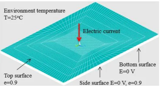
For the electro-thermal FE model, the plate was modeled using the 3D thermal-electric SOLID69 element [9]. The FE mesh, as shown in Figure 5, is constituted by two mesh regions, which are referred to the region of interest and the exterior area. This optimized mesh type was selected to reduce the total element number, in order to minimize the transient non-linear analysis solving-time and the computer-power used. The mesh was made full-parametrical and after a detailed study, the region of interest was assigned to a 1600 mm2 orthogonal area, which could fully include the lightning strike
imprint. The loading is applied on the top center node. At the bottom and the side surfaces, zero-voltage conditions are applied to simulate grounding. The environmental temperature is assumed to be 25°C and, due to thermal balance, a thermal radiation boundary condition of emissivity 0.9 is applied on the top and side surfaces. The mesh density has been be studied by means of a damage convergence study. To this end, four mesh cases of 21.000, 30.500, 46.500 and 89.800 elements which are referred as Mesh A, B, C, D, respectively, have been created.
Figure 5. FE mesh of the electro-thermal model and the applied boundary conditions
3. Numerical results
Using the electro-thermal FE model, a parametric study on the effects of mesh density and peak intensity has been performed in terms of the thermal damage developed in the CFRP plate by the lightning strike and the subsequent mechanical damage developed by the tensile load after the lightning strike.
3.1 Lightning strike simulation 3.1.1 Numerical model validation
In order to validate the electro-thermal FE model, a comparison with the similar model of [8] has been performed. For the comparison, the results obtained with Mesh D for the electrical current of 40 kA peak and the t1, t2 = 4/20 μs waveform characteristics have been used. The total in-plane damage area predicted by the two models deviate by 0.68%. This finding validates the present electro-thermal FE model.
3.1.2 Effect of mesh density on predicted damage
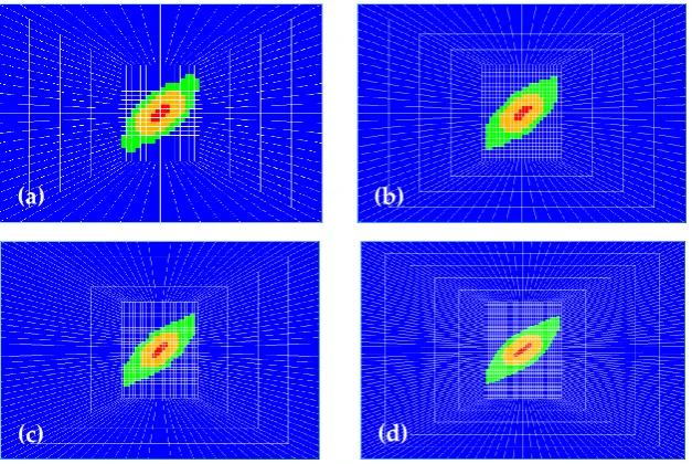
Figure 6 compares the predicted damage profiles for the four meshes A, B, C and D for the loading case of 40 kA peak and t1/t2 = 4/20 μs current waveform at 50 μs. The thermal damage profiles are divided into the pyrolysis, the fiber deterioration and the ablation areas depicted with green, orange and red colors, respectively. The developed detriment zones are encompassing one another with the pyrolysis to exist at the outer region and the fiber ablation at the inner region. Moreover, the damage pattern is shown to grow at the 45° direction following the orientation of the outer layer. Nevertheless, as the mesh-density increases, a high shape-differentiation is observed, with the degradation contour to appear smoother moving from mesh A to mesh D. The damage profile of mesh C matches better to mesh D rather than A. For a more detailed comparison, the profiles of in-plane damage have been quantified and plotted against time in Figure 7. The curves indicate that mesh A always predicts the highest damage area and mesh D the lowest.
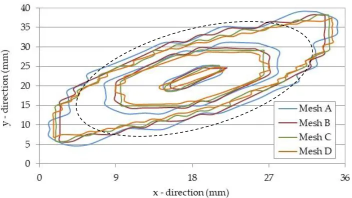
from which the internal of the oval shape represents an area that encompasses the lightning attachment point and the external of the oval shape represents the area induced by the fiber-direction damage spreading. Moreover, as the physics of the lightning damage phenomenon indicates a succession of the three damage types through the spatially temperature increment, the detriment mechanism of the oval’s internal surface is governed by all three damage phenomena in contrast to the mechanism of the oval’s external surface which relies entirely on the pyrolysis induced field. Therefore, the contours located in the interior surface are observed to converge, since the degradation is analyzed through all impairment regions and, so, the electro-thermal method can accurately simulate the accumulative thermal damage. On the contrary, the detriment of the exterior area deviates over the mesh-scenarios, as only the pyrolysis constituent of the electro-thermal method is used. As a result, the extended damage spreading at the edges of the damaged contour – governed by the fiber direction is highly-dependent on the single element surface and, so, as the mesh-density increases, the pyrolysis field presents a 5.7% maximum divergence. Through the overall study, the damage convergence is found to depend highly on the distance of the examined volume to the lightning attachment point. Thus, a converging status in the exterior area is feasible with an even greater than case D mesh-increment, yet, it is limited to the computer-power used and the subsequently required computer-solving time.
Figure 6. Predicted damage profiles for the four mesh cases: (a) mesh A, (b) mesh B, (c) mech C, and (d) mesh D. Green = pyrolysis, Orange = fiber deterioration, Red = fiber ablation
Figure 7. Total in-plane damage over time for meshes A-D
(a) (b)
(b)
(a)
(b)
(c)
Figure 8. Evolution of damage over time for the four mesh cases
Figure 9. Superimposing contour of the outer-layer lightning damage regions for mesh-cases A-D and an encircled area of excellent convergence
3.1.3 Effects of lightning strike load
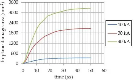
Figure 10 compares the predicted damage profiles for the loading scenarios of 10 kA, 30 kA and 40 kA (4/20 μs) computed using mesh C. The damage profiles are of the same shape. However, with increasing the peak intensity, there is a significant increase of damage area; from 340 mm2 at 10 kA
to 3240 mm2 at 40 kA. The damage profiles against time for each loading scenario are depicted in
Figure 11. According to Fig. 11, each detriment area is formed to a level of 85% of its final value, at the time of 20 μs.
To comprehend composite’s detriment pattern, a detailed study on the evolution of pyrolysis, fiber deterioration and ablation regions is addressed over time. The damage curves are depicted in the Figure 12. The produced pyrolysis and fiber degradation areas consist the 62% and the 36% of the total degradation field at the final time of 50 μsec, respectively. Moreover, the total thermal damage, the pyrolysis and the fiber deterioration surfaces are found to be interconnected by the estimated indexes of 6 and 1.5 for the respective 10, 30 kA and 30, 40 kA loadings cases. In contrast, the fiber ablation curves have an abrupt grow for all three scenarios, with a contribution to the total detriment of 1.6%. Furthermore, the evaluated indexes of 5 and 1.5 govern the ablation region for the 10, 30 kA and 30, 40 kA loadings, respectively.
Figure 10. Predicted damage profiles for the three load-cases: (a) 10 kA, (b) 30 kA, (c) 40 kA. Green = pyrolysis, Orange = fiber deterioration, Red = fiber ablation
Figure 11. Total in-plane damage over time for the three load-cases
(a)
(b)
(c)
Figure 12. Evolution of damage over time for the three load-cases
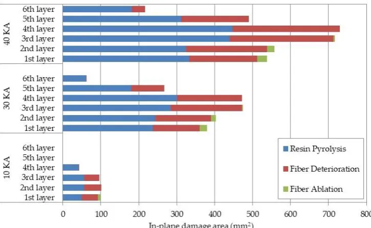
An additional result constitutes the through the thickness direction damage profiles, as they are shown in Figure 13. According to Fig. 13, for each scenario the layer of the lightning attachment point does not contain the maximum degradation field, as the most damaged plies are located underneath the extended ablation volume. While the lightning strike transfers a huge amount of thermal energy, the first stroked layers are evaluated to have an instant thermal failure and they are considered to ablate. The plies that locate directly below become the immediate energy receivers and the formed damage is governed by the pyrolysis and fiber deterioration regions. As a consequence, both third and fourth layers of the 30 kA and 40 kA scenarios, own an additional 24%, 35% of in-plane damaged surface to the first ply, respectively.
3.2 Axial tension
Subsequently to the lightning strike study, the effect of lightning strike damage on the tensile behavior of the CFRP laminate has been simulated using the progressive damage modeling (PDM) method [12-13]. In the PDM model, lightning strike initial damage has been simulated by translating the thermal field into degradation of mechanical properties using the data of Table 2 [5].
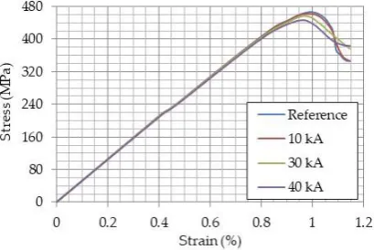
Figure 14 compares the predicted stress-strain curves for the reference plate (no lightning strike) and the plates stroked by lightning of three different peak intensities. The comparison shows a decrease in tensile strength and strain at failure due to the initial lightning damage. The decrease is larger for larger peak intensities. The values of tensile strength are listed in Table 3. The maximum predicted decrease of tensile strength and strain at failure for the 40 kA are 4.3% and 0.02%, respectively.
Figure 14. Tensile stress-strain curves for a reference, a low, a medium and a high lightning strike damaged case
Table 3. The tensile strength of the reference, the 10, 30 and 40 kA lightning strike damaged models Loading case Reference 10 kA damaged 30kA damaged 40 kA damaged
Tensile strength (MPa) 466.9 463.4 455.7 446.5
The damage profiles for the reference and the lightning strike damaged cases, at the laminate failure displacement are shown in Figure 15. In the lightning strike damaged cases a growing matrix failure differentiation is observed, that as the lightning imprint is increased, the local material discontinuities lead to an increasing altered stress field. The additional stresses contribute to a rising undamaged surface that is mainly located perpendicular to the carbon fibers direction, respectively. Moreover, the tensile failure modes are computed over displacement through the PDM analysis and they are presented in Figure 16. The degradation modes are categorized as fiber, matrix and delamination tensile failures.
The analysis is dominated by matrix failure, which, compared to the fiber and the delamination failures, is evaluated greater by one and two magnitudes of order, respectively. Moreover, the in-plane matrix damage is considered the same for all cases by the displacement of 1.4 mm, and after that, the cases of 30 kA and 40 kA demonstrate a detriment area deviation of 0.16 m2 to the reference
and the 10 kA cases, respectively. Furthermore, the fiber failure curves have a similar behavior with a damage deviation of 11.132 mm2 between the 30 kA, 40 kA and the reference and the 10 kA cases,
respectively. Finally, the 30, 40 kA cases are considered to lose their symmetrical stacking sequence and a subsequent curvature coupling along with the extensional one arises. This phenomenon leads to the development of a relatively small delamination failure area.
Figure 15. Predicted damage profiles due to tensile loading for the lightning damaged cases: (a) reference, (b) 10 kA, (c) 30 kA, (d) 40 kA. Green = matrix failure, Red = fiber failure, White = pyrolysis, Orange = fiber deterioration, Purple = fiber ablation
(a)
(b)
(c)
Figure 16. In-plane matrix, fiber and delamination tensile failures for a reference, a low, a medium and a high lightning strike damaged case
5. Conclusions
In the present work, a coupled electro-thermal finite element model was developed to simulate lightning strike damage in unidirectional CFRP laminates. A study of the effects of the mesh-density on the produced damage profile has been conducted and a subsequent study of a low, an intermediate and a high loading scenario has performed. Using the lightning strike imprints, a tensile loading simulation were subjected, that according to a PDM analysis estimates the residual tensile strength characteristics. From the numerical results obtained the following conclusions can be drawn: • The total damage, the fiber deterioration and the ablation fields through a mesh-density study show an excellent convergence over an area surrounding the lightning attachment point. A pyrolysis field divergence of 5.7% is estimated on the edges of the damaged contour.
• The time of 20 μsec is found to be a characteristic value, as the damage for all loading scenarios has been formed to a level of 85% of its final value, respectively.
• The layers located underneath the fiber ablation volume are observed to contain the maximum damage field, which is governed mainly by an extended pyrolysis area.
• For the 40 kA case the maximum tensile strength and strain decrease is observed as 4.3% and 0.02%, respectively.
• The damage by 30, 40 kA differentiate the overall stress field which contributes to an extra in-plane matrix tensile failure of 0.16 m2 compared to the reference and the 10 kA case.
Acknowledgment
The research leading to these results has received funding from the European Union Horizon 2020 Programme (H2020/2014-2020) under grant agreement n° 690638 (Project ECO-COMPASS: Ecological and Multifunctional Composites for Application in Aircraft Interior and Secondary Structures)
References
1. SAE International SAE_ARP_5414A. Aerosp. Recomm. Pract.2012.
2. Sonehara, T.; Kusano, H.; Tokuoka, N.; Hirano, Y. Visualization of lightning impulse current discharge on CFRP laminate. In 2014 International Conference on Lightning Protection, ICLP 2014; 2014.
3. Ogasawara, T.; Hirano, Y.; Yoshimura, A. Coupled thermal-electrical analysis for carbon fiber/epoxy composites exposed to simulated lightning current. Compos. Part A Appl. Sci. Manuf. 2010, doi:10.1016/j.compositesa.2010.04.001.
4. Hirano, Y.; Katsumata, S.; Iwahori, Y.; Todoroki, A. Artificial lightning testing on graphite/epoxy composite laminate. Compos. Part A Appl. Sci. Manuf.2010, doi:10.1016/j.compositesa.2010.06.008.
5. Wang, F. S.; Ding, N.; Liu, Z. Q.; Ji, Y. Y.; Yue, Z. F. Ablation damage characteristic and residual strength prediction of carbon fiber/epoxy composite suffered from lightning strike. Compos. Struct. 2014, doi:10.1016/j.compstruct.2014.06.029.
6. Abdelal, G.; Murphy, A. Nonlinear numerical modelling of lightning strike effect on composite panels with temperature dependent material properties. Compos. Struct.2014, doi:10.1016/j.compstruct.2013.11.007. 7. Wang, F. S.; Ji, Y. Y.; Yu, X. S.; Chen, H.; Yue, Z. F. Ablation damage assessment of aircraft carbon
fiber/epoxy composite and its protection structures suffered from lightning strike. Compos. Struct.2016, doi:10.1016/j.compstruct.2016.03.005.
8. Guo, Y.; Dong, Q.; Chen, J.; Yao, X.; Yi, X.; Jia, Y. Comparison between temperature and pyrolysis dependent models to evaluate the lightning strike damage of carbon fiber composite laminates. Compos. Part A Appl. Sci. Manuf.2017, doi:10.1016/j.compositesa.2017.02.022.
9. Kohnke, P. ANSYS Theory Reference - Release 5.6 1999, 1286.
![Figure 1. The lightning current waveform components [10]](https://thumb-us.123doks.com/thumbv2/123dok_us/8003694.1329696/4.595.210.387.319.441/figure-lightning-current-waveform-components.webp)
![Table 2. Mechanical degraded properties according to induced thermal damaged fields [5]](https://thumb-us.123doks.com/thumbv2/123dok_us/8003694.1329696/7.595.86.512.305.399/table-mechanical-degraded-properties-according-induced-thermal-damaged.webp)