Western University Western University
Scholarship@Western
Scholarship@Western
Electronic Thesis and Dissertation Repository
7-23-2014 12:00 AM
A CFD assisted control system design for supercritical water
A CFD assisted control system design for supercritical water
cooled reactor
cooled reactor
Rohit V. Maitri
The University of Western Ontario
Supervisor Prof. Chao Zhang
The University of Western Ontario Joint Supervisor Prof. Jin Jiang
The University of Western Ontario
Graduate Program in Mechanical and Materials Engineering
A thesis submitted in partial fulfillment of the requirements for the degree in Master of Engineering Science
© Rohit V. Maitri 2014
Follow this and additional works at: https://ir.lib.uwo.ca/etd
Part of the Controls and Control Theory Commons, and the Heat Transfer, Combustion Commons
Recommended Citation Recommended Citation
Maitri, Rohit V., "A CFD assisted control system design for supercritical water cooled reactor" (2014). Electronic Thesis and Dissertation Repository. 2169.
https://ir.lib.uwo.ca/etd/2169
This Dissertation/Thesis is brought to you for free and open access by Scholarship@Western. It has been accepted for inclusion in Electronic Thesis and Dissertation Repository by an authorized administrator of
WATER COOLED REACTOR
(Thesis format: Integrated Article)
by
Rohit Maitri
Graduate Program in Mechanical and Materials Engineering
A thesis submitted in partial fulfilment
of the requirements for the degree of
Masters of Engineering Science
The School of Graduate and Postdoctoral Studies
The University of Western Ontario
London, Ontario, Canada
Abstract
In this study, the methodology to construct a control system based on computational fluid
dy-namics (CFD) simulations is developed for supercritical water cooled reactor (SCWR). The
CFD model using Reynolds Stress Model (RSM) and k−ωS S T model is validated with the experimental cases of steady state and vertically up flowing supercritical water in circular tubes
for normal heat transfer and deteriorated heat transfer (DHT) cases. This model is extended to
simulate the transient thermal-hydraulic behaviour of supercritical fluid flow and heat transfer,
and the results are also compared with the 1-D numerical model, THRUST. The DHT
phe-nomenon is investigated using the turbulence kinetic energy (TKE) and velocity distribution
and their effect on the heat transfer. A correlation is reported between the TKE and
veloc-ity profiles and heat transfer phenomenon at supercritical condition. The non-dimensional
buoyancy and acceleration parameters are also used to predict the occurrence of DHT in the
supercritical water flow in circular tubes.
In the process of developing a control system for Canadian version of SCWR, system
iden-tification method is used to develop the linear dynamic models based on non-linear CFD
sim-ulations. Considering the strong cross-coupling between the inputs and outputs of the SCWR,
multiple input and multiple output (MIMO) system is decoupled and is converted to several
single input and single output (SISO) systems using pre-compensator. Based on the decoupled
SISO systems, loop compensator is developed for the control and stability of the reactor.
Keywords:Supercritical water cooled reactor (SCWR), Computational fluid dynamic (CFD),
THRUST, Deteriorated heat transfer, Buoyancy parameter, Acceleration parameter, Control
system, System identification, Decoupling, Linear dynamic model.
Chapters 3, 4 and 5 of this thesis will be submitted for publications.
All papers are drafted by Rohit Maitri and modified under the supervision of Prof. Chao
Zhang and Prof. Jin Jiang and in consultation with Dr. Dutta. The 1-D model THRUST
development work in chapters 3 and 4 has been carried out by Dr. Goutam Dutta from Prof.
Jin Jiang’s research group.
Acknowledgement
I would like to express my sincere gratitude to Prof. Chao Zhang and Prof. Jin Jiang for their
valuable guidance and support throughout my research work.
I would like thank to Dr. Goutam Dutta, a post-doctoral fellow in the Department of
Elec-trical and Computer Engineering at Western University and Associate Professor in the
Depart-ment of Mechanical Engineering IIITDM, Jabalpur, India, who provided valuable inputs to my
research work.
I would like to thank my lab-mates of the CFD laboratory at Western University who helped
me through long discussions on technical details of my research.
I would also like to thank my parents and my sister for their support and love during the
stressful period of this course.
Abstract . . . iii
Co-Authorship Statement . . . iv
Acknowledgement. . . v
Nomenclature . . . ix
Glossary . . . xi
List of Figures xii List of Tables xiv 1 Introduction 1 1.1 Overview . . . 1
1.2 Supercritical Fluids . . . 2
1.3 Supercritical Water Cooled Reactor (SCWR) . . . 4
1.4 Methodology . . . 6
1.5 Outline of the thesis . . . 8
References . . . 9
2 Literature Review 10 2.1 Flow Dynamics and Heat transfer studies of supercritical fluid flow . . . 10
2.1.1 Theoretical Background . . . 10
2.1.2 Experimental Studies . . . 11
2.1.3 Computational Studies . . . 15
2.2 Control System Studies . . . 17
2.3 Motivation . . . 18
References . . . 20
3 Validation of Numerical Models and Transient Simulations 25
Abstract . . . 25
3.1 Introduction . . . 31
3.2 Mathematical details of the numerical models . . . 33
3.2.1 GE of TH model . . . 33
Steady state solution methodology . . . 35
Heat transfer coefficient and friction factor . . . 35
Methodology to determine the local wall temperature . . . 36
Determination of critical heat flux for DHT . . . 37
3.2.2 Mathematical formulation of the CFD model . . . 38
3.3 Results and Discussions . . . 40
3.3.1 Validation of the numerical models at steady state condition . . . 40
3.3.2 Comparison of the numerical models at transient condition . . . 47
3.4 Conclusions . . . 53
References . . . 55
4 Numerical Analysis of DHT 59 Abstract . . . 59
4.1 Introduction . . . 65
4.2 Mathematical details of the numerical models . . . 68
4.2.1 Mathematical formulation of CFD model . . . 68
4.2.2 Mathematical formulations of the THRUST . . . 70
Solution methodology . . . 70
Heat transfer coefficient and friction factor . . . 71
4.2.3 Parameters to analyze DHT . . . 71
4.3 Results and Discussions . . . 73
4.3.1 Flow structure of supercritical water under various heat transfer condi-tions using CFD . . . 74
4.3.2 Analysis of DHT based on the acceleration parameters using THRUST. 78
No DHT in the experiment . . . 82
DHT in the experiment observed at a low mass flux condition. . . 82
DHT in the experiment at a high mass flux condition . . . 82
4.4 Conclusions . . . 86
References . . . 89
5 A CFD Assisted Control System Design Methodology 94 Abstract . . . 94
5.1 Introduction . . . 96
5.2 CFD method for CANDU SCWR simulations . . . 97
5.3 Development of a linear dynamic model . . . 99
5.4 Designing of a control system. . . 103
5.4.1 Design of a pre-compensator . . . 106
5.4.2 Design of a loop compensator . . . 107
Outlet Mass Flow Rate Control . . . 109
Outlet Temperature Control. . . 109
5.5 Conclusions . . . 110
References . . . 111
6 Conclusions and Future Work 112 6.1 Conclusions . . . 113
6.2 Future work . . . 115
Curriculum Vitae 117
Nomenclature
symbols
Cp Specific heat capacity
E Eckert Number, (Tpc−Tb)/(Tw−Tb)
g Gravitational acceleration
k Turbulence kinetic energy
P Pressure
Pr Prandtl number
T Temperature
Subscripts
b,∞ Bulk
cr Value at critical point
pc Pseudo-critical
w Wall
Greek Letters
Energy dissipation
λ Thermal conductivity
µ Dynamic viscosity
ρ Density of a fluid
ω Specific energy dissipation
BWR Boiling Water Reactor
CFD Computational Fluid Dynamics
DNS Direct numerical Simulations
GIF Generation IV Forum
HTD Heat Transfer Deterioration
LES Large Eddy Simulation
MIMO Multiple Input and Multiple Output
PCL Pseudo-critical Line
PCP Pseudo-critical Point
PCR Pseudo-critical Region
PDE Partial Differential Equations
PWR Pressurized Water Reactor
RANS Reynolds Averaged Navier-Stokes
R & D Research and Development
RSM Reynolds Stress Model
SCFPP Supercritical Fossil Power Plant
SCFR Supercritical Fast Reactor
SCWR Supercritical Water Cooled Reactor
SISO Single Input and Single Output
SST Shear Stress Transport
TKE Turbulence Kinetic Energy
Glossary
• Critical point - is the point where the distinction between the liquid and gas phases disappears, i.e. both phases have the same temperature, pressure and volume. This point
is characterized by theTcr, Pcr, Vcr which have unique values for each pure substance.
• Supercritical fluidis a fluid at pressures and temperature that are higher than the critical pressure and critical temperature.
• Pseudo-critical point(PCP) is a point at a pressure and temperature above the critical values corresponding to the maximum value of the specific heat for this particular
pres-sure.
• Normal heat transfercan be characterized in general with wall heat transfer coefficients similar to those of subcritical convective heat tranfer far from the critical or
pseudo-critical regions, when are calculated according to the conventional single-phase
Dittus-Boelter type correlations.
• Deteriorated heat transfer is characterized by lower values of the wall heat transfer coefficient compared to those at normal heat transfer; and hence has higher values of
wall temperature within some part of a test section or within entire test section.
• Improved heat transferis characterized by higher values of the wall; heat transfer co-efficient compared to those at the normal heat transfer; and hence lower values of wall
temperature within some part of a test section or within the entire test section.
• Near-critical point is actually a narrow region around the critical point where all the thermo-physical properties of a pure fluid exhibit rapid variations.
• Pseudo-film boilingis a physical phenomenon similar to subcritical pressure film boil-ing, which may appear at supercritical pressures. At pseudo-film boilboil-ing, a low density
fluid at temperatures above the pseudo-critical temperature prevents a high-density fluid
from contacting(“rewetting”) a heated surface. Pseudo-film boiling leads to the
deterio-rated heat transfer region.
1.1 Overview of development of nuclear reactors1 . . . . 2
1.2 Phase diagram of water5 . . . . 4
1.3 Variation of properties of water near pseudo-critical point4 . . . . 5
1.4 Layout of Supercritical Water Cooled Reactor (SCWR) . . . 6
1.5 Methodology for control system design of SCWR . . . 7
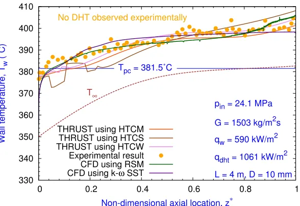
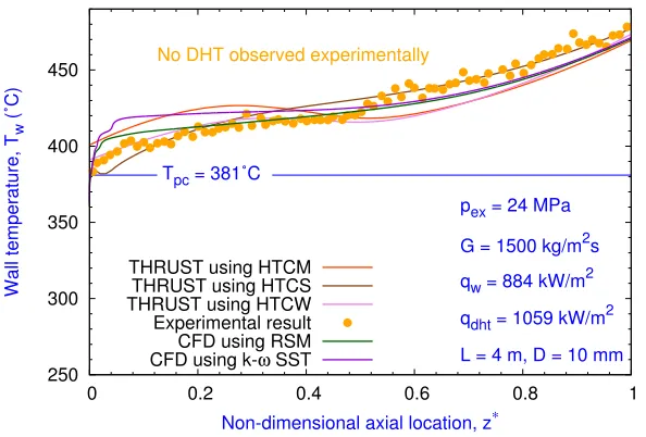
3.1 Comparison of the heat transfer coefficient by THRUST with the experimental data26for Case 1. . . 41
3.2 Comparison of the wall temperatures with the experimental data26 for Case 1. . 41
3.3 Comparison of the wall temperatures with the experimental data29 for Case 2. . 42
3.4 Comparison of the wall temperatures with the experimental data26 for Case 3. . 43
3.5 Comparison of the wall temperatures with the experimental data26 for Case 4. . 43
3.6 Comparison of the wall temperatures with the experimental data26 for Case 5. . 44
3.7 Comparison of the wall temperatures with the experimental data29 for Case 6. . 45
3.8 Comparison of the wall temperatures with the experimental data26 for Case 7. . 46
3.9 Step decrease in the inlet mass flow rate by 20% for Case 3 . . . 49
3.10 Step increase in the wall heat flux by 10% for Case 3 . . . 50
3.11 Sinusoidal variation of the inlet mass flow rate for Case 3 . . . 51
4.1 Results using CFD for Case 1 . . . 75
4.2 Results using CFD for Case 2a . . . 76
4.3 Results using CFD for Case 3 . . . 79
4.4 Results using THRUST for Case 1 . . . 81
4.5 Results using THRUST for Case 2a. . . 83
4.6 Results using THRUST for Case 2b . . . 84
4.7 Results using THRUST for Case 3 . . . 85
5.1 CANDU SCWR Fuel7channel . . . 98
5.2 Dynamic model for the CANDU SCWR . . . 100
5.3 Transient response to the step decrease in the inlet mass flow rate by 10% . . . 101
5.4 Transient response to the step increase in the heat flux rate by 10% . . . 102
5.5 Linear dynamic model validation with the CFD results with the step change in
the inlet mass flow rate . . . 103
5.6 Linear dynamic model validation with the CFD results with the step change in
the input heat flux . . . 104
5.7 Block diagram of the control system for the CANDU SCWR . . . 105
5.8 The distribution ofdj(w) for different columns of original and pre-compensated
plant . . . 108
2.1 Parameters corresponding to Heat Transfer correlations . . . 14
3.1 Parameters corresponding to HTC correlations . . . 37
3.2 Geometrical and operating parameters of the experiments under consideration . 40
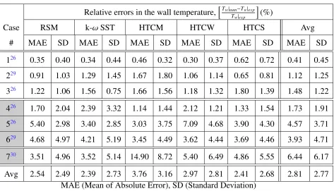
3.3 Relative errors between the numerical and experimental results for the wall
temperature . . . 46
3.4 Relative difference obtained by CFD and THRUST for the wall temperature (%) 52
4.1 Geometrical and operating parameters of experiments . . . 74
4.2 Prediction of DHT on the basis of buoyancy parameters . . . 80
5.1 Specifications of the CANDU-SCWR6, 7 . . . 98
Chapter 1
Introduction
1.1
Overview
The global demand for energy keeps on increasing each year. Considering the
environmen-tal concerns and depletion of fossil fuels, the use of alternate energy sources is important for
the future of mankind. Among these energy sources, the nuclear energy is one of the major
alternatives and it is being investigated widely to make nuclear reactors reliable, safe and
eco-nomically viable for electricity generation.
The first generation of nuclear reactors was developed in the 1950s and 60s as a prototype
reactors. In the next decade, the second generation reactors began as a commercial power
plants. With the number of modifications and evolutionary designs, Generation III reactors
were developed in 1990s. Currently, the advances to Generation III reactors are under
de-velopment and the new plants to be built till 2030 will be chosen from the Generation III+
reactor concepts. At every stage, the next generation reactors are designed with the aim of
higher safety and better economics. The research community has continuously explored the
innovative advances to existing reactors and hence R&D for Generation IV reactors which are
planned to be in operation after 2030 has stimulated worldwide interest in the researchers. The
timeline of the different nuclear designs is shown in Fig.1.1.
The Generation IV forum (GIF) has investigated different designs and finalised on the
Figure 1.1: Overview of development of nuclear reactors1
lowing six reactor concepts as Generation IV reactors :
1. Gas-Cooled Fast Reactor (GFR)
2. Lead-Cooled Fast Reactor (LFR)
3. Molten Salt Reactor (MSR)
4. Sodium-Cooled Fast Reactor (SFR)
5. Supercritical-Water-Cooled Reactor (SCWR)
6. Very-High Temperature Reactor (VHTR)
Among the above-mentioned reactors, the SCWR is the only reactor which uses water as
a coolant. The SCWR uses the water at supercritical pressures whereas all the previous water
cooled reactors used water at subcritical pressures. The use of water at supercritical pressures
in nuclear reactors is new and it will be investigated in this study.
1.2
Supercritical Fluids
1.2. SupercriticalFluids 3
is above its critical point. Supercritical fluids have been of interest for industry due to its
vari-ous applications. Supercritical fluids have been used to increase the efficiency of fossil power
plants, as a fuel in chemical and nuclear rockets, as a coolant for power transmission
equip-ments, as a refrigerant in air-conditioning and refrigerating systems, as a coolant and fuel for
supersonic transport, for transforming geothermal energy into electricity, for processes such
as supercritical fluid extraction, supercritical fluid chromatography and polymer processing in
chemical and pharmaceutical industries.2
It is important to note that the term “supercritical fluid” is not used to identify some
spe-cific class of fluids but it is used as an indication of the thermodynamic state of the fluid. At
supercritical condition, the temperature and pressure of the fluid is greater than Tcr and Pcr,
respectively. The unique feature of a fluid at supercritical condition is the absence of phase
boundaries. As it can be observed from the phase diagram (Figure1.2) that there does not exist
any phase boundary (solid line) at supercritical condition and it is a single phase fluid. The
critical temperature and pressure for water is 647 K and 22.1 MPa and forCO2is 304.21 K and
7.3825 MPa, respectively.3,4
It is observed that, at a critical point, water has maximum specific heat.4 The point where
the specific heat is maximum for a given supercritical pressure is characterized as
pseudo-critical point (PCP) and the line joining these points is called as pseudo-pseudo-critical line (PCL)
(Fig. 1.2). When compressed water (P> Pcr) is heated to temperature higher than the critical
temperature, a transition from liquid like substance to vapour like substance is observed.4
Al-though this transition is continuous, the thermo-physical properties of water vary significantly
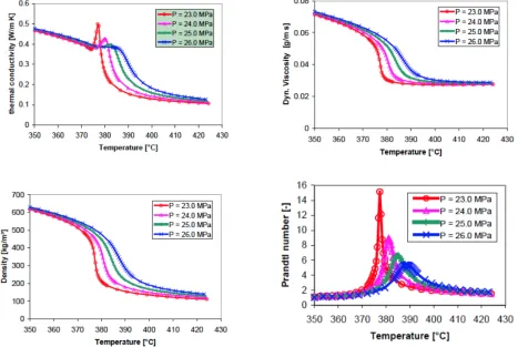
near PCL.4Fig. 1.3shows the variation of some of the thermophysical properties of
supercrit-ical water near PCP.
Near PCP, the density, thermal conductivity and dynamic viscosity decrease and become
constant after that. The same trend is observed for kinematic viscosity except that it regains its
values as we increase the temperature. The sharp peak is observed at PCP for Prandtl number,
Figure 1.2: Phase diagram of water5
1.3
Supercritical Water Cooled Reactor (SCWR)
Although nuclear reactors with supercritical water have never been in operation, supercritical
water has been used in the commercial fossil power plants already. The advantage of improved
thermal efficiency of supercritical water in fossil power plants over subcritical water was
deci-sive factor to operate Supercritical Fossil Power Plants (SCFPP). In steam power plants (where
water at subcritical condition is used), water is converted to steam by heating and then it is
passed to turbines for power generation. The major problem faced with these power plants is
the ‘boiling crisis’ which is often referred as ‘dryout’ also. While phase change occurs
dur-ing the heatdur-ing of water, bubble formation is observed near metal surface which decreases the
efficiency of heat transfer, thus causes localized overheating of heating surface.2,3 But in
1.3. SupercriticalWaterCooledReactor(SCWR) 5
Figure 1.3: Variation of properties of water near pseudo-critical point4
there is no ‘dryout’ problem and hence the problem of overheating is avoided. Higher enthalpy
of the supercritical water makes it an effective coolant as it needs lower mass flow rate per
unit core thermal power. This results in the reduction in the size of pumps, piping, associated
equipments and pumping power as well. As the supercritical condition ensures single phase
flow dynamics, the needs for steam separators, recirculation pumps and steam generators are
also eliminated.1 Moreover, the most important advantage is the improved thermal efficiency
of the SCWR (around 44%) compared to the existing LWRs (33-35%).
Higher efficiency, single phase flow, higher enthalpy, smooth transition at PCL are the
advantages for use of supercritical water in power plants. Along with these advantages,
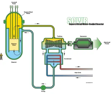
Figure 1.4: Layout of Supercritical Water Cooled Reactor (SCWR)
Although the supercritical fluid shows higher enthalpy (as an advantage), it also has sharp
decrease in density (as a disadvantage). This density behaviour produces prominent buoyancy
effects and sharp increase in thermal expansion coefficient results in large acceleration effects.
These two effects combined with the large property changes near PCL cause decrease in the
heat transfer coefficient. This phenomenon is referred as heat transfer deterioration(HTD)
which results in an increase in the wall temperature.
1.4
Methodology
The nuclear reactors are generally operated at given operating conditions. Hence, the
pertur-bation in the inputs affects the outputs and consequently the operating conditions. Hence, it is
1.4. Methodology 7
The governing equations for the fluid flow and heat transfer in a SCWR are non-linear
par-tial differential equations (PDEs) and it is difficult to directly establish the dynamic relationship
between the inputs and outputs, so, the white box method could not be used. Hence, for the
non-linear systems like SCWRs, the black box method is useful for designing a control system.
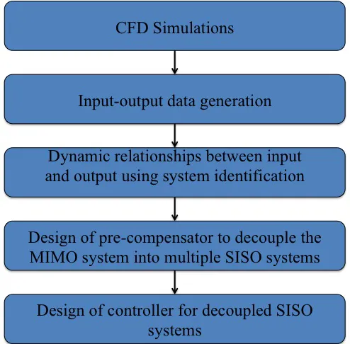
The black box method requires the input and output data for finding a dynamic relationships
between them. For generating the input-output data, computational fluid dynamics (CFD)
sim-ulations are used in this study. Before proceeding for the CFD simsim-ulations for SCWR where
supercritical water flows through fuel rods, the validation of CFD model is important.
How-ever, in the literature, no experimental results are available for the supercritical fluid flow in rod
bundles. Therefore, the current CFD model is validated for the flow in circular tubes for which
there are numerous experimental results. Next, the supercritical water flow through reactor
core is approximated to the fluid flow in circular tubes by keeping the heat flux to mass flux
ratio same and using the equivalent hydraulic diameter. The methodology used for designing a
control system based on CFD simulations is shown in Fig. 1.5.
1.5
Outline of the thesis
The remaining thesis material is organized as follows :
In Chapter 2, a literature review of the thermal-hydraulic analysis and control system
stud-ies of supercritical fluid flow is presented. Chapter 3 consists of the comparison of steady state
numerical results with the experimental data and the extension of the presented numerical
mod-els to simulate transient thermal-hydraulic behaviour for supercritical fluid flows. In Chapter 4,
the detailed analysis of different modes for the heat transfer in supercritical fluids is performed
by analysing the turbulence kinetic energy and velocity profiles, and various dimensionless
parameters under broad range of operating conditions. Chapter 5 presents the methodology of
control system design for supercritical water cooled reactor (SCWR) based on CFD results.
References 9
References
[1] US DOE, NERAC, and GIF. A Technology Roadmap for Generation IV Nuclear Energy
Systems. Technical report, 2002.
[2] IL Pioro, HF Khartabil, and RB Duffey. Heat transfer to supercritical fluids flowing in
channels, empirical correlations (survey). Nuclear Engineering and Design, 230(1-3):69– 91, 2004.
[3] JY Yoo. The Turbulent Flows of Supercritical Fluids with Heat Transfer. Annual Review of Fluid Mechanics, 45:495–525, January 2013.
[4] X Cheng and T Schulenberg. Heat Transfer at Supercritical Pressures: Literature Review
and Application to an HPLWR. Scientific report FZKA6609, Forschungszentrum Karl-sruhe, 2001.
[5] S Mokry, I Pioro, A Farah, K King, S Gupta, Wa Peiman, and P Kirillov. Development of
Literature Review
2.1
Flow Dynamics and Heat transfer studies of
supercriti-cal fluid flow
The detailed literature review of heat transfer and fluid flow mechanism at supercritical
condi-tion is presented in this seccondi-tion. The study of heat transfer for supercritical fluids needs the in
depth understanding of flow characteristics near supercritical condition. Thus, this section will
consist of discussions on fluid flow structures in order to explain the heat transfer phenomenon.
2.1.1
Theoretical Background
It is indeed very important to discuss the two major effects differentiating fluids at the
super-critical condition from the subsuper-critical condition. These two effects besides property variation
are the enhanced buoyancy effect and acceleration effect. The enhanced buoyancy effects are
the result of the decrease in the density near the PCP whereas acceleration effect results from
the increase in the thermal expansion coefficient. The acceleration effect can also be explained
using mass conservation principle. When a constant heat is provided to a fluid, density of the
fluid decreases near the PCP and to conserve the mass, the decreased density will cause an
in-crease in the velocity, accelerating the flow. The buoyancy effect acts always in the direction of
gravitational force, irrespective of the flow direction whereas acceleration effect always acts in
2.1. FlowDynamics andHeat transfer studies of supercritical fluid flow 11
the direction of a flow irrespective of the gravitational force. Although these two effects are
re-sult of large property variation, researchers investigated these effects extensively because large
changes in the density and thermal expansion coefficient affect the heat transfer phenomenon
more than other properties do.
As discussed in the previous chapter, supercritical water shows abrupt changes in the
ther-mophysical properties near the PCP. The peak inCpnear the PCP is one of the main reasons for
the selection of supercritical water as a coolant in Gen IV nuclear reactor. Moreover, there is
no boiling crisis in supercritical water which avoids severe deterioration in heat transfer (DHT)
due to dryout. However, supercritical water shows sharp decrease in density near PCP causing
DHT.
Hall et al.1 explained the dominant cause of DHT as the modification of shear-stress
dis-tribution in the flow domain which in turn affects the turbulence production. In the similar
direction, Tanaka et al.2 developed an approximate analytical equations to predict the velocity
and temperature profiles when both the acceleration and buoyancy effects are predominant. It
was found that for low mass flux conditions when certain heat flux conditions are satisfied,
the shear stress continues to decrease in the near wall region and achieves a negative value.
As the consequence of the change in shear stress distribution, the velocity profile changes to
"M-shaped" velocity profile indicating peaks in velocity in the near wall region.
2.1.2
Experimental Studies
The two major objectives for the experimental studies in supercritical fluids are, (1) to study
the fluid flow and heat transfer mechanism and (2) to develop heat transfer correlations at
su-percritical conditions.
Although boiling crisis is avoided in supercritical water, strong variation in thermo-physical
temper-ature approached the PCP was first observed by Bishop et al.3 and similar observations were
also made by others.4–6 One of the possible reasons for this behaviour was given as unstable
characteristics of the thin boundary layer formed because of abrupt thermophysical property
changes. The alternate reason for this behaviour was suggested as the pseudoboiling which is
similar to boiling in subcritical fluids. However, Shiralkar et al.7 and Swenson et al.8
com-mented that pseudoboiling theory does not hold for the supercritical fluids. Moreover, Hall
et al.9 also concluded that the bubble formation might have caused due to the impurities and
not the pseudoboiling. The common consensus among researchers on the satisfactory reason
for the instability at supercritical pressures is still not achieved and this subject needs further
investigation.10
The theoretical assumption of the effect of the buoyancy on the heat transfer mechanism
in the supercritical fluids became more acceptable when the results for the upward and
down-ward flows were compared.1,2 While the deteriorated heat transfer was major concern in the
supercritical fluids, Yamagata el al.11 found that in low heat flux conditions, the heat transfer
coefficient increases significantly near the PCP. However, the peak in the heat transfer coeffi
-cient was found to decrease with the increase in the heat flux.12 It was also reported that in
upward flows, buoyancy effect can cause deterioration or enhancement in the heat transfer but
in the downward flows only heat transfer enhancement is observed. However, the deterioration
due to the acceleration effect can be observed in upward flows as well as downward flows.13
The fundamental reason for the buoyancy effect was given as the density variation in the radial
direction whereas for the acceleration effect, it is the axial variation in density.10
The experiments are also carried out since 1970s to generate the wall temperature data for
the validation of numerical models.11,14–16 The validation of numerical models requires the
experimental data in broad range of operating conditions of pressure, temperature, heat flux
and mass flux. Hence, the experiments are still being carried out with the modern experimental
equipments and techniques.17,18 There were also a few experiments performed to find the flow
2.1. FlowDynamics andHeat transfer studies of supercritical fluid flow 13
Kurganov et al.19 performed an experiment for the supercriticalCO2flow in vertical
circu-lar tubes to study heat transfer, and velocity and temperature fields in deteriorated heat transfer
condition. It was found that the deterioration is observed only in the upward flows and in
the deteriorated heat transfer zone, structural changes in velocity (M-shaped profile) and shear
stresses (negative values) are observed due to buoyancy and acceleration effects. Hence, these
changes contribute to lower values of eddy viscosity (suppression in turbulence) in the fluid
layer causing the deterioration in heat transfer.
The first approach to document the mean velocity and temperature profiles for upward
turbulent air flow in uniformly heated circular tube was taken by Shehata et al.17 The
experi-mental results obtained were used later to validate the DNS code by Bae et al.12 Researchers
have also been performing experiments to gather thermal-hydraulic data for supercritical fluids
in geometries other than circular tubes. Experiments were performed by Wardana et al.20 for
air flow in annulus with strongly heated inner cylinder, Kang et al.21 for liquid R-113 flow in
vertical annular channel and by Licht et al.22 for water flow in square annular channels.
The researchers have been trying to formulate the heat transfer correlations for supercritical
fluids because the well known Dittus-Boelter correlation fails in the PCR. There are umpteen
number of correlations in literature, but there are still discrepancies in the results using them
for broad range of operating conditions. The single correlation to cover both the normal and
deteriorated heat transfer is still awaited.23 Pioro et al.24 and Yoo13 did an extensive literature
survey on the research work in this direction and presented correlations developed by diff
er-ent researchers. The majority of those correlations are of Dittus-Boelter type which can be
expressed by Equation2.1.
Nu=CRen1
θ Pr
n2
θ F (2.1)
where,
F = Pr∞
n3 ρw
ρ∞ !n4 µ
w
µ∞ !n5 λ
w
λ∞ !n6
cp
cp∞ !n7
φ
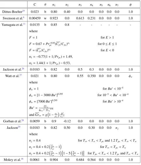
Researchers have found different values forC,n1 &n2 and expression forF. The factorF
wall. The summary of all the heat transfer correlations for supercritical water flow in circular
tubes is given in Table3.1.
Table 2.1: Parameters corresponding to Heat Transfer correlations
C θ n1 n2 n3 n4 n5 n6 n7 φ
Dittus-Boelter25 0.023 b 0.80 0.40 0.0 0.0 0.0 0.0 0.0 1.0
Swenson et al.8 0.00459 w 0.923 0.0 0.613 0.231 0.0 0.0 0.0 1.0
Yamagata et al.11 0.0135 b 0.85 0.8 - - -
-where
F = 1 forE> 1
F = 0.67+Pr−0.05
pc (Cp/Cpb)
n1 for 0≤ E ≤1
F = (Cp/Cpb)
n2 forE< 0
n1 =−0.77(1+1/Prpc)+1.49,
n2 =1.44(1+1/Prpc)−0.53,
Jackson et al.26 0.0183 b 0.82 0.0 0.5 0.3 0.0 0.0 0.0 1.0
Watt et al.27 0.021 b 0.80 0.0 0.55 0.350 0.0 0.0 0.0 φw
where
φw =1 forBu∗< 10−5
φw =[1−3000Bu∗]0.295 for 10−5 < Bu∗< 10−4
φw =[7000Bu∗]0.295 forBu∗> 10−4
Bu∗ = Gr∞
Re∞2.7Pr∞
0.50
andGr∞ =g
1− ρw
ρ∞
D3
ν∞2
Gorban et al.28 0.0059 b 0.9 -0.12 0.0 0.0 0.0 0.0 0.0 1.0
Jackson29 0.0183 b 0.82 0.50 0.0 0.30 0.0 0.0 nj 1.0
where
nj =0.4 forT∞ <Tw< Tpc and 1.2Tpc < T∞ < Tw
nj =0.4+0.2
T
w
Tpc −1
forT∞ <Tpc <Tw
nj =0.4+0.2
T
w
Tpc −1
h
1−5T∞
Tpc −1
i
forTpc < T∞ < 1.2TpcandT∞ < Tw
2.1. FlowDynamics andHeat transfer studies of supercritical fluid flow 15
2.1.3
Computational Studies
As a cost effective approach, computational studies are also performed to investigate the heat
transfer and fluid flow mechanism in supercritical fluids. The CFD studies for turbulent flows
are generally categorized as: (1) Direct Numerical Simulations (DNS) (2) Large Eddy
Simula-tions (LES) (3) Reynolds Averaged Navier-Stokes (RANS). In DNS, the smallest eddy is fully
resolved and no turbulence models are required to model the Reynolds stresses. However, this
method is computational very expensive and it is not possible for industrial applications with
high Reynolds number flows due to higher computational time and cost. Whereas in RANS, all
the eddies are modelled using turbulence models. RANS method with appropriate turbulence
models is widely used for the industrial applications but some of the fundamental information
about the flow is lost. The LES method is a mix of DNS and RANS. In LES, larger eddies are
fully resolved and smaller eddies are modelled. The filtering functions are used to differentiate
between the smaller and larger eddies. This method is computationally expensive than RANS
but less expensive than DNS. However, it is still not widely used for industrial applications due
to its higher computational resource requirement. In the experimental studies, it is not possible
to extract all the important information regarding turbulence. Hence, DNS studies are used as
numerical experiments to provide the inputs for designing of new turbulence models.12,30
The earlier work to simulate the supercritical fluid flow and heat transfer was carried out
using Prandtl’s mixing length model. Bellmore et al.31 implemented the density fluctuations in
the turbulent transport equations to simulate the flow of near critical para-H2 in vertical tubes.
With the development of two-equationk−model,32,33improved results were found in the nu-merical studies.6,34 Bellinghausen et al.34 implemented the low-Reynolds numberk−model
by resolving the near wall region to consider the enhanced gravitational effects and the results
were in close agreement with the experimental data. Koshizuka et al.6 also carried out
numeri-cal simulations using low-Reynolds numberk−model for the deteriorated heat transfer case and the satisfactory comparison was found with the experimental results of Yamagata et al.11
of k−ω model is in near wall region where no damping functions have to be used as in the low-Reynolds number k − model. However, the k −ω model35 is sensitive to free stream
conditions. To combine the strength ofk− andk−ω model, Menter36 proposed a method of blending function. This blending function uses thek− model in free stream and switches tok−ωmodel in the boundary layer region. This model is known as k−ωS S T model. The modification of the originalk−ωmodel tok−ωS S T model sparked interest in researchers to simulate the supercritical fluids using thek−ωS S T model.37–41
Yang et al.37 performed numerical simulations for the heat transfer in supercritical water
flow in circular tubes usingk−ωandk−ωS S T model. It was reported that both the models fail to predict the heat transfer coefficient near the PCR. However, the results were found to be
better than the low-Reynolds numberk− model.
Palko et al.38,40 performed the numerical simulations using k− ωS S T model and
com-pared the results with the experiments of Onratskij et al.16 and Shitsman.14 The numerical
simulations were able to predict the deteriorated heat transfer and the results showed that the
buoyancy and variation in thermal conductivity have significant effect on the heat transfer
dete-rioration phenomenon. However, it was also indicated that these are not the only mechanisms
governing the heat transfer deterioration phenomenon. The influences of the density variation
and acceleration were not studied in their study owing to the limitations of solver, but it was
recommended for the further investigation.
Cheng et al.39 performed the numerical simulations using ω type turbulence models and compared the results with the experimental data of Yamagata et al.11 The ω type turbulence
models failed completely to predict the heat transfer coefficient, which might be because of
not taking variation in the property of fluid into consideration while implementing theωtype turbulence models. Hence, these models with automatic wall treatment were not recommended
to be used for further applications of supercritical fluid flows.
2.2. ControlSystemStudies 17
where normal stress in each direction is equal. Although the modelling process is simplified
due to this assumption, 2-equation turbulence models can not predict anisotropic behaviour of
turbulence stresses. Researchers have also explored the use of anisotropic turbulence models
for simulating supercritical fluid flow.39,42 Zhang et al.42 implemented the Reynolds Stress
Model (RSM) in numerical simulations and compared the results with three different sets of
experimental results for supercritical water and CO2 flowing in circular tubes. Along with
RSM, five other isotropic turbulence models are also validated in this study and it is found that
the RSM performs better than all other turbulence models. Similarly, excellent agreement with
the experimental results were found by Cheng et al.39 when variants of RSM by Launder (LRR)
and Speziale (SSG) were implemented in their numerical simulations. Considering the physics
behind the development of turbulence models, anisotropic turbulence models are expected to
perform better than the isotropic turbulence models. However, the anisotropic models have not
been validated extensively by researchers. To assess the capability of the turbulence models,
validation with the experiments of broad range of operating conditions is important.
2.2
Control System Studies
The several studies have been carried out for the SCWR’s thermal-hydraulic analysis, safety
analysis, materials study, instability analysis and fuel channel design. However, there are not
adequate studies done in the direction of dynamic analysis and control system design of the
SCWR. The SCWR is similar to boiling water reactor (BWR) considering the aspect that both
are direct cycle reactors. The SCWR also shares the similarity with the pressurized water
re-actor (PWR) considering the high operating pressure and single phase flow. Although SCWR
has similarities of both BWR and PWR, it also has unique feature of high heat flux to mass flux
ratio and sharp changes in thermo-physical properties. Owing to these unique features, SCWR
has strong cross-coupling and high degree of non-linearity in its transient behaviour.
Earlier study for the control system design for supercritical fast reactor (SCFR) was done
Dittus-Boelter correlation in the numerical simulations. Based on the transient simulations, pairing
of the input and output was determined. Based on these pairings, the control strategy used
for BWR was used for the control system design of the SCFR. The trial and error method was
used to tune the controller parameters. The similar approach was also used by Ishiwatari et al.44
for high temperature supercritical light water reactor. In the subsequent work by Ishitawari et
al.,45 the improvements in the feed water controller were proposed for a Fast Reactor.
How-ever, all these studies were designed where multiple input and multiple output (MIMO) system
was converted to single input and single output (SISO) systems using decentralized structure.46
This approach is valid for the weakly coupled systems but the SCWR is highly coupled MIMO
system. The very first approach to decouple the CANDU SCWR MIMO system into multiple
SISO systems was taken by Sun.46
Sun46 has used the simple 1-D model to simulate the transient behaviour of the Canadian
SCWR. Based on the these results, the dynamic relationship was established between the
in-puts and output using system identification technique. Next, the direct Nyquist array method
was implemented to decouple the system and convert to diagonally dominant form using
pre-compensator. Based on the pre-compensated plant, loop compensator was designed for the
system control and stability. The control methodology used by Sun46 is based on the simple
1-D approximation of the reactor. However, more accurate method to simulate the transient
thermal-hydraulic behaviour of SCWR is needed.
2.3
Motivation
As discussed before, the researchers have implemented numerous turbulence models to
nu-merically simulate the thermal-hydraulic behaviour of the supercritical fluids. Among all the
studies, k−ωS S T model is found to be better than thek− models but there is till no con-sensus among researchers regarding the behaviour k− ωS S T model in the PCR. Moreover, the anisotropic models which are found to be better than the 2-equation models by previous
2.3. Motivation 19
Therefore, the extensive validation of a CFD model using RSM andk−ωS S T model is per-formed in this study.
The DHT is very important phenomenon in the supercritical fluid flow and heat transfer.
The most of the numerical models fail to predict the DHT and the corresponding wall
tem-peratures in the DHT zone. Hence, in this study, the DHT phenomenon is analysed using the
turbulent kinetic energy (TKE) and velocity distribution and their effect on heat transfer.
More-over, the acceleration and buoyancy parameters, and different types of pressure drop values are
used to study the occurrence of DHT in supercritical fluid flows.
Earlier control system studies for SCWR used the simple 1-D model for establishing the
relationship between the inputs and outputs. The MIMO SCWR system is approximated by
many researchers to multiple SISO systems ignoring the coupling involved. Therefore, in the
present study, CFD simulations are performed to find the relationship between input and
out-puts. Furthermore, the decoupling methodology is used to make the MIMO system diagonally
dominant and finally converting it to multiple SISO systems to facilitate the control system
References
[1] WB Hall and JD Jackson. Laminarization of a turbulent pipe flow by buoyancy forces.
InMechanical Engineering, volume 91, page 66. ASME-AMER SOC MECHANICAL ENG 345 E 47TH ST, NEW YORK, NY 10017, 1969.
[2] H Tanaka, A Tsuge, M Hirata, and N Nishiwaki. Effects of buoyancy and of acceleration
owing to thermal expansion on forced turbulent convection in vertical circular tubes
crite-ria of the effects, velocity and temperature profiles, and reverse transition from turbulent
to laminar flow. Journal of Heat and Mass transfer, 16(6):1267–1288, 1973.
[3] AA Bishop, RO Sandberg, and LS Tong. Forced-convection heat transfer to water at
near-critical temperatures and supernear-critical pressures. Technical report, Westinghouse Electric
Corp., Pittsburgh, Pa. Atomic Power Div., 1964.
[4] JW Ackerman. Pseudoboiling heat transfer to supercritical pressure water in smooth and
ribbed tubes. Journal of Heat transfer, 92(3):490–497, 1970.
[5] V Chatoorgoon. Stability of supercritical fluid flow in a single-channel natural-convection
loop. International Journal of Heat and Mass Transfer, 44:1963–1972, 2001.
[6] S Koshizuka, N Takano, and Y Oka. Numerical analysis of deterioration phenomena in
heat transfer to supercritical water. International Journal of Heat and Mass Transfer, 38(16):3077–3084, 1995.
[7] B Shiralkar and P Griffith. The effect of swirl, inlet conditions, flow direction, and tube
diameter on the heat transfer to fluids at supercritical pressure. Journal of Heat Transfer, 92(3):465–471, 1970.
[8] HS Swenson, JR Carver, and CR Kakarala. Heat transfer to supercritical water in
smooth-bore tubes. Journal of Heat Transfer, 87(4):477–483, 1965.
[9] WB Hall and JD Jackson. Heat transfer near the critical point. keynote lecture. pages
References 21
[10] H Li, H Wang, Y Luo, H Gu, X Shi, T Chen, E Laurien, and Y Zhu. Experimental
investigation on heat transfer from a heated rod with a helically wrapped wire inside
a square vertical channel to water at supercritical pressures. Nuclear Engineering and Design, 239(10):2004–2012, 2009.
[11] K Yamagata, K Nishikawa, S Hasegawa, T Fuji, and S Yoshida. Forced convective
heat transfer to supercritical water flowing in tubes. Journal of Heat and Mass trans-fer, 15(12):2575–2593, 1972.
[12] JH Bae, JY Yoo, and H Choi. Direct numerical simulation of turbulent supercritical flows
with heat transfer. Physics of Fluids, 17(10):105104, 2005.
[13] JY Yoo. The Turbulent Flows of Supercritical Fluids with Heat Transfer. Annual Review of Fluid Mechanics, 45:495–525, January 2013.
[14] ME Shitsman. Impairment of the heat transmission at supercritical pressures(heat
trans-fer process examined during forced motion of water at supercritical pressures). High Temperature, 1:237–244, 1963.
[15] LF Glushchencko, SI Kalachev, and OF Gandzyuk. Determining the conditions of
ex-istence of deteriorated heat-transfer at supercritical pressure of medium. Thermal Engi-neering, 19(2):107–111, 1972.
[16] AP Ornatskij, LF Glushchenko, and SI Kalachev. Heat transfer with rising and falling
flows of water in tubes of small diameter at supercritical pressures.Thermal Engineering, 18(5):137–141, 1971.
[17] AM Shehata and DM McEligot. Mean structure in the viscous layer of strongly-heated
internal gas flows measurements. International Journal of Heat and Mass Transfer, 41(24):4297–4313, 1998.
[18] S Mokry, I Pioro, A Farah, K King, S Gupta, W Peiman, and P Kirillov. Development of
[19] VA Kurganov and AG Kaptil’ny. Velocity and enthalpy fields and eddy diffusivities in a
heated supercritical fluid flow. Experimental Thermal and Fluid Science, 5(4):465–478, 1992.
[20] I Wardana, T Ueda, S Kurihara, and M Mizomoto. Turbulence structure in an annuli with
strongly heated inner cylinder. Experiments in Fluids, 27(2):137–144, 1999.
[21] S Kang, B Patil, JA Zarate, and RP Roy. Isothermal and heated turbulent upflow in a
vertical annular channel–part i. experimental measurements. International Journal of Heat and Mass Transfer, 44(6):1171–1184, 2001.
[22] J Licht, M Anderson, and M Corradini. Heat transfer and fluid flow characteristics in
supercritical pressure water. Journal of Heat Transfer, 131(7):072502, 2009.
[23] YY Bae and HY Kim. Convective heat transfer to co2 at a supercritical pressure flowing
vertically upward in tubes and an annular channel. Experimental Thermal and Fluid Science, 33(2):329–339, 2009.
[24] IL Pioro, HF Khartabil, and RB Duffey. Heat transfer to supercritical fluids flowing in
channels, empirical correlations (survey).Nuclear Engineering and Design, 230(1-3):69– 91, 2004.
[25] FP Incropera. Introduction to heat transfer. John Wiley & Sons, 2011.
[26] JD Jackson and J Fewster. Forced convection data for supercritical pressure fluids. Heat Transfer Fluid Flow Science 21540, Harwell, UK, 1975.
[27] MJ Watts and CT Chou. Mixed convection heat transfer to supercritical pressure water.
InProceedings of the 7th International Heat Transfer Conference. Vol 3, pages 495–500, 1982.
[28] LM Gorban, RS Pomet’ko, and OA Khryaschev. Modeling of water heat transfer with
References 23
[29] JD Jackson. Consideration of the heat transfer properties of supercritical pressure water
in connection with the cooling of advanced nuclear reactors. InProc. 13th Pacific basin Nuclear Conference, Shenzhen City, China, pages 21–25, 2002.
[30] JH Bae, JY Yoo, and DM McEligot. Direct numerical simulation of heated co2 flows at
supercritical pressure in a vertical annulus at re=8900. Physics of Fluids (1994-present), 20(5):055108, 2008.
[31] CP Bellmore and RL Reid. Numerical prediction of wall temperatures for near-critical
para-hydrogen in turbulent upflow inside vertical tubes. Journal of Heat Transfer, 105(3):536–541, 1983.
[32] WP Jones and BE Launder. The prediction of laminarization with a two-equation model
of turbulence. International Journal of Heat and Mass Transfer, 15(2):301–314, 1972.
[33] BE Launder and BI Sharma. Application of the energy-dissipation model of turbulence to
the calculation of flow near a spinning disc. Letters in heat and mass transfer, 1(2):131– 137, 1974.
[34] R Bellinghausen and U Renz. Pseudocritical heat transfer inside vertical tubes.Chemical Engineering and Processing: Process Intensification, 28(3):183–186, 1990.
[35] DC Wilcox. Reassessment of the scale-determining equation for advanced turbulence
models. AIAA journal, 26(11):1299–1310, 1988.
[36] FR Menter. Zonal two equation k-turbulence models for aerodynamic flows.AIAA paper, 2906:1993, 1993.
[37] J Yang, Y Oka, Y Ishiwatari, J Liu, and J Yoo. Numerical investigation of heat transfer in
upward flows of supercritical water in circular tubes and tight fuel rod bundles. Nuclear Engineering and Design, 237(4):420–430, February 2007.
[38] D Palko and H Anglart. Theoretical and numerical study of heat transfer deterioration in
[39] X Cheng, B Kuang, and YH Yang. Numerical analysis of heat transfer in supercritical
water cooled flow channels.Nuclear Engineering and Design, 237(3):240–252, February 2007.
[40] D Palko and H Anglart. Deteriorated heat transfer at low coolant flow rates. In Interna-tional Students Workshop on HPLWR, pages 1–4, 2008.
[41] QL Wen and HY Gu. Numerical investigation of acceleration effect on heat transfer
deterioration phenomenon in supercritical water.Progress in Nuclear Energy, 53(5):480– 486, 2011.
[42] Y Zhang, C Zhang, and J Jiang. Numerical simulation of heat transfer of supercritical
fluids in circular tubes using different turbulence models.Journal of Nuclear Science and Technology, 48(3):366–373, 2011.
[43] T Nakatsuka, Y Oka, and S Koshizuka. Control of a fast reactor cooled by supercritical
light water. Nuclear technology, 121(1):81–92, 1998.
[44] Y Ishiwatari, Y Oka, and S Koshizuka. Control of a high temperature supercritical
pres-sure light water cooled and moderated reactor with water rods.Journal of Nuclear Science and Technology, 40(5):298–306, 2003.
[45] Y Ishiwatari, C Peng, S Ikejiri, and Y Oka. Improvements of feedwater controller for the
super fast reactor.Journal of Nuclear Science and Technology, 47(12):1155–1164, 2010.
Chapter 3
Numerical Models to Predict Steady and
Unsteady Thermal-hydraulic Behaviour of
Supercritical Water Flow in Circular
Tubes
Abstract
The present paper is aimed at the development of numerical models to predict steady and
un-steady thermal-hydraulic behavior of supercritical water flow at various operating conditions.
A simple one-dimensional numerical thermal-hydraulic model based on a finite-difference
scheme has been developed. A detailed computational fluid dynamic (CFD) analysis based on
two turbulence models, Reynolds Stress Model andk−ωS S T model, has also been presented in this paper. Seven experimental cases of steady state and vertically up flowing supercritical
water in circular tubes operated at various working regimes, such as normal and deteriorated
heat transfer regions, are used to validate the numerical models. Comparisons for steady state
flow show good agreement between the numerical and experimental results for all normal heat
transfer cases and most of the deteriorated heat transfer cases.
Next, the numerical models are used for transient simulations. Three case studies are
un-dertaken with a purpose to quantify the time dependent responses from both the 1-D model and
CFD model. The comparisons carried out for both the normal and deteriorated heat transfer
conditions show good agreement between the two numerical models.
Keywords:supercritical water, numerical models, deteriorated heat transfer, steady state,
27
Nomenclature
a Acoustic speed, m/s
A Area,m2
cp Specific heat capacity at constant pressure,J/kg K
cp (hw−hb)/(Tw−Tb), J/kg K
D Diameter of a tube,m
e Specific internal energy, J/kg g Gravitational acceleration,m/s2 G Mass flux,kg/m2s
h Specific enthalpy,J/kg
h∞ Heat transfer coefficient,W/m2oC
k Turbulence kinetic energy,m2/s2
L Length,m
Lh Heated length,m
p Pressure,Pa
Pw Wetted perimeter,m
qw Wall heat flux,W/m2
q0w Wall heat per unit length,W/m
r Distance from the centre of the tube,m r∗ Non-dimensional radial location
t Time,s
T Temperature,o
C u Velocity,m/s W Mass flow rate, kg/s
y Distance from the wall,m
y+ Non-dimensional distance from the wall,uτy/ν,m
z Axial location,m
Greek Letters
α Thermal expansion coefficient, 1/K
Energy dissipation per unit mass,m2/s3
λ Thermal conductivity,W/mK
µ Dynamic viscosity,Pa s
ν Kinematic viscosity,m2/s
ρ Density of a fluid,kg/m3
τ Shear stress ;τw, wall shear stress,N/m2
ω Specific dissipation rate, 1/s
Subscripts
cr Value at critical point
dht Deteriorated heat transfer
ex Exit
exp Experimental data
f Values at film, reference values between y=0 and y=y
in Inlet
m Mean
num Numerical
pc Pseudo-critical
q Based on local heat flux value
t Turbulent
w Wall
29
Dimensionless Numbers
Bu∗ Buoyancy Parameter,Grb/Re2b.7Prb
0.50
Grb g(1−ρw/ρb)D3/νb2
Nu Nusselt Number
Pr Prandtl Number,µcp/k
Pr µcp/k
Acronyms
AECL Atomic Energy of Canada Limited
BC Boundary Condition
BWR Boiling Water Reactor
CFD Computational Fluid Dynamics
DHT Deteriorated Heat Transfer
HTC Heat Transfer Coefficient
HTCD Heat Transfer Coefficient by Dittus - Boelter
HTCJ Heat Transfer Coefficient by Jackson et al.
HTCM Heat Transfer Coefficient by Mokry et al.
HTCS Heat Transfer Coefficient by Swenson et al.
HTCW Heat Transfer Coefficient by Watts et al.
MAE Mean Absolute Error
NHT Normal Heat Transfer
PCR Pseudo Critical Region
RSM Reynold Stress Model
SCR Supercritical Reactor
SCW Supercritical Water
SCWR Supercritical Water Cooled Reactor
SD Standard Deviation
SST Shear Stress Transport
TH Thermal-Hydraulic
THRUST Thermal-Hydraulic solveR UndertakingSupercritical waTer
3.1. Introduction 31
3.1
Introduction
The supercritical water cooled reactor (SCWR) has been identified as one of the six proposed
technologies for the Generation IV nuclear reactors1 because of its advantage of high
ther-mal efficiency, compact plant system, avoidance from boiling crisis and close proximity to the
proven technology of supercritical fossil power plants. Therefore, SCWR has received
atten-tion among the researchers of various disciplines at present. The fluid flow and heat transfer
characteristics and the thermo-physical properties of various substances, such as water and
CO2, at supercritical conditions have been studied extensively since 1950s, such as the
exper-imental research works carried out by Yamagata et al.,2 Swenson et al.,3 Jackson4 and many
more as mentioned in the review papers by Duffey and Pioro,5Pioro et al.6 and Jager et al.7
However, there are still issues need to be addressed in order to meet the present demand of
mak-ing the SCWR technologically viable and economically feasible with adequate safety margin
and to predict its behavior accurately at normal and anticipated accidental operating situations.
In addition to the numerous experimental studies, economically attractive alternatives, the
numerical approaches have been used extensively in recent years to get detailed insight into the
heat transfer mechanism in supercritical fluids. In numerical studies, two approaches can be
used - (i) CFD models and (ii) one-dimensional thermal-hydraulic (TH) models. The former
approach is computationally expensive and its main challenge is to implement the accurate
turbulence models for supercritical fluids. However, it can provide detailed information on the
flow and heat transfer in all the directions. While the latter approach, which takes into account
the axial variation of flow and thermodynamic properties, and averages the quantities along
ra-dial and azimuthal directions, is computationally efficient, flexible and may have the required
accuracy if the empirical heat transfer correlation (HTC) are implemented properly.
Earlier numerical studies for supercritical flows using CFD models were done by Deissler
et al.8 and Shiralkar et al.9 using the turbulence models based on eddy diffusivity assumption.
fluids. Later, thek−ωS S T model developed by Menter10which combines the strength ofk−
model in free stream region and strength ofk−ωin recirculating regions is used by various re-searchers, such as Cheng et al.11 and Palko et al.12,13 However, there is no common consensus
among researchers regarding the capability ofk−ωS S T model for studying the heat transfer phenomenon in supercritical fluid flows. Therefore, in the current study,k−ωS S T model will be used to assess its capability in predicting supercritical fluid flows under various operating
conditions. It is important to note that the two-equation turbulence models are developed with
the isotropic assumption. The researchers have also used anisotropic turbulence models such
as the Reynolds Stress Model for supercritical water flow in various geometries.11,14 It was
concluded from these studies that anisotropic turbulence models give better agreement with
experimental results than other two-equation models with isotropic assumption for chosen
ex-perimental conditions. As the turbulence models are sensitive to operating conditions, in the
current study, the turbulence model RSM is also evaluated against experimental data to assess
its capability under different operating conditions. The CFD simulations are carried out using
the commercial software Ansys FLUENT 14.5.
There are several 1-D TH models, such as those developed by Chatoorgoon et al.,15–17
Am-brosini et al.,18 Gomez et al.19 and Jain and Rizwan-uddin.20 But those models were mainly
used to predict the static and dynamic instabilities of supercritical reactors (SCRs) without
giving much attention to evaluate their capability in predicting the wall temperature. The
pre-dicted wall temperature using the 1-D model depends on the empirical HTCs used in the model.
Moreover, there are umpteen number of HTCs available in the literature which are experiment
specific and thus, need validation before using them with TH model.
The reviews conducted by several authors6,21,22showed that the numerically predicted wall
temperature is in good agreement with the experimental data mainly for the normal heat transfer
(NHT) cases. However, for the deteriorated heat transfer (DHT) cases which are characterised
by a sharp increase in the wall temperature, the numerical predictions are found to be
challeng-ing. Therefore, the numerical models presented in this study will be validated for both NHT
3.2. Mathematical details of the numerical models 33
The in-house 1-DThermal-Hydraulic solveR UndertakingSupercritical waTer (THRUST),
which is an extension of an earlier model used for simulating boiling water reactor (BWR),23
is used for SCWR in the present work. It is based on mass, momentum and energy
conserva-tion equaconserva-tions and includes the thermodynamic equaconserva-tion of state to take care of pressure and
temperature dependent property variations.
In this study, the THRUST and CFD models are evaluated by comparing the simulation
results with the experimental data under various operating conditions. Further, both the
nu-merical models are extended to simulate the transient response. Subsequently, the step change
and periodic variation of various physical variables are introduced with a purpose to assess the
capability of the numerical models to predict the heat transfer phenomenon during the transient
process.
3.2
Mathematical details of the numerical models
The mathematical details of the THRUST and CFD models are presented in this section. The
present analysis is carried out under both steady state and transient conditions.
3.2.1
Mathematical formulations of the 1-D TH model
In the 1-D THRUST, it is assumed that the thermo-physical flow properties vary along the
axial direction only and the heat flux at the periphery of the circular tube is constant. The
general fundamental one-dimensional governing equations for fluid flow and heat transfer are
as follows:
Mass conservation equation:
∂
∂t(ρ A)+
∂
Momentum conservation equation in the axial direction:
∂
∂t(ρA u)+
∂ ∂z
ρA u2 = −A ∂p
∂z −τwPw−ρA g dH
dz (3.2)
Energy conservation equation:
∂
∂t(ρ A e)+
∂ ∂z
ρA u ef
= qwPH (3.3)
wheree= ef − p
ρ andef = h+ u
2
2 +gH.
These equations can be written in a compact form as follows:
∂ ∂t
h
Ri+ ∂
∂z
h
Si=h Ti (3.4)
where R= ρA ρAu ρAe
, S=
ρAu Aρu2+ p
ρAu ef
, T=
0
pdAdz −τwPw−ρAgdHdz
qwPH
These governing equations in a conservative form are first converted into the following
primi-tive form:
∂ ∂t
h
Ui+AU ∂
∂z
h
Ui= hDU i (3.5)
whereUis a vector of unknown dependent variables
W, h, pT
,Ais a square matrix of coeffi
-cients which are functions ofU, andDis a vector containing allowances for mass, momentum,
and energy to transfer across the system boundaries.
Equation of state,ρ =ρ(p,h), is used and it is noted that all the thermodynamic properties in the present model are subjected to change depending on the pressure and enthalpy along the
axial direction of the channel.
The eigenvalues of matrixAdetermine the mathematical class of Eq. (3.5) and it is found
that all eigenvalues of A are real (u, u + a, u− a); and hence the governing equations are hyperbolic ones. Next, the set of Eq. (3.5) are transformed into a characteristic form and it can
3.2. Mathematical details of the numerical models 35
B ∂
∂t
h
Ui+Λ B ∂
∂z
h
Ui= hCi (3.6)
whereΛis a diagonal matrix of eigenvalues ofA.
After coefficient and source term linearization, Eq. (3.6) is discretized with a
characteristics-dependent implicit finite-difference scheme where the spatial derivative terms are approximated
by backward or forward difference depending on the sign of the characteristics. For the present
case of subsonic flow (u < a), the spatial derivatives for the first two governing equations, which are characterized byΛ11 = u+a > 0 andΛ22 = u > 0, respectively, are approximated
by backward difference equations and the third governing equation, which is characterized by
Λ33 = u− a < 0, is approximated by forward difference equation. The resultant discretized
equations are then combined together and used for numerical solution depending on the
bound-ary conditions for the particular problem.
Steady state solution methodology
The resultant discretized equations for Eqs.(3.1)-(3.3) for steady state flows are as follows:
ρi+1Ai+1ui+1 = ρiAiui (3.7a)
pi−pi+1 =
1 2
1
Ai
+ 1
Ai+1 !
h
ρAu2
i+1−
ρAu2
i
i
+ 1
2
hn
ρ(F+g)o
i+
n
ρ(F+g)o
i+1 i
(zi+1−zi) (3.7b)
(ef)i+1−(ef)i =
1 2
"
q0w
ρAu ! i + q 0 w ρAu !
i+1 #
(zi+1−zi) (3.7c)
The above set of equations, in addition to the thermodynamic equation of state, are solved
numerically by using a forward marching scheme when all the inlet primary variables, i.e.,
inlet velocity, enthalpy and pressure are specified, otherwise a shooting method along with the
forward marching scheme is employed to treat different set of specified boundary conditions.
Heat transfer coefficient and friction factor
The accuracy of such a 1-D TH model largely depends on appropriate selection of friction