Parametric Trojans for Fault-Injection Attacks on
Cryptographic Hardware
Raghavan Kumar$, Philipp Jovanovice, Wayne Burleson$ and Ilia Poliane
$University of Massachusetts Amherst, 01002, USA eUniversity of Passau, 94032, Germany
{rkumar|burleson}@ecs.umass.edu, {philipp.jovanovic|ilia.polian}@uni-passau.de
Abstract—We propose two extremely stealthy hardware Trojans that facilitate fault-injection attacks in crypto-graphic blocks. The Trojans are carefully inserted to modify the electrical characteristics of predetermined transistors in a circuit by altering parameters such as doping concentration and dopant area. These Trojans are activated with very low probability under the presence of a slightly reduced supply voltage (0.001 for 20% Vdd reduction). We demonstrate the effectiveness of the
Trojans by utilizing them to inject faults into an ASIC implementation of the recently introduced lightweight cipher PRINCE. Full circuit-level simulation followed by differential cryptanalysis demonstrate that the secret key can be reconstructed after around 5 fault-injections.
Keywords-fault-based cryptanalysis, fault injection, hardware Trojans
I. INTRODUCTION
Hardware Trojans are malicious modifications of a circuit by an untrusted third-party manufacturer that aim at manipulating its behavior in an undesired manner [1]. A Trojan may deactivate the circuit (denial-of-service), change its functionality, or establish a hidden side chan-nel through which protected secret information processed by the circuit is leaked. Trojans may be activated by external events (e. g., applying a specific combination of logic values to the circuit inputs) or internal events (for instance, a counter reaching a certain value). In general, Trojans are designed to be stealthy, that is, to escape detection by methods such as testing [2], optical inspection [3] or side-channel analysis [1].
In this paper, we introduce two types of Trojans that are optimized for fault-based attacks on circuits that implement cryptographic functions. In the course of a fault-based attack [4], physical disturbances are introduced into the circuit when it runs the cryptographic algorithm. The fault-affected output values are collected, and differential cryptanalysis is used to derive the secret key. Recently, a number of highly efficient attacks on
state-of-the-art ciphers including AES [5], LED [6], [7], PRESENT [8] and PRINCE [7], [9] have been reported. These attacks need a small number of fault injections (1 for AES and LED64, around 3–4 for LED128 and PRINCE) for successful key recovery. However, fault injection must be precise: both the location and the time of the disturbance have to be well-controlled. Low-cost fault-injection techniques like Vdd reduction or clock
manipulation do not achieve the required accuracy, while highly precise methods such as pinpointed irradiation of desired fault sites by intensive laser light are difficult to perform and require costly equipment [10].
We call the Trojans introduced in this work
MAnufacturing-Process-LEvel Trojans, or MAPLE Tro-jans. They are based on manipulating the voltage-transfer characteristics (VTC) of a specific gate in the circuit by changing the doping concentration or reducing the dopant area within the active area of its transistors. The idea of dopant-level Trojans was recently introduced in [11] and used to manipulate both the functionality and the non-functional properties of the affected gates and memory elements. Our MAPLE Trojans inherit some properties of the Trojan from [11]; in particular, the layout of the circuit is not changed and the Trojans are nearly impossible to detect by optical inspection. However, the Trojans in [11] resulted in a deterministic change of the affected gate’s function, similar to the effect of a stuck-at fault, and can be detected by testing.1
In contrast, our Trojans only slightly shift the Vin-Vout
characteristic of the gate. The resulting faults are rare and therefore highly unlikely to be detected during testing, while at the same time sufficient for a successful fault-based attack.
We demonstrate the fault-based attack on the recent
1
lightweight cipher PRINCE [12]. The attack [7] works in multiple stages and requires two or three fault injec-tions into the 8th round (out of 10) and several further (between 2 and 11, roughly 3 on average) fault injections into the 9th round of PRINCE. In order to be exploitable for the attack, the injected faults must adhere to several conditions, and the faults in the 8th and the 9th round maynotbe present at the same time. MAPLE Trojans are applied to three inverters that belong to the 8th round of PRINCE and three further inverters from the 9th round. Trojans are activated by a slight reduction of Vdd, with
the probability of activation being around 10−5 for 10% reduction and around 10−3 for 20% reduction.
The multi-stage attack is particularly challenging for the MAPLE Trojan insertion because a fault may be injected in the 8th and in the 9th round at the same time and such double faults are not exploitable. We demonstrate the feasibility of the attack using both a combinational (one clock cycle per encryption) and a se-quential (one cycle per round, 10 cycles per encryption) implementation of the circuit. We simulate the PRINCE circuit incorporating the manipulated six inverters on electrical level and hand the observed outputs to a soft-ware routine that performs the differential cryptanalysis and derives the secret key. In the combinational circuit, the percentage of exploitable faults is around 10%. This means that around 10,000 to 1,000,000 encryptions are sufficient to obtain an exploitable fault, depending on the used amount of Vdd reduction. This is clearly
feasible as one encryption takes one clock cycle. In the sequential implementation, the correlation is much lower, the percentage of exploitable faults is higher but the duration of one encryption is longer, so the overall effort is comparable to the combinational case.
The remainder of the paper is organized as follows. Background on Trojans is provided in the next section. Section III provides details on the MAPLE Trojans. The threat model, detectability methods and the possible countermeasures are provided in section IV. Section V explains the fault attack on the PRINCE circuit. Results are reported in Section VI. Section VII concludes the paper.
II. HARDWARE TROJANS ANDTHEIRDETECTION
Apart from register transfer level (RTL) modifications, Trojans can also be inserted to an IC by the malicious foundry. As the foundry doesn’t have access to the RTL code, the modifications are made in the layout mask and process level [11], [13]. The Trojans proposed in [13] affect the reliability of CMOS circuits by accelerating
wear-out mechanisms such as Negative Bias Tempera-ture Instability (NBTI) and Hot Carrier Injection (HCI) effects. To insert the Trojans, the manufacturing process conditions are slightly altered. The recently reported layout-level Trojans in [11] involve modification of the dopant polarities in the active-area of a transistor and are extremely difficult to discover by functional testing. By applying the Trojan to a random number generator (RNG) from Intel, the authors demonstrate that the entropy of the RNG can be reduced but in a way that is not noticed by the on-chip self-test block.
Most of the hardware Trojans inserted into an IC can be detected using either side-channel or activation mechanisms [1]. As the Trojans typically have para-metric effects on the circuit including changes in delay and power consumption profile, they can be detected by power- and timing-based side-channel analysis (SCA) [2]. These techniques require comparison of the mod-ified chip with a golden chip. So, the effectiveness of these techniques are often affected by increasing process variations in integrated circuits. An IC can have millions of paths, which can make timing-based SCA impractical. Another way to detect Trojans is by functional testing, in which the Trojans are activated by test patterns. One of the problems involved in functional testing is the lack of information about the inserted Trojan, which can increase the complexity involved in test pattern generation.
III. MAPLE TROJANS
In this section, we present efficient techniques for inserting Trojans to an IC to facilitate fault attacks. The proposed hardware Trojans are based on the modification of a logic gate’s electrical characteristics in such a way that the metal, polysilicon layer and active area remain unchanged. This is essential to render them hard to detect by optical inspection, as changes in the above mentioned layers can be detected reliably by inspection [11]. To alter the gate’s electrical characteristics, we exploit doping concentration and dopant area within the active area of a transistor. As the proposed Trojans are either in manufacturing level or layout-level and also introduce changes in electrical characteristics, they fall under the category ofparametric Trojans [1]. We use an inverter as the target logic gate to explain the proposed Trojan insertion techniques.
A. Doping Concentration Manipulation
In this hardware Trojan insertion technique, the Vin
target logic gate is modified by changing the doping concentration in the channel region. The channel doping concentration of the n-MOS and p-MOS transistors is one of the major factors that determine the threshold voltage of the transistors and therefore the VTC of the logic gate. The malicious foundry could create a Trojan gate, e.g., an inverter with a manipulated VTC, by reducing the doping concentration. This is illustrated in Figure 1. As shown in Figure 4, the threshold voltages of the transistors in an inverter are increased and the inverter exhibits a reduced voltage swing. This results in a shift in switching threshold. We call this type of gate modification TrojanConc and denote the switching threshold of the Trojan gate by Vm. We define switching
threshold as the input voltage (Vin) at which the output
voltage (Vout) is around 0.5 V, although TrojanConc
exhibits a reduced output voltage swing. The shift inVm
will have a significant impact on the gate being driven by the Trojan as explained in section III-C.
Fig. 1. Cross-sectional view of (a) original inverter and (b) Trojan
inverter using doping concentration manipulation
B. Dopant Area Manipulation
A different Trojan inverter can be created by reducing the dopant area within the active area of a transistor [11]. This effectively weakens a transistor and pushes the VTC towards the weakened transistor. For example, by reducing the dopant area of the n-MOS transistor in an inverter, a Trojan with a VTC shown in Figure 4 can be created and we call this type of gate modification as
TrojanArea. A similar Trojan inverter can be created by reducing the dopant area within the p-MOS transistor. The layouts of the normal inverter and TrojanArea are shown in Figure 3. The shift in switching voltage (Vm)
for TrojanAreais shown in Figure 4. In our analysis, we observed that the maximum shift inVmfor the Trojans is
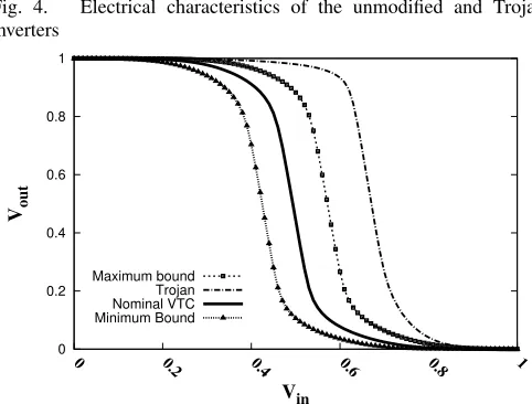
significantly higher than the shift observed due to process variations (3σ ≈150 mV for 45 nm CMOS technology [14]). The resulting VTCs with process variations (both the maximum and minimum bounds) are shown in
Fig-ure 5. Note that the VTC of the Trojan is far from the shifted VTCs due to process variations and hence the faults induced into the circuit will be most likely from the Trojans at slightly reduced Vdd.
Fig. 2. Layout of (a) original inverter and (b) Trojan inverter using
dopant polarity manipulation from [11]
Fig. 3. Layout of (a) original inverter and (b) Trojan inverter using
dopant area manipulation
C. Trojan Activation
The proposed Trojans are activated in the presence of slightly reduced supply voltage. If the supply voltage is noisy enough, then the Trojan inverter will flip its state, when the supply voltage crosses the switching threshold. To ensure that only the Trojan gate flips the state, the switching threshold of the Trojan should be pushed far away from the original threshold. The switching probability ortrigger factor under variousVdd
0 0.5 1
0 0.2 0.4 0.6 0.8 1
V
out
Vin ∆Vm
No Trojan TrojanConc TrojanArea Dopant Trojan[11]
Fig. 4. Electrical characteristics of the unmodified and Trojan
inverters
0 0.2 0.4 0.6 0.8 1
0 0.2 0.4 0.6 0.8 1
Vout
Vin
Maximum bound Trojan Nominal VTC Minimum Bound
Fig. 5. Impact of process variations on Nominal VTC and the Trojan VTC
model the noisy supply voltage as a Gaussian distribution with a 3σ deviation of ±10% of the meanVdd. We can
infer that the trigger factor is sufficiently low (<10−6) when Vdd is reduced from its nominal value of 1 V to
0.9 V. This means that the Trojan inverter approximately produces a faulty bit (bit-flip) with a probability of10−6. Note that the activation of the MAPLE Trojans pro-posed in this paper is fundamentally different from the technique in [11], even though it works on process level. The manipulation from [11] is based on a complete change of dopant polarities and results in a “stuck-at” behavior, that is, constant voltage at the inverter output independent of the voltage at its input (see the Trojan in Figure 2 and VTC in Figure 4). This behavior results in deterministic fault injection which is detectable by func-tional testing. In contrast, the MAPLE Trojans from this section are activated stochastically, with low probability controlled by the extent of manipulation (actual change in dopant area or doping concentration). This allows fault injection with a rate that is still sufficient for practical
0.0001 0.001 0.01 0.1 1 10 100
0.65 0.7 0.75 0.8 0.85 0.9 0.95
Trigger factor (%)
Vdd
TrojanConc TrojanArea
Fig. 6. Triggering factor of the Trojan inverters
cryptanalysis but makes the detection infeasible, as dis-cussed in Section IV. Also, [11] discusses about Dopant-area Trojans from side-channel perspective (reducing dopant area within the active area of a transistor) and we focus only on transient fault-injection rather than a side-channel perspective. Conventional functional test methods are based on the notion of fault coverage: a fault that did not manifest itself during test is considered to be absent from the circuit. This approach is not applicable in case of non-deterministic faults which show up with low probability, such as the faults due to MAPLE Trojans. We are not aware of earlier Trojan insertion techniques that employ probabilistic behavior to resist detection while still being useful for an actual attack.
As the main objective of our Trojans is to facilitate fault-based attacks in cryptographic circuits, we apply the presented Trojan insertion techniques over a recently introduced block cipher known as PRINCE [12]. The details on fault injection and cryptanalysis are presented in Section V. In the next section, we outline the threat model and discuss possible countermeasures.
IV. THREATMODEL ANDCOUNTERMEASURES
“back-doors” in security-relevant IP and could use MAPLE Trojans to implement such backdoors. In the following section, we outline the capabilities needed by the manu-facturer and by the attacker to exploit MAPLE Trojans, their detectability and countermeasures.
A. Threat Model
In order to manipulate gates using TrojanConc or
TrojanArea techniques, the malicious manufacturer has to be able to use masks that deviate from the GDS II layout files received from the circuit designer. This is not a limitation, as most manufacturers perform optical proximity correction and other post-processing in order to improve the manufacturability of the circuit, and these modifications are not communicated back to the designer. Realizing TrojanArea requires a slight modifi-cation of one mask and can be done in a very stealthy way (only the engineer working with the mask will know about the modification). ImplementingTrojanConc
requires a substantial modification of dopant concentra-tion. This is technically feasible: the doped areas of the manipulated gates must undergo implanting for a different amount of time than the doped area of all other gates. The same approach is used to implement low-Vt and high-low-Vt transistors within the same design, even though the concentrations used for TrojanConc are far outside the regular specifications (doping concentrations have been reduced by 1000x for synthesizing the Trojan in Figure 4). An additional set of masks and new process steps which are not performed for a Trojan-free circuit are needed to implement TrojanConc. Therefore, the effort is more significant (though realistic), and more employees will know about the manipulation.
State-of-the-art fault-injection attacks require precise knowledge of the location of the fault, that is, the manipulated logic gate(s). For example, in the case study used later in this paper, six inverters known to be driving specific state bits are manipulated while all other gates are left untouched. In this paper, we follow Kerckhoff’s principle, i.e. “the enemy knows the system”, which is usually assumed in security analysis. In practice, the ma-licious manufacturer may not have a functional gate-level description of the circuit and will first have to find out the location of the gate(s) to be manipulated within the GDS II layout. This is a classical reverse-engineering problem which can be solved given sufficient resources. The circuit designer can complicate reverse-engineering by using obfuscation techniques. In general, a manufacturer who knows that the circuit must include a cryptographic block should be able to locate characteristic structures
of such a block within the larger layout.
After the Trojan-affected circuit has been manufac-tured, mounting the attack involves simply running the circuit at a slightly lowered Vdd. As pointed out in
Section III-C, the Trojan will trigger with a rather low probability of < 10−6 for 10% Vdd reduction. This
means that the operation has to be repeated several thou-sand times until a fault-injection takes place. Therefore, the attacker needs the capability to control the Vdd and
to repeat the computation multiple times assuming that the same secret key is used. These capabilities do not require any non-trivial equipment or skills.
B. Detection
The key characteristic of the MAPLE Trojans is their ultra-low detectability by all known means: functional testing, side-channel analysis, and visual inspection. We elaborate on the detectability aspects in detail.
1) Functional testing under nominal Vdd: Since the
Trojans are not activated under nominalVdd, they cannot
be detected during regular post-manufacturing testing.
2) Functional testing under slightly reduced Vdd:
It appears promising to detect the Trojans under their activation conditions, namely slightly reducedVdd.
Low-voltage testing is feasible and is often performed in practice [15]. However, recall that the activation of the Trojans is probabilistic and the likelihood of activation (trigger factor) is as low as10−6 for 10%V
ddreduction.
It is acceptable for the attacker, who knows the location of the Trojan gate and its expected trigger factor, to perform the well-defined attack several thousand times. In contrast, the party who runs the test (e. g., the system integrator) neither knows whether a MAPLE Trojan or any other Trojan is present in the circuit at all, nor where it might be located, nor whether the trigger factor is
<10−5,<10−4, <10−6 or any other value. Repeating
the test several thousand times based just on vague suspicions is generally incompatible with economical aspects. Even if the test is applied and no fault is observed, it is not clear whether the circuit is Trojan-free or a Trojan is present but its trigger factor is so low that more repetitions are required. Finally, if several thousands of tests are indeed performed and a faulty effect is observed, it is easily confused with a random transient fault due to noise or radiation, rather than a Trojan.
3) Functional testing under significantly reducedVdd:
increased by further lowering the operating voltage. However, ifVddis lowered far beyond its nominal value,
the switching delays of the gates on the circuit paths will be increased and the circuit will exhibit regular timing errors. Consequently, if failures are observed, it does not appear feasible to distinguish the effects of the activated Trojan from that of regular failures.
4) Side-channel analysis (parametric test): The ma-nipulated logic gates have a parametric response that is clearly different from regular gates. If one manip-ulated gate would be considered in isolation, it would be easily distinguished from non-manipulated gates by, for instance, IDDQ testing. This is true forTrojanConc
and, in particular, TrojanArea. However, the number of manipulated gates will be low: for example, only six inverters are affected in the case study in this paper, and that block will be likely integrated into an even larger circuit. Therefore, the effect of few manipulated gates will be negligible compared withIDDQdrawn elsewhere
on the chip and cannot be measured in presence of even minimal variability.
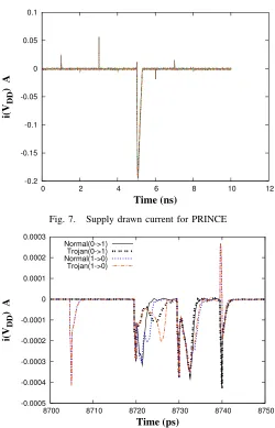
In order to illustrate low detectability of MAPLE Trojans by IDDQ testing, we simulated the circuit of
cipher PRINCE used in Section V-D. Figure 7 shows the current drawn from the supply during ten encryptions using random key and plaintext. The peak in the profile corresponds to the latching of key and plaintext into the corresponding registers right before the start of the encryption. The Trojan inverters inserted into PRINCE are under operation between the time duration 8.7 and 8.75ns, and this period is magnified in Figure 8. The current profile shows the supply drawn current for both the unmodified (“Normal”) and Trojan inverters for the possible input patterns (0 → 1 and 1 → 0). It can be seen from the figure that all deviations in drawn current are absolutely minimal and will likely be masked by the IDDQ drawn in other parts of the chip. Note that
the process variations have not been accounted in this analysis and they can further impede the side-channel analysis using IDDQ profiles.
5) Optical inspection: The Trojans are highly im-mune to detection by optical inspection, as the metal, polysilicon and active area remain unchanged [3].
C. Other countermeasures
1) On-chip voltage detectors: Some cryptographic devices are protected by voltage detectors in order to identify fault injection by Vdd manipulation. However,
the activation of the presented Trojans requires only very moderate Vdd reduction to values that are routinely
-0.2 -0.15 -0.1 -0.05 0 0.05 0.1
0 2 4 6 8 10 12
i(V
DD
) A
Time (ns)
Fig. 7. Supply drawn current for PRINCE
-0.0005 -0.0004 -0.0003 -0.0002 -0.0001 0 0.0001 0.0002 0.0003
8700 8710 8720 8730 8740 8750
i(V
DD
) A
Time (ps)
Normal(0->1) Trojan(0->1) Normal(1->0) Trojan(1->0)
Fig. 8. Supply drawn currents for the normal and Trojan inverters
observed in regular operation due to power-supply noise [16]. Consequently, voltage detectors will have to tol-erate power-supply voltages of 10 to 20% below the nominalVdd, which are sufficient for Trojan activation. If
there are no voltage detectors in the circuit, the attacker can increase the probability of activation by further lowering Vdd, as can be inferred from Figure 6.
P
k0 k1
RC0 R1
k1
RC1
. . . R5
k1
RC5
S M’ S-1 R-1 6
k1
RC6
. . . R-1 10
k1
RC10RC 11
k1 k2
C
M S
RCik1
M-1S-1
RCj
k1
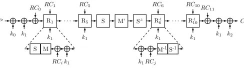
Fig. 9. Layout of PRINCE.
3) Frequent key exchange: The repeated encryptions must all use the same secret key, in order to gather consistent data for cryptanalysis. If the key is frequently exchanged, the attacker may not succeed in performing a sufficient number of encryptions using the Trojan-affected circuit to break the cipher. Moreover, if the attacker does determine the key, this key is only useful to access data that was being processed before the last key exchange. In other words, the attacker could log the encrypted data and, once the key has been determined, apply this key to decrypt these data. As soon as a new key has been generated, a new round of cryptanalysis is required. Note, however, that key distribution may be interrupted or compromised in a scenario where the attacker has physical access to the circuit. This system-level countermeasure also does not identify a Trojan but only alleviates its effect if one is present. Moreover, frequent key distribution can be costly and security is generally traded off for efficiency.
V. TROJAN FAULTATTACK ONPRINCE
In this section we describe the block cipher PRINCE, as specified in [12], report on our hardware design of the cipher, outline the fault-based cryptanalysis of PRINCE using the Multi-Stage Fault Attack algorithm [7] and explain the fault-injection techniques using the proposed MAPLE Trojans.
A. Specification of PRINCE
PRINCE is a 64-bit block cipher with a 128-bit key. Before an encryption (or decryption) is executed, a 64-bit subkey k2 is derived from the user supplied 128-bit
key k0 kk1 via k2 = (k0 ≫1)⊕(k063), where
and ≫ denote non-cyclic and cyclic shift, respectively. The subkeys k0 and k2 are used for input- and
output-whitening. The core of PRINCE is a 10-round block cipher which solely uses k1 as subkey. Figure 9 gives an
overview of the cipher.
Each round Ri and R−1j with i ∈ {1, . . . ,5} and
j ∈ {6, . . . ,10} consists of four operations: a key addition; an S-layer that applies a combinational SBoxS
shown in Figure 10a; a linear layer which multiplies the
x 0 1 2 3 4 5 6 7 8 9 A B C D E F
S[x] B F 3 2 A C 9 1 6 7 8 0 E 5 D 4
(a)
i Round constantRCi
0–2 0000000000000000,13198a2e03707344,a4093822299f31d0,
3–5 082efa98ec4e6c89,452821e638d01377,be5466cf34e90c6c,
6–8 7ef84f78fd955cb1,85840851f1ac43aa,c882d32f25323c54,
9–11 64a51195e0e3610d,d3b5a399ca0c2399,c0ac29b7c97c50dd
(b)
Fig. 10. PRINCE SBox (a), round constants (b)
state (represented by a 64-bit row vector) by a matrix
M or M0 (see the original specification [12] for the
exact definitions ofM andM0); and the addition (bitwise
XOR) of a round constant (see Figure 10b).
B. Hardware Implementation of PRINCE
We designed a combinational (fully unrolled) imple-mentation of PRINCE that executes a complete encryp-tion or decrypencryp-tion in one round, and a sequential version with one cycle per round. We implemented the circuit using Synopsys DC Compiler and Nangate Open Cell Library(45nm). The gate count and power details of the combinational version, which includes 16 identical SBoxes, are presented in Table I and shown to be highly competitive with the original circuit reported in [12]. We use this circuit for Trojan-based fault injection and cryptanalysis.
TABLE I
ASICIMPLEMENTATION DETAILS FORPRINCE (ENCRYPTION
AND DECRYPTION)
Original design Our design
Area (GE) 8260 8320
Power (mW) 38.5 41.2
C. Differential Fault Analysis of PRINCE
k1
RCi
SR-1 M’ S-1, k1
RCi+1
SR-1 M’ S-1, k1
RCi+2 r
f f ϕ(f)
0 ϕ(f) 1 ϕ(f) 2 ϕ(f) 3
r + 1
w x y z w x y z ϕ(w) 0 ϕ(w) 1 ϕ(w) 2 ϕ(w) 3 ϕ(x) 2 ϕ(x) 3 ϕ(x) 0 ϕ(x) 1 ϕ(y) 3 ϕ(y) 0 ϕ(y) 1 ϕ(y) 2 ϕ(z) 3 ϕ(z) 0 ϕ(z) 1 ϕ(z) 2
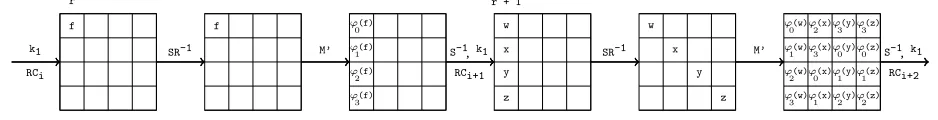
Fig. 11. Fault propagation in PRINCE over twoR−1 rounds [7]
stages are outlined below; refer to [7] for an in-depth discussion.
Stage 0 aims at restricting the keyspace for the expression (k1 ⊕ k2). The fault is injected into the
state of the cipher in the beginning of round R−19 . The general scheme of the attack does not specify the means of fault injection, but in this paper we employ the MAPLE Trojans, as described in Section V-D. The state of PRINCE is organized in 4-bit nibbles, and the attack requires that the fault injection is restricted to one nibble, that is, an arbitrary number of bits in the nibble have to be flipped, but all other nibbles must remain unaffected. Based on the obtained faulty ciphertext pair
C0 and the fault-free ciphertext C, the fault equations
are constructed as follows.
Let i ∈ {0, . . . ,15}, and let vi and vi0 be variables
representing the ith nibble of the correct and the faulty
ciphertext, respectively. Let the variables pi represent
the nibbles of the key and qi the nibbles of the round
constant RC11. The ith nibble of the state of the
fault-free circuit just before the application of the final SBox
S−1 of round R−1
10 is S(vi ⊕ pi ⊕qi). The Boolean
difference of each such nibble between the fault-free and the faulty circuit isS(vi⊕pi⊕qi)⊕S(v0i⊕pi⊕qi). On the
other hand, if the fault f is injected into the circuit state before the beginning of round R−19 , the corresponding Boolean difference of this state will be simply f. If the fault is restricted to one nibble l, it is possible to symbolically propagate the Boolean difference through round R−19 to the step in round R−110 just before SBox application. It can be shown that the value of nibble
i in that state has the shape ϕji(a) for some 4-bit value a = b0 k b1 k b2 k b3. Here, ϕji(a) is equal to a except for the jth
i bit which is set to 0 (e. g.,
ϕ2(a) = b0 k b1 k 0 k b3). The values of indices ji
are derived from the nibble l into which the fault has been injected using the propertis of the matrixM0. Their
values are shown below:
(j0, . . . , j15) =
(0,1,2,3,2,3,0,1,3,0,1,2,3,0,1,2), ifl∈ {0,7,10,13}
(3,0,1,2,1,2,3,0,2,3,0,1,2,3,0,1), ifl∈ {1,4,11,14}
(2,3,0,1,0,1,2,3,1,2,3,0,1,2,3,0), ifl∈ {2,5,8,15}
(1,2,3,0,3,0,1,2,0,1,2,3,0,1,2,3), ifl∈ {3,6,8,12}
Sixteen fault equations are obtained by propagating the Boolean difference of the observed fault-free and faulty ciphertext from the circuit outputs backward to
R10−1 and equating them with the Boolean difference f
due to the fault injection propagated forward to the same round as shown in Figure 11:
S(vi⊕pi⊕qi)⊕S(v0i⊕pi⊕qi) =
ϕji(w), i∈ {0, . . . ,3}
ϕji(x), i∈ {4, . . . ,7}
ϕji(y), i∈ {8, . . . ,11}
ϕji(z), i∈ {12, . . . ,15}
Here,w,x,yandzare unknown (free) 4-bit variables. A solution of this system of 16 fault equations contains these four variables and 16 nibbles of the secret key
p1, . . . , p16. One of the solutions is guaranteed to be the
correct secret key. The keyspace for(k1⊕k2)is restricted
from 264 possible values in the beginning by excluding
values that are inconsistent with the fault equations. This filtering is done in three steps, Evaluation, Inner FilteringandOuter Filtering; the details are omitted here and can be looked up in the Appendix (Section VIII). The size of the restricted keyspace is compared with a user-defined threshold. If the threshold is exceeded, another fault injection followed by another round of filtering is applied. Otherwise, stage 0 is finished and stage 1 starts with a set of key candidates for(k1⊕k2)
as input.
Stage 1 aims at shrinking the keyspace for k1. It
is performed similar to stage 1, with the following distinctions. The fault is injected in the beginning of roundR−18 (instead ofR−19 ) and the faulty ciphertextC0
is obtained. The analysis is repeated for each (k1⊕k2)
candidate calculated in stage 0. For each such can-didate, the last operations are “peeled off” by using
M(S(C⊕k1⊕k2⊕RC11))⊕RC10 instead of C and
M(S(C0⊕k1⊕k2⊕RC11))⊕RC10instead ofC0. Then,
the same fault equations are constructed and filtering is applied. When the keyspace falls below a user-defined threshold, brute-force search is applied for all remaining
k1 values using the k0 part of the key calculated from
(k1⊕k2). If brute-force search is unsuccessful, the guess
of (k1 ⊕k2) was wrong and stage 1 is repeated with
D. Fault Injections using MAPLE Trojans
The attack outlined in the previous section requires fault injection in single nibbles of roundsR−18 andR−19 . Faulty ciphertexts obtained from faults inR−19 (R−18 ) are used during stage 0 (stage 1) of the algorithm. As the round constants of PRINCE can be implemented through inverters, they are an ideal target for MAPLE Trojans. In order to maximize the probability of a fault injection we choose those nibbles of a round constant with a high number of inverters, namely nibble 5 from RC8 and
nibble 16 from RC9. As can be seen in Figure 10b,
these nibbles have the value d and therefore there are3 Trojan inverters for stage 0 and stage 1.
RC8 M−1 S−1
k1 c882d32f25323c54
. . .
. . .
nibble 6 nibble 5
nibble 5 nibble 4
T
T
T
regular
Trojans
Fig. 12. Trojan insertion inRC8 of PRINCE for injecting stage1
faults
The insertion of Trojan inverters into the design is illustrated in Figure 12. In the upper part the layout of round 8is depicted. The lower part shows the section of the round constants (RC8) addition at bit level, where
the MAPLE Trojans are inserted into the nibble with value d. The Trojan inverters are coloured in black and marked with a white “T”. It is important to note that faults may be injected in both stages simultaneously most of the time. However, at certain times the faults occur solely in one of the two stages. In that case we capture the resulting faulty ciphertexts and use them later for our cryptanalysis. Figure 13 shows the trigger factor of the TrojanConcinverters inserted into the combinational version of PRINCE. We observed a similar behaviour forTrojanArea inverters. The probabilities correspond to the case where the faults occur only in one of the two stages and not in both simultaneously.
E. Impact of Sequential Design
All the discussions above are for a combinational design of the PRINCE cipher, which can perform encryp-tions and decrypencryp-tions in a single clock cycle. In order
1e-05 0.0001 0.001 0.01 0.1 1 10 100
0.65 0.7 0.75 0.8 0.85 0.9 0.95
Trigger factor (%)
Vdd
Combinational design Sequential design
Fig. 13. Triggering factor of the Trojan inverters inserted into
PRINCE
to evaluate the trigger factor in a sequential design, we implemented PRINCE such that each round in the cipher takes one clock cycle, with a total of ten clock cycles for encryption and decryption. Though it takes more clock cycles, the frequency of regular operation (∼1.7 GHz) is much higher than the combinational design (∼150 MHz). As the sequential design allows an attacker to manip-ulate the supply voltage over a particular clock cycle, the number of simultaneous bit-flips can be reduced. However, to achieve higher trigger factor, the frequency must be reduced, as switching the supply voltage from one level to another takes considerable amount of time. Recent figures indicate that switching the voltage by ±0.1V takes around 20ns [17]. So, when the cipher is under attack it should be operated at a much lower frequency than the maximum frequency possible in the sequential design. Also, the sequential design does not completely eliminate the simultaneous bit-flips, albeit their likelihood is much lower (∼5%). The activation probabilities ofTrojanConcinserted in sequential design of PRINCE are shown in Figure 13.
VI. EXPERIMENTALRESULTS
In this part we report on the experimental results of the differential fault analysis of PRINCE using MAPLE Trojans. The analysis was executed on a workstation with an AMD Opteron Processor 6172 operating at 2.1GHz. The attack was executed 10000times, in each case on a data set of 50 triples (C, C0, C00) where C
MAPLE Trojans using SynopsysR NanoSimTM. Table II summarizes the results of the attack and shows that on average between 4 and 5 faults are necessary to successfully reconstruct the 128-bit key.
TABLE II
OVERVIEW ON THE NUMBER OF REQUIRED FAULTS
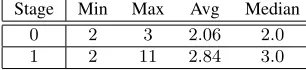
Stage Min Max Avg Median
0 2 3 2.06 2.0
1 2 11 2.84 3.0
We modified the thresholds for the Multi-Stage Fault Attack algorithm to rather low values:212for stage0and
216for stage 1. In general, higher thresholds lead to less
required fault injections but increase the complexity of subsequent post-processing. In our case, fault injections using Trojans are relatively easy to perform; therefore we opted for lower values and observed approximately one more required fault on average, compared with [7]. The run time of the post-processing algorithm, implemented in Python and employing no parallelization, was around 13 seconds.
We also analysed the distributions of the number of remaining keys after one and two fault injections and compared them to the theoretical results. The distribu-tions are shown in Figure 14. The upper graph shows the results for stage 0 and the lower graph for stage 1. The x-axis denotes the logarithms with respect to base 2 of the number of key candidates and the y-axis shows the (rounded) rate how often a particular number of key candidates occurred. There are cases where much more faults (up to 11) are required, but 2 faults were the minimum for every instance. As every exploitable fault requires a reasonable number (104−106) of fault
injections, a complete attack using 4 – 5 exploitable faults is feasible.
VII. CONCLUSION
We presented two parametric manufacturing process level Trojans and demonstrated their application to a suc-cessful fault-based attack on the state-of-the-art cipher PRINCE. The Trojans are extremely stealthy and nearly impossible to detect by today’s methods. The conducted attack is modeled by a cross-level framework which combines electrical-level simulation of an optimized PRINCE circuit with advanced post-processing based on multi-stage filtering techniques. The considered attack is particularly challenging for Trojan-based fault injection, as two fault locations in different rounds have to be used which might interfere with each other. Even with this
0 5 10 15 20 25 30 35 40 45 0
200 400600 800 1000 1200 1400
rate
1 Fault 2 Faults
0 5 10 15 20 25 30 35 40 45
log2(#keys)
0 200 400600 800 1000 1200 1400
rate
1 Fault 2 Faults
Fig. 14. Analysis results for stage0(upper) and1(lower)
restriction, the effort to inject a fault in a well-defined location is so low that the number of injected faults can be increased in order to reduce the post-processing complexity.
REFERENCES
[1] M. Tehranipoor and F. Koushanfar, “A Survey of Hardware
Trojan Taxonomy and Detection,” IEEE Design & Test of
Computers, vol. 27, no. 1, pp. 10–25, 2010.
[2] B. Cha and S. Gupta, “Trojan Detection Via Delay Measure-ments: A New Approach to Select Paths and Vectors to
Maxi-mize Effectiveness and MiniMaxi-mize Cost,” inDesign Automation
and Test in Europe, 2013, pp. 1265–1270.
[3] S. International, “Circuit Camouflage Technology - SMI IP Pro-tection and Anti-Tamper Technologies,” White Paper Version 1.9.8j, 2012.
[4] A. Barenghi, L. Breveglieri, I. Koren, and D. Naccache, “Fault Injection Attacks on Cryptographic Devices: Theory, Practice
and Countermeasures,”Proc. IEEE, vol. 99, 2012.
[5] M. Tunstall, D. Mukhopadhyay, and S. Ali, “Differential Fault Analysis of the Advanced Encryption Standard Using a Single
Fault,”LNCS, vol. 6633, pp. pp. 224–233, 2011.
[6] P. Jovanovic, M. Kreuzer, and I. Polian, “A Fault Attack on the
LED Block Cipher,” inInt’l Workshop on Constructive
Side-channel Analysis and Secure Design (LNCS 7275), 2012, pp.
120–134.
[7] P. Jovanovic, M. Kreuzer, and I. Polian, “Multi-Stage Fault Attacks on Block Ciphers,” Cryptology ePrint Archive, Report 2013/778, 2013.
[8] N. Bagheri, R. Ebrahimpour, and N. Ghaedi, “New Differential
Fault Analysis of PRESENT,”EURASIP Journal on Advances
in Signal Processing, no. 1, pp. 1–10, 2013.
[9] L. Song and L. Hu, “Differential Fault Attack on the PRINCE Block Cipher,” Cryptology ePrint Archive, Report 2013/043, 2013.
[10] H. Bar-El et al., “The Sorcerer’s Apprentice Guide to Fault
Attacks,”Proc. IEEE, vol. 94, pp. 370–382, 2006.
[11] G. Becker, F. Regazzoni, C. Paar, and W. Burleson, “Stealthy
and Embedded Systems - CHES 2013, 2013, vol. 8086, pp. 197–214.
[12] J. Borghoffet al., “PRINCE – A Low-Latency Block Cipher for
Pervasive Computing Applications,” inAdvances in Cryptology
– ASIACRYPT 2012, ser. Lecture Notes in Computer Science,
X. Wang and K. Sako, Eds. Springer Berlin Heidelberg, 2012, vol. 7658, pp. 208–225.
[13] Y. Shiyanovskii et al., “Process Reliability Based Trojans
Through NBTI and HCI Effects,” in Adaptive Hardware and
Systems (AHS), 2010 NASA/ESA Conference on, 2010, pp. 215–
222.
[14] “International technology roadmap for semiconductor (itrs),” 2006.
[15] H. Hao and E. McCluskey, “Very-Low-Voltage Testing for
Weak CMOS Logic ICs,” in Test Conference, 1993.
Proceed-ings., International, 1993, pp. 275–284.
[16] I. Polian, “Power Supply Noise: Causes, Effects, and Testing,”
ASP Jour. Low-Power Electronics, vol. 6, no. 2, pp. 326–338,
2010.
[17] W. Kim, M. S. Gupta, G.-Y. Wei, and D. M. Brooks, “Enabling On-Chip Switching Regulators for Multi-Core Processors Using
Current Staggering,” inIn Proceedings of the Work. on
Archi-tectural Support for Gigascale Integration, 2007.
VIII. APPENDIX: PRINCE KEYCANDIDATE
FILTERING
In this part we provide details on the steps done during the cryptanalysis of a correct and faulty ciphertext pair shown in Figure 11.
Evaluation. Each equation Ei is evaluated for all
possible 4-bit values u of nibble candidates associated to the variable pi. When the result of an evaluation
t = Ei(u) has been computed, the tuple (t, u) is
appended to the set Si.
Inner Filtering. In this step we check for all tuples (t, u) ∈Si if the entry t is valid with respect to the bit
pattern ϕji. Those tuples that do not have a valid entry t are discarded, all others are kept.
For example, we take fault equation E0 and assume
that a fault was injected in nibble l = 0. From the definition ofjiabove we see that the0-th entry ofj0 is0.
Moreover, we assume that the tuple (t, u) = (0x7,0x3) is an element of S0 and observe immediately that 0x7
matches the bit pattern ϕj0 = 0 k s1 k s2 k s3. Thus (0x7,0x3)is a valid tuple and0x3a potential candidate for the nibble associated to p0.
Outer Filtering. The idea in the final filtering step is to exploit the fact that the elements of the sets
S4·m, . . . , S4·m+3 are related to each other for a fixed
m∈ {0, . . . ,3}. This is due to the fact that the right-hand sides of the equations E4·m, . . . , E4·m+3 are derived
from a common pre-image. This can be utilized to build conditions for filtering candidates of the nibbles associ-ated to p4·m, . . . , p4·m+3. First we fix m ∈ {0, . . . ,3}
and order the tuples (t4·m+n, u4·m+n)∈S4·m+n
lexico-graphically for all n ∈ {0, . . . ,3}. Then we compute the sets P4·m+n containing the pre-images of all the
values t4·m+n. This is done as follows. After the Inner
Filtering, all valuest4·m+nmatch the bit pattern derived
from ϕ4·m+n. But we do not know if the j4·m+n-th bit
of t4·m+n had value 0 or 1 before it was fixed to 0.
Hence we obviously have two possible values for the pre-images oft4·m+n. One ist4·m+nitself, and the other
has a 1 at bit position j4·m+n. Then we intersect the
pre-image sets P4·m, . . . , P4·m+3 with each other and
obtain a set Gm of pre-image candidates. After that we
check for each gm ∈ Gm if, for every n ∈ {0, . . . ,3},
there is at least one tuple inS4·m+nwhich has the value
ϕi4·m+n(gm) in its first component. If so, gm is a valid pre-image. When all pre-images have been processed, all tuples are deleted from the setsS4·m, . . . , S4·m+3, except
those where the first entry has a valid pre-imagegm.
Finally, after projecting the sets Si to their second
components ui, the Cartesian product over those
projec-tions is computed to get the key candidates fork1⊕k2.
If the number of candidates fork1⊕k2 is small enough,
stage 0 of the attack ends. Otherwise the whole pro-cedure from above is executed again and the resulting candidate set is intersected with the ones from all the previous runs of the procedure. This is repeated until the set of candidates fork1⊕k2 is smaller then a previously
defined threshold τ0.
In the second stage of the attack, candidates fork1are
computed using the previously described configurations for the fault injections. This is repeated until the number of candidates for k1 falls below the specified threshold
valueτ1. As soon as this is the case, the candidates fork1
andk1⊕k2 are used to derive candidates for the subkeys
k2 andk0. Finally, a brute-force search on the Cartesian
product K0 ×K1 is performed to find the actual key
![Fig. 2.Layout of (a) original inverter and (b) Trojan inverter usingdopant polarity manipulation from [11]](https://thumb-us.123doks.com/thumbv2/123dok_us/7906606.1312776/3.612.320.556.343.514/layout-original-inverter-trojan-inverter-usingdopant-polarity-manipulation.webp)