ISSN (Print) : 2320 – 3765 ISSN (Online): 2278 – 8875
I
nternational
J
ournal of
A
dvanced
R
esearch in
E
lectrical,
E
lectronics and
I
nstrumentation
E
ngineering
(An ISO 3297: 2007 Certified Organization)
Vol. 5, Issue 7, July 2016
Modeling and Speed Control of PMBLDC
Motor Drive Using Hysteresis Current
Control for Electrically Assisted Power
Steering
K.Dileep1
PG Student [Power Electronics & Drives], Dept. of EEE, SASTRA University, Thanjavur, Tamilnadu, India1
ABSTRACT: This paper proposes an effective speed control technique with efficient control logic for the Electrically Assisted Power Steering System (EAPS) system present in automobiles. Hysteresis current control method is employed to control the speed of the Permanent Magnet Brush Less Direct Current (PMBLDC) motor drive in the power steering assembly and their results are compared. The motor is operated in forward motoring and reverse motoring modes for right and left side turn of the wheels respectively. The mathematical modeling of the PMBLDC motor drive and the speed control techniques along with the control logic are simulated in MATLAB/SIMULINK environment.
KEYWORDS:Electrically Assisted Power Steering (EAPS), Hysteresis Current Control, PMBLDC modeling.
I.INTRODUCTION
The automobile steering system offers two main functions: firstly it assists the driver to judge the driving conditions by allowing some feedback to reduce the error which the vehicle may have from the desired path and secondly, it allows the driver to follow a desired trajectory without additional effort. The EAPS systems are extremely compact, light and require low maintenance. Earlier the EAPS systems used DC Servo motor but later it was replaced with PMBLDC motor because of its advantages such as high efficiency, increased operating life, better speed versus torque characteristics and low maintenance. In an EAPS system large gear reduction ratio is not possible because it contains worm gear in the base of a steering column, so a DC-DC converter is needed to boost the PMBLDC motor’s supply voltage. Among various DC-DC converters the CUK converter is considered as beneficial because its input and output inductors provides a filtered current on both sides of the converter while the boost, buck, and buck-boost converters have a pulsating current that occurs on at least one side of the converter either input side or output side. This pulsation reduces the efficiency of the automotive battery. Hence the ripple should be reduced to ensure good efficiency. By using various controllers such PI, fuzzy logic, neural networks, etc. the duty ratio of the Cuk converter can be controlled which in turn controls the output voltage.
II. AUTOMOTIVE BATTERY
Automotive batteries are rechargeable batteries that provide electric energy for lighting, ignition, power steering systems, power windows etc. [10]. Present day automotive batteries are lead-acid type and supplies 12.6 volts of direct current. The battery actually contains six small batteries, or cells, connected in series.
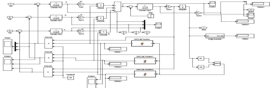
III. MATHEMATICAL MODELING OF PMBLDC MOTOR DRIVE
The basic equations for modeling a BLDC motor are as follows [1-2]: Va= Ra * Ia + Leff *dIa / dt + Ea
Vb= Rb* Ib + Leff *dIb / dt + Eb
ISSN (Print) : 2320 – 3765 ISSN (Online): 2278 – 8875
I
nternational
J
ournal of
A
dvanced
R
esearch in
E
lectrical,
E
lectronics and
I
nstrumentation
E
ngineering
(An ISO 3297: 2007 Certified Organization)
Vol. 5, Issue 7, July 2016
Ek= ∑k Ke * ɷm*fk( Ɵr )
Where,
Va,Vb,Vc- phase voltages across the stator coils
Ra,Rb,Rc- stator coil resistances
Leff - effective inductance of each stator coil
Te = ∑k Kt* Ik * fk(Ɵr)
Te = J * dɷm/ dt + B * ɷm+ Tl
dƟr/ dt = (P / 2) * ωm
Where,
Te -Electromagnetic torque
Tl - Load torque
Kt -Torque constant
J - Rotor inertia B - Damping constant
P - Number of poles Fig 1. Equivalent circuit of BLDC motor
Ɵr - Rotor position in radians
Converting time domain equations into s-domain using Laplace transform, we get I = (Va – Ea) / ( Leff * s + R )
ɷm= ( Te - Tl ) / ( J * s + B )
For Trapezoidal Back EMF consider the following equations,
ea= ɷm*λm* fas( Ɵr ) eb= ɷm*λm* fbs( Ɵr ) ec= ɷm*λm* fcs( Ɵr )
ɷm- angular speed in radians per second,
λm- Flux linkage,
ea ,eb ,ec- Back emf and fas,fbs , fcs-Trapezoidal functions based on the rotor position Ɵr.
The hall signals are generated based on the electrical angular displacement ( Ɵr ). A 3-phase PMBLDC motor has three hall sensors A, B and C located 1200 apart from each other in the stator [1-2]. The conditions when the Hall sensors should be ON / OFF are as follows,
(-600 ≤ Ɵr) AND (Ɵr ≤ 1200) = Hall A is ON ; Else Hall A is OFF ( 600 ≤ Ɵr) OR (Ɵr ≤ -1200 ) = Hall B is ON ; Else Hall B is OFF (-1800≤ Ɵr) AND (Ɵr ≤ 00) = Hall C is ON; Else Hall C is OFF
A.MATHEMATICAL MODELING OF BLDC MOTOR DRIVE
ISSN (Print) : 2320 – 3765 ISSN (Online): 2278 – 8875
I
nternational
J
ournal of
A
dvanced
R
esearch in
E
lectrical,
E
lectronics and
I
nstrumentation
E
ngineering
(An ISO 3297: 2007 Certified Organization)
Vol. 5, Issue 7, July 2016
IV. CUK CONVERTER
Cuk converter is a combination of BOOST and BUCK converter .The BOOST, BUCK and BUCK-BOOST converters uses inductive energy transfer energy between the input and the output whereas, the Cuk converter uses capacitive energy transfer [4]. Due to the small gear reduction ratio a Cuk converter is used to boost the supply voltage of the PMBLDC motor to about 48 volts from 12.6 volts DC supplied by an automotive battery. Fuzzy controller is used in the closed loop operation to maintain the output voltage [3].
Li = 2.5mH, C1 = 0.66µF, Lo = 70µH, Cd = 2200µF.
Fig 3. CUK converter
Fig 4. MATLAB model of CUK converter
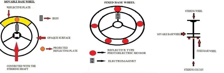
V.STEERING LOGIC
The steering logic shown in fig. 10&11 is designed based on the ON/OFF state of the reflective type photoelectric sensors. Five sensors are located on the fixed base plate as shown in fig.6 for the side turns and for the straight drive.
ISSN (Print) : 2320 – 3765 ISSN (Online): 2278 – 8875
I
nternational
J
ournal of
A
dvanced
R
esearch in
E
lectrical,
E
lectronics and
I
nstrumentation
E
ngineering
(An ISO 3297: 2007 Certified Organization)
Vol. 5, Issue 7, July 2016
Fig 8. Projected Reflecting Plate Fig 9. EAPS Model
A. SENSORS
The EAPS system shown in fig.9 contains five reflective type photoelectric sensors. A reflective type photoelectric sensor turns ON when the light emitted by it, gets reflected back by striking a reflective surface and turns OFF when the light emitted by it gets through a non-reflective surface or a translucent surface [8].
B. OPERATION
When the steering wheel is turned towards the right side, the reflective surface in the movable base plate shown in fig.5 comes above the right side photoelectric sensor so that the sensor turns ON as the emitted light gets reflected back and now the BLDC motor rotates in the clockwise direction (forward motoring) for the right side turn of the wheel, by this time the translucent surface in the movable base plate will be above the left side and the middle photoelectric sensors which in turn keeps them in OFF state.
The left side photoelectric sensor turns ON while turning the steering wheel towards left side, now the BLDC motor rotates in the anticlockwise direction (reverse motoring) for the left side turn of the wheel. The middle reflective type photoelectricsensor shown in fig.6 turns ON only when the light emitted by it gets reflected back by striking the projected reflective plate shown in fig.8 that is present in the movable base plate, it is made so by adjusting the light reflection distance setting that is present in the sensor .The output of this sensor does the following functions,
i) Turns OFF the BLDC motor,
ii) Turns ON the electromagnet to attract the iron bar located in the movable base plate to hold the steering wheel straight (with less tension) for slightly assisting the straight drive, and
iii) Resets the switching positions (S) of the left (LS) and right side (RS) sensors. C. CONFLICTOR CONDITIONS
i) WHEN RIGHT CONFLICTOR IS ‘ON’ It does two functions,
It turns OFF the right side reflective type proximity sensor and turns ON the reverse motoring mode.
ii) WHEN LEFT CONFLICTOR IS ‘ON’ It does two functions,
It turns OFF the left side reflective type proximity sensor and turns ON the forward motoring mode.
ISSN (Print) : 2320 – 3765 ISSN (Online): 2278 – 8875
I
nternational
J
ournal of
A
dvanced
R
esearch in
E
lectrical,
E
lectronics and
I
nstrumentation
E
ngineering
(An ISO 3297: 2007 Certified Organization)
Vol. 5, Issue 7, July 2016
Fig 10. Control Logic
Fig 11. MATLAB Model of Control Logic
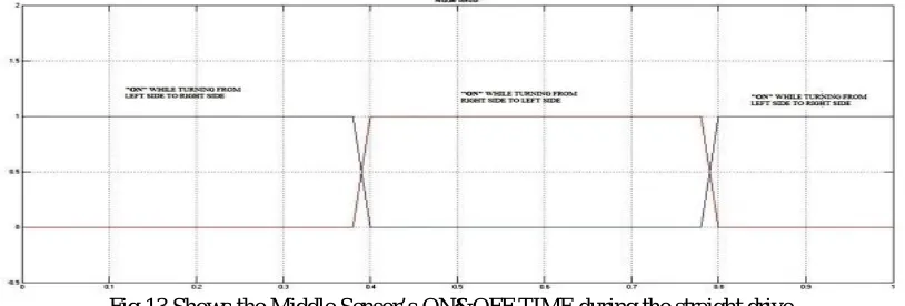
Fig 12.Shows the RS and LS SENSOR’s ON&OFF TIME for the left and right side turn of the wheels
ISSN (Print) : 2320 – 3765 ISSN (Online): 2278 – 8875
I
nternational
J
ournal of
A
dvanced
R
esearch in
E
lectrical,
E
lectronics and
I
nstrumentation
E
ngineering
(An ISO 3297: 2007 Certified Organization)
Vol. 5, Issue 7, July 2016
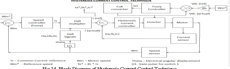
VI. HYSTERESIS CURRENT CONTROL
The Hysteresis current controller produces the gate pulses for the switches present in the VSI [7]. In this the actual current is continuously tracked within the hysteresis band and based on the band limit appropriate gate signals are produced [9]. The speed control operation of the BLDC motor for EAPS system using hysteresis current control technique is explained in the following block diagram.
Fig 14. Block Diagram of Hysteresis Current Control Technique
A. HALL MULTIPLIER
Current reference
I
ref= Tref / KTWhere, KT – Torqueconstant, andTref–Output of FUZZY controller which takes the error E (reference speed - actual speed) and its derivative dE / dt as
inputs. The Fuzzy controller has 49 rules shown in Table 1.
The hall multiplier takes the current reference Irefand the hall signals Ha , Hb and Hc as inputs to generate current
references Ia*, Ib* and Ic* for individual phases using the following equations, The MATLAB simulation of the Hall multiplier is shown in fig 15.
I
a*= I
ref* (H
c.H
a-H
c.H
a)
I
b*= I
ref* (H
a.H
b-H
a.H
b)
I
c*= I
ref* (H
b.H
c-H
b.H
c) ,
E / (dE/dt) LE LN LS Z RS RN RE
LE LE LE LE LE LN LS Z
LN LE LE LE LN LS Z RS
LS LE LE LN LS Z RS RN
Z LE LN LS Z RS RN RE
RS LN LS Z RS RN RE RE
RN LS Z RS RN RE RE RE
RE Z RS RN RE RE RE RE
Table 1. Fuzzy Rules Table
B. HYSTERESIS COMPARATOR
The current references Ia*, Ib*, Ic* and the actual phase currents Ia , Ib, Icare compared and the output is passed on to the
ISSN (Print) : 2320 – 3765 ISSN (Online): 2278 – 8875
I
nternational
J
ournal of
A
dvanced
R
esearch in
E
lectrical,
E
lectronics and
I
nstrumentation
E
ngineering
(An ISO 3297: 2007 Certified Organization)
Vol. 5, Issue 7, July 2016
Fig 15.MATLAB model of Hall Multiplier
Fig 16.MATLAB model of Hysteresis Comparator
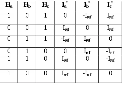
C. REFERENCE CURRENTS FOR REVERSE MOTORING
The reference currents Ia*, Ib* and Ic* for the reverse motoring mode based on the Hall sensor’s output is shown in table.
2.
Table 2. Reference currents for reverse motoring Ha Hb Hc Ia* Ib* Ic*
1 0 1 0 -Iref Iref
0 0 1 -Iref 0 Iref
0 1 1 -Iref Iref 0
0 1 0 0 Iref -Iref
1 1 0 Iref 0 -Iref
ISSN (Print) : 2320 – 3765 ISSN (Online): 2278 – 8875
I
nternational
J
ournal of
A
dvanced
R
esearch in
E
lectrical,
E
lectronics and
I
nstrumentation
E
ngineering
(An ISO 3297: 2007 Certified Organization)
Vol. 5, Issue 7, July 2016
D.MATLAB SIMULATION OF HYSTERESIS CURRENT CONTROL TECHNIQUE FOR EAPS SYSTEM
Fig 17. MATLAB model of Hysteresis Current Control technique
VII. SIMULATION RESULTS
Fig 18.shows the output voltage of the automotive battery. The automotive battery voltage is about 12.6 V.
Fig 18. Battery voltage(V) vs Time (sec)
Fig 19. shows the output voltage of the Cuk converter. The output voltage of the Cuk converter is about 48V.
ISSN (Print) : 2320 – 3765 ISSN (Online): 2278 – 8875
I
nternational
J
ournal of
A
dvanced
R
esearch in
E
lectrical,
E
lectronics and
I
nstrumentation
E
ngineering
(An ISO 3297: 2007 Certified Organization)
Vol. 5, Issue 7, July 2016
Fig 20. Shows the supply voltage Vab of the PMBLDC motor. The supply voltage of the PMBLDCmotor is 48 V.
Fig 20.Supply Voltage Vab (v) for BLDC motor drive using hysteresis current control technique
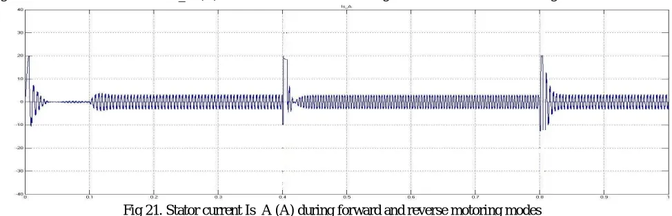
Fig 21. Shows the stator current Is_A (A) of the PMBLDC motor during forward and reverse motoring modes
Fig 21. Stator current Is_A (A) during forward and reverse motoring modes
Fig 22. Shows the Back-EMF_A of the PMBLDC motor during forward and reverse motoring modes
ISSN (Print) : 2320 – 3765 ISSN (Online): 2278 – 8875
I
nternational
J
ournal of
A
dvanced
R
esearch in
E
lectrical,
E
lectronics and
I
nstrumentation
E
ngineering
(An ISO 3297: 2007 Certified Organization)
Vol. 5, Issue 7, July 2016
Fig 23. Shows the electromagnetic torque of the PMBLDC motor during forward and reverse motoring modes
Fig 23. Electromagnetic torque Te (Nm) during forward and reverse motoring
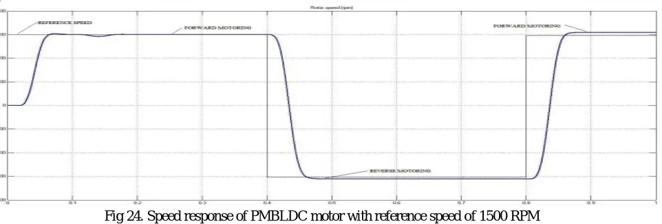
Fig 24. Shows the speed response of the PMBLDC motor drive during forward and reverse motoring modes for the set speed of 1500 RPM
Fig 24. Speed response of PMBLDC motor with reference speed of 1500 RPM
Fig 25. Shows the speed response of the PMBLDC motor drive during forward and reverse motoring modes for the set speed of 2500 RPM
ISSN (Print) : 2320 – 3765 ISSN (Online): 2278 – 8875
I
nternational
J
ournal of
A
dvanced
R
esearch in
E
lectrical,
E
lectronics and
I
nstrumentation
E
ngineering
(An ISO 3297: 2007 Certified Organization)
Vol. 5, Issue 7, July 2016
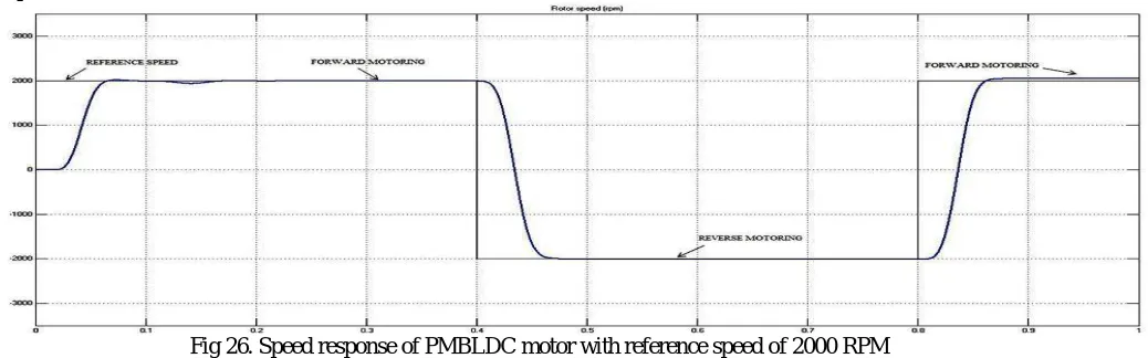
Fig 26. Shows the speed response of the PMBLDC motor drive during forward and reverse motoring modes for the set speed of 2000 RPM
Fig 26. Speed response of PMBLDC motor with reference speed of 2000 RPM
VIII. CONCLUSION
By comparing the speed curves obtained from the speed control operation of PMBLDC motor drive using hysteresis current control it is concluded that thehysteresis current control technique is best suited for an EAPS system because, when the motor changes from forward motoring to reverse motoring mode the settling time is less in hysteresis current control technique compared to other traditional techniques. So, Hysteresis current control technique provides an efficient way to control a PMBLDC motor in adjustable speed drive in an EAPS system that has quick change in loads.
REFERENCES
[1] Krishnan. R: Electric Motor Drives - Modeling, Analysis and Control: Second edition, Prentice-Hall of India Private limited, New Delhi. [2] C. C. Hwang, P. L. Li, C. T. Liu, and C. Chen, “Design and analysis of a brushless DC motor for applications in robotics,” IET Elect. Power Appl., vol. 6, Issue no. 7, pp. 385–389, Aug. 2012.
[3] K. Sakthi Priya and V. Jayalakshmi, “Simulation of Fuzzy Controller Based PFC Cuk Converter Fed BLDC Motor Drive”, International Journal of Science and Research (IJSR), Vol.no 4, Issue no. 4, April 2015.
[4] Vashist Bistand Bhim Singh “PFC Cuk Converter-Fed BLDC Motor Drive”, IEEE TRANSACTIONS ON POWER ELECTRONICS, Vol.no 30,Issue no. 2, February 2015.
[5] Z. Qun and H. Juhua, “Modeling and Simulation of the Electric Power Steering System” , Circuits, Communications and Systems, 2009. PACCS '09, Pacific-Asia IEEE Conference,Chengdu-China.
[6] C.h.Hu, “Modeling and Simulation of Automotive Electric Power Steering System” , Second International Symposium on Intelligent Information TechnologyApplication, 2008. IITA '08. Shanghai-China, Volume: 3Issue22 Dec. 2008.
[7] Norhazilina Binti Bahari ,A. b. Jidin,A. R. b. Abdullah,MdNazri bin OthmanandM. b. Manap, “Modeling and simulation of torque hysteresis controller for brushless DC motor drives”, IEEE Transactions on Industrial Informatics,Volume:9,Issue: 2, 02 October-2012.
[8] Se-Joo Kim, Yong-Ho Yoon, Kyun-Ha Jeong and Chung-Yuen Won , “A low cost position sensing method of switched reluctance motor using reflective type photo-sensors”, Industrial Electronics Society, 2004. IECON 2004, 30th Annual Conference of IEEE Volume 1, 2-6 Nov. 2004, China.
[9] H. Chen and A. M. Cramer, “Average-value modeling of hysteresis current controlled brushless DC motor drives”, Transportation Electrification Conference and Expo (ITEC), 2014 IEEE, 18 June 2014, Dearborn, MI.
[10] N. Moubayed, J. Kouta, A. El-Ali,H. DernaykaandR. Outbib, “Parameter identification of the lead-acid battery model”, Photovoltaic Specialists Conference, 2008, PVSC '08. 33rd IEEE, 16th May 2008, San Diego, CA, USA.