Performance Evaluation of Equalization Algorithms
for Electrocardiogram Signal Transmission
Priya.L*1, Kandaswamy.A#2,Danvanth.V#3,Chezhiyan.NA#4, Hariram.J# 5
1
*M. E, Assistant Professor (Sr.Gr), Department of Biomedical Engineering,
2
Ph.D, Dean, Industry Sponsored Projects and Consultancy
,
3,4,5Students, Department of Biomedical Engineering, PSG College of Technology, Coimbatore, Tamil Nadu, India
Abstract -The proposed work focuses with the performance comparison of minimizing the channel Interference for the transmission of cardiac signal over mobile n e t w o r k . Telemonitoring of Electrocardiogram (ECG) signals through mobile communication network provides unlimited coverage area, covering many patients at the same time, home-patient monitoring and provide quick diagnosis for the patient suffering from the cardiac diseases. Wireless Electrocardiogram (ECG) signal monitoring involves their timely transmission of ECG signals over high speed mobile channel poses a serious limitation to achieve high data transmission rate. The time dispersion imparted on the transmitted ECG signal results in the overlap between successive symbols known as Inter symbol Interference (ISI) causing error in ECG data at the receiver healthcare station. In this work, linear and blind equalizers are used to combat the ISI present in the frequency selective Rayleigh fading channel. This paper compares the Bit Error Rate (BER),signal to noise ratio and correlation coefficients of those equalizers for the ECG signal transmission, which are which are very suitable for telemetry applications. Results indicated that, exception of computational complexity the blind receiver performs almost as well as non blind receiver.
Keywords - ECG, ISI, Equalizers, BER, Telemetry.
I. INTRODUCTION
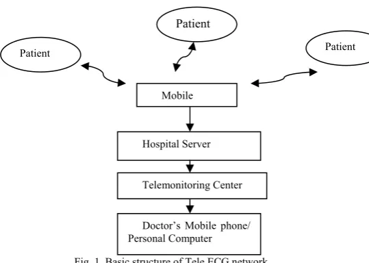
Telemetric ECG is the direct transmission of real time ECG in few minutes or few hours. The basic structure of Tele ECG network is shown in Fig.1. The tele monitoring center receives the patient ECG data in a real time, and the patients have a direct access to the doctor’s. ECGs from patients are acquired by sensor and a transmitter mounted on the human body and it is transmitted using Bluetooth/Zigbee wireless technology to the mobile phone. A real time ECG data are grouped into shorter frames and is transmitted to the tele monitoring center through the mobile network. Detailed real time ECG waveforms are displayed on the tele monitoring center. The trained experts/doctors receive patients ECG over phone; compare a transmitted ECG with the previously recorded ECG. The telemonitoring center with trained medical staff enables 24 hour monitoring of cardiac patients[1,2].
Fig. 1 Basic structure of Tele ECG network
Negoslav daja develop the new generation cellular phone with ECG recorder embedded used to monitor heart patient in a real time, the covered area of the movement of the patient is practically unlimited[3]. Kang describe the quality of service challenges for real-time ECG monitoring services in a mobile environment[4]. Ambulatory Electrocardiogram recording is now routinely used to detect infrequent, asymptomatic arrhythmias or to monitor effects of cardiac drugs or surgical procedures .With the enormously growing modern technologies, it is indeed highly probable to employ such wireless real time patient monitoring system using the technologies mentioned[5,6].
One of the major challenges for transmitting the ECG signal from patients to hospital server is that the obstruction on the transmitted way. The throughput of the wireless channel may be reduced because of multipath fading, co channel interference and noise. Intersymbol interference is the reflection of radio signals from concrete structures that results in multiple copies of the received signal which are attenuated and delayed in time. In a digital communication system, delay spread along with fading cause ISI. The main objective of the proposed work is to make sure that the ECG data at the receiver end to be error free for cardiology monitoring. Hence the utilization of channel equalizer is inevitable. The equalizer in the receiver side is the inverse modeling of the channel. Benard widrow explains the channel equalization in data modems for telephone channels, radio channels and fiber optic channels [7]. A modems adaptive filter, by adapting
Patient
Patient
Patient
Mobile
Doctor’s Mobile phone/ Personal Computer
itself to become a channel inverse, can compensate for irregularities of channel magnitude and phase using least mean square algorithm. Adaptive equalizers impulse response is the inversion of the channel filter. A zero forcing algorithm is used to reduce the channel length to mitigate the ISI effect at the receiver; this method is impractical due to the reduction of receiver throughput. Adaptive linear channel equalizer attempts to extract the transmitted symbol sequence by counteracting the effects of ISI, thereby improving the probability of correct symbol detection[8]. Since it is common for the channel characteristics to be unknown or change over time. The receiver adapts the equalizer via adaptive algorithms like least mean square, recursive least square algorithms so that its output closely matches the known reference training signal. Non linear modeling of equalizers which overcomes the classification problem of linear adaptive equalization for digital communication channel. Conventional linear and nonlinear equalization techniques which updates channel filter coefficients by supervised learning method leads to a reduction in channel capacity. The blind system is apparent where the utilization of training signals is expensive for implementation. Seedamahad developed the blind equalization algorithm for transmission frontal right lobe Electroencephalogram (EEG) signal [9, 10].The proposed method finds the solutions for the above constraints in channel equalizers by updating coefficients and compares the BER performance of different equalizers.
II. PROPOSED SYSTEM
The proposed system model is shown in Fig.2 and Fig.3.In this section, we will discuss the transmitted ECG
signal through Rayleigh channel and compare the BER performance of different adaptive equalization algorithms. Electrocardiogram (ECG) involves beat to beat recording of heartbeat in such a manner that it helps in the diagnosis of many cardiac diseases. It is the voltage-time graph recording of the electrical activity of the heart. These signals are subjected to wireless transmission for the identification of cardiovascular disease for early diagnosis and treatment. The Normal Discrete ECG signal (Lead-I) from the MIT-BIH normal sinus rhythm ECG database is used in this work. This signal is acquired from the Physionet ATM with duration of 10 seconds, sampling frequency of 128 Hz, sampling interval is 0.007825s. The maximum amplitude range for an ECG signal is -0.5 mV to 2.5 mV [11]. This discrete signal is quantized and then sends to the Quadrature phase shift keying modulator (QPSK). The phases of the two carrier waves are modulated by the two digital bit streams such as 00,01,10,11.
Design Specifications: M-ary Number: 4, Input Type: Integer, Constellation Ordering: Binary, Normalization Method: Peak Power, Peak Power referenced to 1 ohm (watts): 1, Phase offset (rad): 0, Output Data type: Inherit via back propagation.
Fig.2 ECG Transmitter Block Diagram for Base Band Communication system.
desired output
r(k) + y(k)
-
error
Fig.3 ECG Receiver Block Diagram for Base Band Communication system.
+ ECG
Source from MIT-BIH Normal sinus rhythm
Database
ECG
Quantization
Quadrature Phase shift keying
Modulator
Rayleigh frequency selective channel Interference (Hk)
Additive White Gaussian Noise w(k) s(k)
r(k)
Adaptive prediction
using FIR filter f(k) ECG Demodulator Received ECG Signal
Adaptive linear and blind equalization algorithms
A). Rayleigh Frequency selective Propagation channel model:
The QPSK signal is passed into the Rayleigh channel. The free space in this wireless system leads to addition of a number of multipath effects to the received signal; hence exact recovery of information at the receiver always is highly improbable. Rayleigh fading occurs when no Line-of-Sight (LOS) path is present between transmitter and receiver, transmitted signal gains different path length, and then the resultant signal received at the receiver will be the total of all the reflected waves. The phase of the arriving paths varies very rapidly thereby leading to rapid fluctuations in the received signal amplitude which is often modeled as random variable with a particular distribution called Rayleigh distribution. Doppler frequency is the relative motion between transmitter and receiver causes shift in the signal frequency[12,13]. The Doppler frequency is calculated by the formula
fd =(fc*v)/c ………..(1)
where fd Doppler frequency, fccarrier frequency, v
-vehicle speed, c-velocity of light
The signal bandwidth is greater than that of channel bandwidth which leads ISI in the transmitted ECG signal. This is given by Bs > Bc.
Design Specifications:
GSM: Fading type-Rayleigh; Spectral shape-Classical 6dB; Delay:3µs; Vehicle speed-84km/hr; Carrier Frequency-950 MHz; Sampling Time-3µs; Angle of Arrival-7˚; Data Rate-9.6 kbps.
The above design specifications of the Rayleigh channel model shows the good match between the model results and measurement data which is reported in for outdoor environment[14].
White Gaussian Noise(v(k)) is the white noise which has the Gaussian distribution of amplitudes that is widely present in the digital communication signals. Additive refers to the linear addition of White Gaussian noise with the transmitted signal. White noise is a random signal with constant power spectral density and Gaussian is normal distribution of amplitudes.
The receiver receives the ISI and White Gaussian noise corrupted ECG signal. It can be represented by
r[k]=s(k)+w(k)……….(2) r[k]=h(k)*s(k)+w(k)………….(3)
H). Adaptive Equalization Algorithms
The backbone of adaptive system is the adaptive linear combiner, and if the input vector Xk and the desired
response dk are available at each iteration, the adaptive
algorithms are generally the best choice for many different applications of adaptive signal processing[17]. Adaptive linear combiner was applied in two basic ways, depending on whether the input is available in parallel or serial form. In both the cases we have the combined output yk as a
linear combination of input samples. We have ek = dk –Xk.
1) LMS Algorithm:
Assume X(k) = 0 for k < 0.
Algorithm steps:
Step1: Get x[k] and d[k]
Step2: Find y[k]= deconvolve x[k] with h(k) (OR) Using vector notation: yk=xkThk ……….……..….(4)
Step3: Calculate the error e[k]=d[k]-y[k] (OR) ek=dk-yk ……….…………..(5)
Step4: Find new coefficients of the filter using steepest descent stochastic gradient estimation
h[k+1]=h[k]+2µe[k]y[k] (OR) hk+1=hk+2µekxk……… (6)
µ is the step size , 1/λmax> µ>0
λmax is the largest eigen value
Step5: Find the filter output using updated weights deconvolve x[k] with h(k+1) (OR)
yk=xkThk+1……… (7)
2)Kalman method:
Assume X(n) = 0 for n < 0.
Let hM(n) be the filter coefficient vector at time n.
Let XM(n)be the input signal vector at time n.
hM(n)=hM
(n-1)+KM(n)eM(n)……….(8)
where e(n) and eM(n) are error signals from the adaptive
filters for LMS and Kalman method respectively. KM(n)is
the Kalman gain vector.
Computation of filter output:
d^(n)=XMT(n)hM(n-1)……….(9)
where XMT(n) Transpose matrix of signal XM(n)
Computation of error:
eM(n)=d(n)-d^(n) where d(n) is the desired or reference
signal given to the adaptive filter.
Computation of Kalman gain vector:
KM(n)=(PM(n-1)XM*(n))/(w+XTM(n)PM(n-1)XM*(n))……..(10)
where PM(n) is the inverse of correlation matrix and w is
the weighting factor whose value is between 0 and 1. XM*(n) is the Hermitian autocorrelation matrix of signal
XM(n).
Adjustment rate is controlled by a single-parameter Δfor the LMS algorithm and the Kalman gain vector for KM(n)
for the Kalman method.
Kalman recursive least square Filter Algorithm : Step1: Get X[n] and d[n]
X[n] is channel output signal; d[n] is desired response Step2: Find the adaptive filter output
Y[n]=X[n]T h[n]………..………. (11)
Step3: Calculate the error
e[n]=d[n]-[n]………..…(12) Step4: Find new coefficients of the filter using Kalman
method
h[n+1]=h[n]+K[n]e[n]………..… (13) K[n] is the Kalman Gain.
3) Blind algorithm
Constant Modulus algorithm
Step1: Get x[k] and d[k]
Step2: Find y[k]= deconvolve x[k] with h(k) (OR) Using vector notation: yk=xkThk ……….….(15)
Step3:Weight updating algorithm
Wk+1=Wk-µXK(│yk│2 – 1)yk……… …..……..(16)
µ is the step size
Step 4:Computation of Gradient:
│yk│2 = yk yk = WkHxk xkHWk...(17)
Step 5:Calculate the Filter output with respect to new weights
yk = XkTWk+1
Step6: Find Error cost function
J(w)= (│yk│2 – 1) yk………(18)
III. RESULTS AND DISCUSSION
Fig.2(a) shows the source ECG signal which is downloaded from the physionet normal sinus ECG database (nsrdb/16265). This Lead 1 ECG signal is recorded for 4sec duration and its amplitude ranges from -0.5 mV to 2.5 mV. The sampling rate is 128Hz and sampling interval is 0.0078125 s. The gain of the amplifier is 200. After amplification, the ECG signal amplitude ranges from -100mv to 250mV.The simulation is averaged over 500 samples.
Fig.2(a) ECG Signal from MIT-BIH database
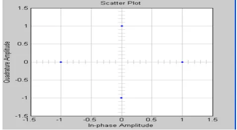
From Fig.2(b) shows the scatter plot of QPSK modulator which modulates the 4 second input ECG signal with 916 MHz carrier.
Fig.2(b) Scatter plot for Quadrature phase shift keying modulator The QPSK output signal is passed through the Rayleigh fading channel that introduce the delay spread of 3µs in urban area which is shown in Fig.2(c).
Fig.2(c) Scatter plot for Rayleigh Fading channel
Fig.2(d) shows the adaptive equalizer output which has less channel distortion and equalized with that of transmitted ECG signal.
Fig.2(d) Scatter plot for Equalizer output TABLE 1
Performance Comparison of different equalizers for ECG signal Transmission
Signal
Specification Parameters Linear equalizer method
Non linear equalizer
method Blind equalizer method
ECG Signal (MIT-BIH Database) Duration=4s Samples=500 Sampling frequency=128Hz
Bit error rate Channel Equalizer Channel Equalizer Channel Equalizer
0.48 0.051 0.48 0.02 0.48 0.1 Number of
multiplication
operations 1001 627250 4101760
Auto Correlation
coefficient 1 1 1
Cross correlation
coefficient 0.73 0.68 0.59
Table1, the linear equalizer uses Least Mean Square (LMS) algorithm is the most computationally efficient among the nonlinear algorithm. LMS multiplies operation is proportional to 2N+1 (1001) whereas nonlinear operation is proportional to 2.5N2+4.5N (627250). The least mean
square algorithm can be implemented in a practical system without squaring, averaging or differentiation and is elegant in its simplicity and efficiency. The BER of non linear equalizer outperforms with other linear and blind equalization algorithms. Correlation and signal to noise ratio results indicated that, the LMS algorithm used for the channel equalizer has better performance compared with CMA and RLS algorithms, but it requires prior knowledge about the source signal[15].
IV. CONCLUSION
In this work, we have found that under proper selection of algorithmic quantities of design, the expected behavior of CMA algorithm is identical to that of LMS and RLS algorithms. With exception of computational complexity, the CMA algorithm has superior performance than RLS and LMS algorithms. By implementing this scheme in telemetry applications, continuous monitoring of error free patient’s cardiac signal was obtained at the receiver end.
.
REFERENCES
[1]. Aris S.Lalosa c,LuisAlonso and ChristosVerikoukisb, Model based compressed sensing reconstruction algorithms for ECG telemonitoring in WBANs, Digital Signal Processing 35, 105– 116, 2014.
[2]. Kyungho Kim, A Study on a Healthcare System Using Smart Clothes, Journal of Electrical Engineering and Technology, Jan2014.
[3]. N. Daja, I. Reljin and B. Beijin, Telemonitoring in cardiology-ECG: Transmission by mobile phone, Ann. Acad. Studennica 63–66,2004.
[4]. Kyungtae Kang,An Adaptive Framework for Real-Time ECG Transmission in Mobile Environments, The Scientific World Journal, Hindawi Publishing Corporation, Volume 2014, Article ID 678309, 12 pages.
[5]. Chin-Teng Lin, An Intelligent Telecardiology System Using a Wearable and Wireless ECG to Detect Atrial Fibrillation, IEEE Transactions on Information Technology in Biomedicine, vol. 14, no. 3, May2010.
[6]. Y. Jasemian, Design and implementation of a wireless telemedicine system applying Bluetooth technology and cellular communication network: new approach for real time remote patient monitoring, PhD Thesis, Aalborg University, Denmark, 2005.
[7]. Benard widrow, Adaptive Signal Processing, Pearson Education, 2006.
[8]. Z. A. Jaffery, Adaptive Equalization of Digital Communication Channel Using Feed–Forward Neural Network, Journal of Communication and Computer, 404-409, 2011.
[9]. Seedahmed S. Mahmoud, Qiang Fang, Zahir M. Hussain, Irena Cosic, A blind equalization algorithm for biological signals transmission, Digital Signal Processing 114–123,2012.
[10]. Rashmi Baweja, Simulation of Constant Modulus Algorithm Equalizer for Human Body Communication Channel, Special Issue of International Journal of Computer Applications (0975 –8887) on Electronics, Information and Communication, Engineering - ICEICE No.6, Dec 2011.
[11]. Physiobank, Physionet, Physiologic signal archives for biomedical research, http://www.physionet.org/physiobank/, viewed Jul. 2013.
[12]. T.L. Singal, Wireless Communications, Tata McGraw Hill Education Private Limited, New Delhi, 2011.
[13]. Theodore S.Rappaport, Wirelesss Communications Priciples and Practice,Dorling Kindersley(India) Pvt.Ltd,2010.
[14]. K.I. Pedersen, P.E. Mogensen, B. Fleury, A stochastic model of the temporal and azimuthal dispersion seen at the base station in outdoor propagation environments, IEEE Trans. Veh. Technol. 49 , 437–447, Mar 2000.