Fuzzy Logic Based Controller for
Compensation of Utility Current Using
PV-Active Power Filter
M.Srujana1, M. Bala Siva Prasad2, Y.Nagaraja3
PG Student [Power Systems], Dept. of EEE, Annamacharya Institute of Technology and Sciences, Kadapa,
Andhra Pradesh, India1
Assistant Professor, Dept. of EEE, Annamacharya Institute of Technology and Sciences, Kadapa,
Andhra Pradesh, India 2,3
ABSTRACT: A three-phase three-wire system, as well as a detailed PV generator, associate degreed dc/ac voltage source convertor to act as an APF, dc/dc boost convertor to extract maximum radiation power using maximum power point tracking is presented in this paper. A source is said to be renewable if there is no obvious limit on its availability. It may be used again because it continues to replace itself. Sunshine, wind and water from rain are so renewable. Sustainable resource meets our present needs without compromising the power of future generations to satisfy their needs. The photovoltaic (PV) generation is more popular these days, while typical loads need additional high-power quality. So, one PV generator supply to nonlinear loads is desired to be integrated with a function as an active power filter (APF). The instantaneous power theory is applied to design the PV-APF controller that shows reliable performances. Here fuzzy logic is used for controlling compared to other controllers The MATLAB/Simpower Systems tool has proved that the combined system will at the same time inject maximum power from a PV unit and compensate the harmonic current drawn by nonlinear loads.
KEYWORDS: Active power filter (APF), instantaneous power theory, photovoltaic (PV), power quality, renewable energy.
I.INTRODUCTION
Now a day renewable energy resources are increasing due to power demand and decreasing of the fossil fuels. Also the requirement of power quality is very essential concern along with power quality. Today the grid-connected photovoltaic (PV) generator has become more popular because of its reliable performance and its ability to come up with power from clean energy resources. The dc output voltage of PV arrays is connected to a dc/dc boost converter using a most power point tracking (MPPT) controller to maximize their produced energy. Then, that converter is coupled to a dc/ac voltage source device (VSC) to let the PV system push electric power to the ac utility. The local load of the PV system can specifically be a nonlinear load, such as computers, compact fluorescent lamps, and plenty of different home appliances, that needs distorted currents. Development of this method is to compensate the distribution system harmonics which is equally urgent. During this case, PV generators should provide the utility with distorted compensation capability that makes currents injected/absorbed by the utility to be sinusoidal. Therefore, the harmonic compensation function is realized through flexible control of dc/ac VSC. Instantaneous power theory has successfully completed active power filter (APF) designing with good performance. However, the PV-APF combination has simply been gradually developed for several years.
The controller based on instantaneous power theory and instantaneous power balance is proposed to replace the conventional dqcurrent controller for a PV unit.
Flexible operation modes of the PV-APF combination system are possible in the proposed model. The rest of this paper is organized as follows Section II briefly introduces the implemented PV-APF combination system with the PV modeling technique and the selected MPPT topology. Section III describes the instantaneous power balance among the parts of the system mentioned in Section II. Section IV explains the proposed controller. Section V evaluates the performance of the proposed method based on simulated test cases in the MATLAB/Simpower Systems environment. Finally, the conclusion is drawn in Section VI.
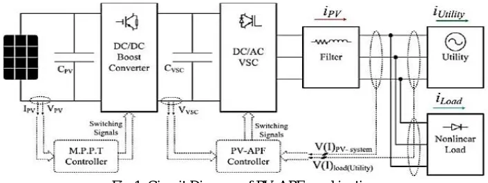
Fig 1. Circuit Diagram of PV-APF combination.
II. PV-APF COMBINATION SYSTEM
The PV-APF configuration is shown in Fig. 1, which consists of the following.
The PV 5series 66parallel array, which is Sun Power SPR 305 type, delivers a maximum of 100kW power at 1000 W/m2 solar irradiance, assuming that there is no battery energy storage system connected to the dc bus.
A 5kHz boost dc/dc converter implements MPPT by an incremental conductance integral regulator technique, that automatically varies the duty cycle so as to generate the desired voltage to extract maximum power.
The dc bus is connected to a two level three-phase dc/ac VSC with a CVSC capacitor. The dc/ac VSC converts the 500V dc to 260V/60Hz ac supplying to local nonlinear loads and connects to a stiff utility. The dq current and PV-APF and APF controllers square measure applied for this dc/ac VSC afterward.
A 10-kVAr capacitor bank filters out switching harmonics produced by the dc/ac VSC.
The loads include a three phase diode rectifier supplying a current of 450 or 50 at dc side and one phase diode rectifier with 50 dc current connecting between phase A and phase B to create an overall unbalanced load.
This PV-APF combination system is connected on to the utility for shunt active filter implementation.
A. DYNAMIC MODEL OF PV ARRAY
The PV array involves N strings of modules connected in parallel, and each string consists of M modules connected in series to get an appropriate power rating. The dynamic model of PV cell is shown in Fig. 2
A little increase in RS will decrease the PV output considerably then the 2 most significant parameters mostly used for describing the cell electrical performance are the open circuit voltage Voc= Vout + RSI obtained once the load current is zero (I = 0) and also the short-circuit current Isc. Ignoring the little diode and the ground-leakage currents below zero terminal voltage, the short-circuit current below this condition is that the photocurrent IL.
So the basic equation describing the I–V characteristic of a practical PV cell is
--- 1
where ID is the saturation current of the diode, Q is the electron charge (1.6 × 10⁻¹⁹ C), A is the curve fitting constant
(or diode emission factor), K is the Boltzmann constant (1.38×10⁻²³ J/◦K), andT (◦K) is the temperature on absolute
scale. The ISh, that, in practical cells, is smaller than IL andId, can be ignored. The diode saturation current can be determined experimentally by applying voltage Voc in the dark (IL = 0) and measuring the current entering the cell.This current is often called the dark current or the reverse diode-saturation current Id.
B. MPPT IN DC/DC CONVERTER
The cell produces the maximum power at voltage corresponding to the knee point of the IV curve, as shown in Fig. 3. Vmax and Imax are voltage and current at maximum power point, respectively. The dc/dc converter is set to operate at optimal voltage to achieve maximum power by MPPT algorithm. In this paper, switching duty cycle is optimized by the MPPT controller that uses the incremental conductance and integral regulator technique. This MPPT method is based on the fact that the power slope of the PV is null at MPP point (where dp/dv = 0), positive in the left, and negative in the right. In the following equations, dv and di are obtained by one-sample delayed values:
---2
,
--- 3
Fig 3. I–V curve and remarkable points.
III. INSTANTANEOUS POWER BALANCE
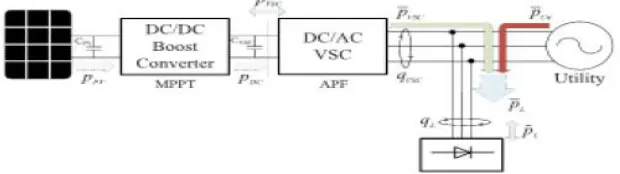
Instantaneous power flow among the components of the PV-APF system simplified in Fig. 5 may be a compromise between technical constraints and designed targets. The dc/dc boost convertor regulates its semiconductor switches to extract the utmost power generated byPV array (þPV).
The MPPT methods might be chosen appropriately in any specific circumstance beyond that convertor with the power output pDC, the dc/ac VSC keeps a major role in implementing a given control duty. At the dc side, the power idea is consistent. However, at the ac side, the instantaneous power includes both the active half (pVSC) and the imaginary part (qVSC). The losses at the dc/dc boost convertor and the dc/ac VSC are neglected.
PPV≈PDC≈PVSC. ---4
The load demand includes real power and imaginary power. In general, the real and imaginary power include two parts: 1) an average (superscript) one, and 2) an oscillating (superscript) one, which are realized through a low-pass filter (LPF) (or rarely a high-pass filter).
PVSC=P̅VSC+P̅VSC
PL=P̅L+P̅L
qL=q̅L+q̅L ---5
In this paper, the dc/ac VSC supplies harmonic and imaginary parts for the nonlinear loads (qL) in addition to the normal duty, which is to convey the active power (pVSC) from the PV unit. Different from pure linear loads that consume only average active power component, the nonlinear loads also consume the oscillating components. The APF function results in pure sinusoidal currents from the utility. Consequently, the PV-APF combination has to supply the oscillating components and one part of the average component of both real and imaginary power demand utilizing the PV output power. In general, there are two cases of utility power flow:
PV supplies enough power for local nonlinear loads and injects its excess power to the utility.
PV supplies one part of nonlinear loads consuming and the other part of load power is received from the utility.
Real power p is calculated using v, i at ac side which is the same as in dc side VPV × IPV of the PV if no loss while the imaginary power is calculated at ac side only. The average real power represents the energy flow per time in one direction only that is effectively converted into work and has to be supplied from the utility if the PV does not provide enough of this power to the load demand, while oscillating real power p represents oscillating energy flow per time. q power corresponds to conventional three phase reactive power and does not contribute to transferred power while q power is exchanged among three phases.
IV. CONTROLLERS FOR DC/AC CONVERTER
In this section, the controllers for dc/ac VSC based on instantaneous power theory and instantaneous power balance are presented. In a conventional way, the dqcurrent controller is used to inject maximum real power from PV and zero reactive power to keep unity power factor of the utility. While a nonlinear load is connected close to PV position, the proposed unique PV-APF controller should be used to compensate the harmonics and help to transfer the PV power. When there is no PV array, the APF controller is switched into the system in order to operate the CVSC capacitor just for an APF purpose.
A. PV-APF CONTROLLER
The dc/ac VSC integrated by an APF function should provide the harmonic elimination and reactive power compensation and simultaneously inject the maximum power generated by PV units. The controller is established based on the instantaneous power theory, where all the parameters are processed instantaneously. The input signals of that controller include utility voltages (vabc), nonlinear load currents (iabcL), output currents of dc/ac VSC (iabcVSC), utility injected currents (iabcUti), and dc link voltage VVSC (to prevent overcharge dc-link capacitor).
= +
Since the target is laid on the load, its consuming power is continuously measured and analyzed. Using the Clarke transformation, the instantaneous real power (pL) and imaginary power (qL) of the load can be calculated, as shown in the following equations:
= --- 7
--- 8
In general, the real and imaginary power include two parts: 1) an average (superscript) one, and 2) an oscillating one, which are realized through an LPF (or rarely a high-pass filter). The LPF cutoff frequency must be selected carefully as to the inherent dynamics of loads that lead to compensation errors during transients. Unfortunately, the unavoidable time delay of the LPF may degrade the controller performance. In practice, a fifth-order Butterworth LPF with a cutoff frequency between 20 and 100Hz has been used successfully depending on the spectral components in oscillating part that is to be compensated.
= ̅ + ̅
= ̅ + ̅ ---9
B. APF CONTROLLER
This section reminds the topology of well-known APF controllers based on instantaneous power theory. The utility currents are not measured by this controller. Only the load currents and the output currents of the APF are measured. The greatest difference of this controller compared with the PV-APF controller is the calculated reference values generated from CVSC, which are oscillating powers.
---(10)
V. FUZZY LOGIC CONTROLLER
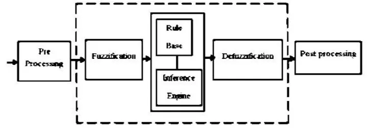
In FLC, basic control action is determined by a set of linguistic rules. These rules are determined by the system. Since the numerical variables are converted into linguistic variables, mathematical modelling of the system is not required in FC.
The FC comprises of three parts characterized as 1) seven fuzzy sets for each input and output. 2) Triangular membership functions for simplicity. 3) Fuzzification using continuous universe of discourse. 4) Implication using Mamdani’s, ‘min’ operator. 5) Defuzzification using the height method.
VI. SIMULATION VALIDATION
The systemis simulated in MATLAB/SimpowerSystems to test the PV-APF unit, which connects directly to the ac-utility, and to validate its ability to filter out the harmonic of nonlinear loads. The main parameters of the system used in the simulation study are indicated in Table 1. The simulation is run in a period of 0.75 s.
The important time instances are: 1) at 0.05 s, turn ON MPPT and VSC dqcurrent controller; 2) at 0.35 s, activate MPPT; 3) at 0.5 s, switch VCS dqcurrent controller to PV-APF controller; 4) at 0.6 s, switch to APF controller without PV; 5) at 0.7 s, switch PV-VSC out of system; and 6) at 0.75 s, stop simulation.
Fig 6. Real power from the (a) utility (b) PV unit and (c)load while the utility receives power.
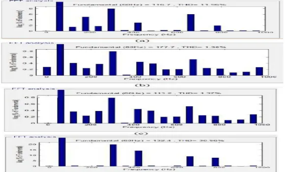
Fig 7. THD while utility receives power. (a) dq-current mode. (b) PV-APF mode. (c) APF mode. (d) Only utility supplies load.
VI. CONCLUSION
dc/ac VSC brings different current waveforms. As a result, the conventional dq-current controller should not be applied once PV is connected to a local nonlinear load regarding power-quality viewpoint.
REFERENCES
[1] L. Hassaine, E. Olias, J. Quintero, and M. Haddadi, ‘‘Digital power factor control and reactive power regulation for grid-connected photovoltaic inverter,’’ Renewable Energy, vol. 34, no. 1, pp. 315–321, 2009.
[2] N. Hamrouni, M. Jraidi, and A. Cherif, ‘‘New control strategy for 2-stage grid-connected photovoltaic power system,’’ Renewable Energy, vol. 33, no. 10, pp. 2212–2221, 2008.
[3] M. G. Villalva, J. R. Gazoli, and E. R. Filho, ‘‘Comprehensive approach to modeling and simulation of photovoltaic arrays,’’ IEEE Trans. Power Electron., vol. 24, no. 5, pp. 1198–1208, May 2009.
[4] N. R. Watson, and S. Hirsch, ‘‘Implications for distribution networks of high penetration of compact fluorescent lamps,’’ IEEE Trans. Power Del., vol. 24, no. 3, pp. 1521–1528, Jul. 2009.
[5] I. Houssamo, F. Locment, and M. Sechilariu, ‘‘Experimental analysis of impact of MPPT methods on energy efficiency for photovoltaic power systems,’’ Int. J. Elect. Power Energy Syst., vol. 46, pp. 98–107, Mar. 2013.
[6] M. A. G. de Brito, L. P. Sampaio, G. Luigi, G. A. e Melo, and C. A. Canesin, ‘‘Comparative analysis of MPPT techniques for PV applications,’’ in Proc. Int. Conf. Clean Elect. Power (ICCEP), Jun. 2011, pp. 99–104