c e-ISSN: 2348-6848, p- ISSN: 2348-795X Volume 3, Issue 01, January 2016
International Journal of Research (IJR)
Available at http://internationaljournalofresearch.orgAn Advanced Speed Control Scheme for IPM Based
Synchronous Generator
R.Jaga n Babu
1& S.Raj Shekar
21
M.Tech Scholar, Dept. of EEE, ASR College of Engineering and Technology, JNTUK, A.P
2
Assistant Professor, Dept. of EEE, ASR College of Engineering and Technology, JNTUK, A.P
Abstract:
This paper proposes a direct control strategy for
an interior permanent magnet synchronous
generator-based variable speed wind turbine by
using fuzzy logic. In this scheme, the requirement
of the continuous rotor position is eliminated as
all the calculations are done in the stator
reference
frame.
This
scheme
possesses
advantages such as lesser parameter dependence
and reduced number of controllers compared with
the traditional indirect vector control scheme.
Fuzzy logic adds to bivalent logic an important
capability—a capability to reason precisely with
imperfect information. Imperfect information is
information which in one or more respects is
imprecise, uncertain, incomplete, unreliable,
vague or partially true. In fuzzy logic, results of
reasoning are expected to be provably valid, or
p-valid for short. The direct control scheme is
simpler and can eliminate some of the drawbacks
of traditional indirect vector control scheme. The
proposed control scheme is implemented in
MATLAB/ Sim Power Systems and the results
show that the controller can operate under
constant and varying wind speeds. Finally, a
sensor less speed estimator is implemented, which
enables the wind turbine to operate without the
mechanical speed sensor. The simulation and
experimental results for the sensor-less speed
estimator are presented.
Keywords:
Direct control; interior permanent
magnet (IPM) synchronous generator; sensor-less
speed estimator; variable speed wind turbine;
Fuzzy logic Controller
I.
I
NTRODUCTION
The wind energy will play a major role to
meet the renewable energy target worldwide, to
reduce the dependency on fossil fuel, and to
minimize the impact of climate change. Currently,
variable speed wind turbine technologies
dominate the world market share due to their
advantages over fixed speed generation such as
increased energy capture, operation at maximum
power point, improved efficiency, and power
quality [1]. This technology has an advantage of
having power electronic converter with reduced
power rating (30% of full rated power) as the
converter is connected to the rotor circuit.
However, the use of gearbox in these turbines to
couple the generator with the turbine causes
problems.
Variable speed wind turbine using permanent
magnet synchronous generator (PMSG) without
gearbox can enhance the performance of the wind
energy conversion system. The use of permanent
magnet in the rotor of the PMSG makes it
unnecessary to supply magnetizing current
through the stator for constant airgapflux.
Therefore, it can operate at higher power factor
and efficiency [5], [6]. The previous works done
on PMSG based wind turbines are mostly based
on surface permanent magnet-type synchronous
generator [7] [9]. Very few works have been done
so far on interior PMSG based wind turbines,
which can produce additional power by exploiting
their rotor saliency [10]. It can also be operated
over a wide speed range (more than rated speed)
by flux weakening, which will allow constant
power-like operation at speeds higher than the
rated speed [10], [11]. This work is based on
interior permanent magnet-type synchronous
generator-based variable speed wind turbine.
c e-ISSN: 2348-6848, p- ISSN: 2348-795X Volume 3, Issue 01, January 2016
International Journal of Research (IJR)
Available at http://internationaljournalofresearch.orglogic is fuzzy. The stated definition underscores
that fuzzy logic is precise. In fuzzy logic precision
is achieved through association of fuzzy sets with
membership functions and, more generally,
association
of
granules
with
generalized
constraints [11]. What this implies is that fuzzy
logic is what may be called precisiated logic.
Moreover, this scheme introduces high
voltage surge on the generator winding which can
reduce the life span of the generator [16].
Traditional vector control scheme, as shown in
Fig. 1, is widely used in modern PMSG-based
variable speed wind energy conversion system
[6], [10], [11], [15]. In this scheme, the generator
torque is controlled indirectly through current
control. The output of the speed controller
generates the - and – axes current references,
which are in the rotor reference frame. The
generator developed torque is controlled by
regulating the currents and according to the
generator torque equation. For high performance,
the current control is normally executed at the
rotor reference frame, which rotates with the
rotor. In this paper, a direct control strategy is
implemented where coordinate transformations
are not required as all the calculations are done in
stator reference frame. Thus, the requirement of
continuous rotor position is eliminated.
Fig. 1. Traditional vector control scheme for the IPM synchronous generator
II. PROPOSED TOPOLOGY –IPM
SYNCHRONOUS GENERATOR MODEL&
PROPOSED CONTROLLING
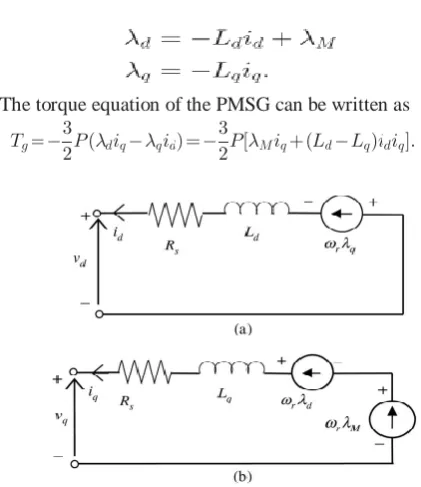
The machine model in reference frame, which is synchronously rotating with the rotor, where -axis is aligned with the magnet axis and axis is orthogonal to - axis, is usually used for analyzing the interior permanent magnet (IPM) synchronous machine [13]. The - and – axes voltages of PMSG can be given by
The - and -axes flux linkages are given by
The torque equation of the PMSG can be written as
Fig. 2. dq-model of IPM synchronous generator: (a) -axis equivalent circuit and (b) --axis equivalent circuit.
Fig. 3.Proposed direct control scheme for the IPM generator side converter.
c e-ISSN: 2348-6848, p- ISSN: 2348-795X Volume 3, Issue 01, January 2016
International Journal of Research (IJR)
Available at http://internationaljournalofresearch.orgThe first term in the torque equation (11) is the excitation torque that is produced by the interaction of permanent magnetflux and and is independent of. The second term is the reluctance torque that is proportional to the product of and and to the difference between and . For the surface PMSG, the reluctance torque is zero since , while for the IPM synchronous generator, higher torque can be induced for the same and ,if( ) is larger. This is one of the advantages of IPM synchronous generator over surface PMSG.
III. PROPOSED TOPOLOGY –DIRECT
CONTROL SCHEME FOR IPM SYNCHRONOUS GENERATOR The direct control scheme for IPM synchronous generator is shown in Fig. 3. In this scheme, current controllers are not used. Instead, the flux linkage and torque are controlled directly. The torque and flux are controlled using two hysteresis controllers and by selecting optimum converter switching modes, as shown in Fig. 3. The selection rule is made to restrict the torque and flux linkage errors within the respective torque and flux hysteresis bands to achieve the desired torque response and flux linkage [10]. The required switching-voltage vectors can be selected by using a switching voltage vector lookup table, as shown in Table I. The selection of the voltage space vectors can be determined by the position of the stator flux linkage vector and the outputs of the two hysteresis comparators. The hysteresis control blocks compare the torque and flux references with estimated torque and flux, respectively. When the estimated torque/flux drops below its differential hysteresis limit, the torque/flux status output goes high. When the estimated torque/ flux rises above differential hysteresis limit, the torque/flux output goes low. The differential limits, switching points for both torque and flux, are determined by the hysteresis bandwidth [11], [12]. The appropriate stator voltage vector can be selected by using the switching logic to satisfy both the torque and flux status outputs. There are six voltage vectors and two zero voltage vectors that a voltage source converter can produce. The combination of the hysteresis control block (torque and flux comparators) and the switching
logic block eliminates the need for a traditional PW modulator [10].
The optimal switching logic is based on the mathematical spatial relationships of stator flux, rotor flux, stator current, and stator voltage. These relationships are shown in Fig.4 as rotor reference, stator flux reference, and stationary reference frames. The angle between the stator and rotor flux linkages is the load angle if the stator resistance is neglected. In the steady state, is constant corresponding to a load torque and both stator and rotor fluxes rotate at the synchronous speed. In the transient operation, varies and the stator and rotor fluxes rotate at different speeds. The magnitude of the stator flux is normally kept as constant as possible, and the torque is controlled by varying the angle between the stator flux vector and the rotor flux vector [10].
Table.1 . SIX-VECTOR SWITCHING TABLE FOR CONVERTER
c e-ISSN: 2348-6848, p- ISSN: 2348-795X Volume 3, Issue 01, January 2016
International Journal of Research (IJR)
Available at http://internationaljournalofresearch.orgIV. PROPOSED TOPOLOGY –CONTROL OF
STATOR FLUX LINKAGE BY SELECTING PROPER STATOR VOLTAGE VECTOR
The stator voltage vector for a three-phase machine with balanced sinusoidally distributed stator windings is defined by the following equation:
where the phase axis is taken as the reference position and are the instantaneous values of line to neutral voltages. In Fig.5, the ideal bidirectional switches represent the power switches with their antiparallel diodes. The primary voltages and are determined by the status of these three switches . Therefore, there are six nonzero voltage vectors and and two zero voltage vectors and . The six nonzero voltage vectors are 60 apart from each other, as in Fig.6. These eight voltage vectors can be expressed as
Fig. 5. Rectifier connected to IPM synchronous generator.
Fig. 6. Available stator voltage vectors
How far the tip of the statorflux linkage will move is determined by the duration of time for which the stator vector is applied. In Fig. 7, the voltage vector plane is divided into six regions – to select the voltage vectors for controlling the amplitude of the stator flux linkage. In each region, two adjacent voltage vectors are selected to keep the
switching frequency minimum. Two voltages may be selected to increase or decrease the amplitude of. For instance, voltage vectors and are selected to increase or decrease the amplitude of, respectively, when is in region and the statorflux vector is rotating in counter clockwise direction. In this way, the amplitude of can be controlled at the required value by selecting the proper voltage vectors. How the voltage vectors are selected for keeping within a hysteresis band is shown in Fig. 8 for a counter clockwise direction of. The hysteresis band here is the difference in radii of the two circles in Fig. 7. To reverse the rotational direction of, voltage vectors in the opposite direction should be selected.
Fig. 7. Control of the amplitude of stator flux linkage
c e-ISSN: 2348-6848, p- ISSN: 2348-795X Volume 3, Issue 01, January 2016
International Journal of Research (IJR)
Available at http://internationaljournalofresearch.orgThe angle decreases and torque decreases too. By selecting the voltage vectors in this way, is rotated all the time and its rotational direction is determined by the output of the hysteresis controller for the torque [6], [8].The six-vector switching table for controlling both the amplitude and rotating direction of is shown in Table I and is used for both the directions of operations. In Table I, and are the outputs of the hysteresis controllers for flux linkage and torque, respectively. If , then the actual flux linkage is smaller than the reference value. The same is true for the torque. – are the region numbers for the stator flux linkage positions.
V. MATLAB BASED SIMULATION &RESULTS
DISCUSSION
The direct control scheme for IPM synchronous
generator based variable speed wind turbine shown in Fig. 3 is implemented in MATLAB/ Sim Power Systems dynamic system simulation software. The IPM synchronous generator data are given in Table III. Table I is used for switching the converter. The bandwidths of torque and flux hysteresis controllers are 10% of their rated values.
Fig.8. MATLAB based simulation diagram of proposed system with masked blocks
Fig.9. MATLAB based simulation diagram of traditional
system FFL block
Fig.10. Shows the MATLAB based simulation of the traditional control scheme responses- wind speed
Fig.10. MATLAB based simulation of the proposed control scheme responses-wind speed
Fig.11. Shows the MATLAB based simulation of the traditional control waveform q-axis current and its reference
Fig.11. MATLAB based simulation of the traditional control waveform- waveform q-axis current and its
reference
Fig12. Shows the MATLAB based simulation of the traditional control scheme- d-axis current and its reference
c e-ISSN: 2348-6848, p- ISSN: 2348-795X Volume 3, Issue 01, January 2016
International Journal of Research (IJR)
Available at http://internationaljournalofresearch.orgFig.13. MATLAB based simulation of the traditional control scheme - speed reference and measured speed.
Fig.14. Shows the MATLAB based simulation of the proposed control scheme – wind speed
Fig.14. MATLAB based simulation of the proposed control scheme – wind speed
.
Fig.15. Shows the MATLAB based simulation of the proposed control scheme - torque and its reference
Fig.15. MATLAB based simulation of the proposed control scheme - torque and
its reference
Fig.16. Shows the MATLAB based simulation of the proposed control scheme – flux linkage and its reference
Fig.16. MATLAB based simulation of the proposed control scheme – flux linkage and its reference
Fig.16. Shows the MATLAB based simulation of the proposed control scheme – speed reference and measured.
Fig.16. MATLAB based simulation of the proposed control scheme – speed reference and
measured.
TABLE.II.SIMULATION SPECIFICATIONS
CONCLUSION
c e-ISSN: 2348-6848, p- ISSN: 2348-795X Volume 3, Issue 01, January 2016
International Journal of Research (IJR)
Available at http://internationaljournalofresearch.orgdependence; 2) torque and flux control without rotor position and PI controller which reduce the associated delay in the controllers; and 3) sensor less operation without mechanical sensor. The results show that the direct controller can operate under varying wind speeds. However, direct control scheme has the problem of higher torque ripple that can introduce speed ripples and dynamic vibration in the power train. The methods to minimize the torque/ speed ripples need to be addressed. The simulation and experimental results for the sensorless speed estimator are presented, and the results show that the estimator can estimate the generator speed quite well with a very small error.
R
EFERENCES[1] S. Müller, M. Deicke, and R. W. D. De Doncker,“Doubly fed induction generator system for wind turbines,”IEEE Ind. Appl. Mag., vol. 8, no. 3, pp. 26–33, May 2002.
[2] J. Hu, H. Nian, H. Xu, and Y. He,“Dynamic modeling and improved control of DFIG under distorted grid voltage conditions,”IEEE Trans. Energy Convers., vol. 26, no. 1, pp. 163–175, Mar. 2011.
[3] M. Mohseni, M. S. M. Islam, and M. A. Masoum,“Enhanced hysteresisbased current regulators in vector control of DFIG wind turbine,”IEEE Trans. Power Electron., vol. 26, no. 1, pp. 223–234, Jan. 2011.
[4] T. F. Chan and L. L. Lai, “Permanent-magnet machines for distributed generation: A review,”IEEE Power Engg. Annual Meeting, Tampa, FL, USA, Jun. 24–28, 2007, pp. 1–6.
[5] M. E. Haque, M. Negnevitsky, and K. M. Muttaqi,“A novel control strategy for a variable-speed wind turbine with a permanent magnet synchronous generator,” IEEE Trans. Ind. Appl., vol. 46, no. 1, pp. 331–339, Jan./Feb. 2010.
[6] R. Esmali and L. Xu,“Sensorless control of permanent magnet generator in wind turbine application,”IEEE Industry Applications Society Annual Meeting, Tampa, FL, USA, Oct. 8–12, 2006, pp. 2070– 2075.
[7] Z. Q. Zhu and J. H. Leong, “Analysis and mitigation of torsional vibration of PM brushless ac/dc drives with direct torque controller,” IEEE Trans. Ind. Appl., vol. 48, no. 4, pp. 1296–1305, Jul./Aug. 2012.
[8] H. Zhu, X. Xiao, and Y. Li, “Torque ripple reduction of the torque predictive control scheme for permanent-magnet synchronous motors,” IEEE Trans. Ind. Electron., vol. 59, no. 2, pp. 871–877, Feb. 2012.
[9] P. C. Krause, O. Wasynczuk, and S. D. Sudhoff, Analysis of Electrical Machinery and Drive System. Piscataway, NJ, USA: IEEE Press, 2002
[10] M. E. Haque, M. Negnevitsky, and K. M. Muttaqi, “A novel control strategy for a variable-speed wind turbine with a permanent magnet synchronous generator,” IEEE Trans. Ind. Appl., vol. 46, no. 1, pp. 331–339, Jan./Feb. 2010.
[11] S. Zhang, K. J. Tseng, D. M. Vilathgamuwa, T. D. Nguyen, and X. Y. Wang, “Design of a robust grid interface system for PMSG-based wind turbine generators,” IEEE Trans. Ind. Electron., vol. 58, no. 1, pp. 316–328, Jan. 2011.
[12] K. Nishida, T. Ahmed, and M. Nakaoka, “A cost-effective high-efficiency power conditioner with simple MPPT control algorithm for wind-power grid integration,” IEEE Trans. Ind. Appl., vol. 47, no. 2, pp. 893–900, Mar. 2011.
[13] C. N. Bhende, S. Mishra, and S. G. Malla, “Permanent magnet synchronous generator based standalone wind energy supply system,” IEEE Trans. Sustain. Energy, vol. 2, no. 4, pp. 361–373, Oct. 2011.
[14] S. M. R. Kazmi, H. Goto, H. J. Guo, and O. Ichinokura, “A novel algorithm for fast and efficient speed-sensorless maximum power point tracking in wind energy conversion systems,” IEEE Trans. Ind.
Electron., vol. 58,