Wind to Hydrogen for Energy Storage
Sarun Kumar K P1, Dr. Devi V2
PG Student [Power Electronics], NSS College of Engineering, Palakkad, Kerala, India1
Professor, Dept. of EEE, NSS College of Engineering, Palakkad, Kerala, India 2
ABSTRACT: Due to the intermittency of the renewable energy sources, the involvement of power electronics controllers became more important for managing a regulated output. Advanced power electronic systems, affordable high performance devices, and smart energy management principles are deemed to be an integral part of renewable, green and efficient energy systems. A combination system for wind power generation and hydrogen generation is proposed which has a Doubly-Fed Synchronous Generator (DFSG) and an electrolyser which comprises of electrodes and water to form hydrogen. Thus wind energy is converted to hydrogen, which is an energy carrier and that can be stored. This paper presents a combination system through a cooperative control between wind generator output and electrolyser unit. The produced hydrogen is stored in a tank made of material called air-stable magnesium nano-composites. This composite material consists of ‘nano-particles of magnesium metal sprinkled through a matrix of polymethyl methacrylate – a polymer related to Plexiglas’. The stored hydrogen can be used as fuel in rockets and in fuel cell vehicles. Recently it has been used in hydrogen powered Tram developed by China.
KEYWORDS: Doubly Fed Synchronous Generator, Wind Turbine Generation System, Hydrogen.
I. INTRODUCTION
We now live in a truly global society. In the highly automated industrial front with economic competitiveness, two technologies will dominate in future which are the Computer and Power Electronics. The Computer provides intelligence as to “what to do” and Power Electronics gives “the means to do it”. Power electronics is the technology associated with efficient conversion and control of electric power by power semiconductor devices. And the goal of power electronics is to control the flow of energy from electric source to electric field.
The utility electricity sector in India had an installed capacity of 305.55 GW as of 31st August 2016, in that renewable power plants constituted 28% of total installed capacity. We are bound to use energy very efficiently by improving conversion efficiency and by increasing the energy production from renewable sources. Using highly efficient power electronics in power generation, power transmission/distribution and end user application, together with advanced control solutions makes the way for renewable energies. The most emerging renewable energies, e.g. wind energy and photovoltaic, which by means of power electronics can achieve a major part in electricity generation. Among different renewable energies, wind energy has achieved the fastest growth in the world. The total wind power capacity as on 30th June 2016 in India was 27,151 MW. The scenario always pushes the India market for wind technology into a more competitive area.
II. NEED FOR HYDROGEN GENERATION
Now a days, hydrogen came up as an alternative energy to oil, due to the problems of global warming and dwindling fossil fuel supplies. Hydrogen can be produced by various methods including thermolysis in nuclear reactors and reforming of natural gas. Hydrogen is widely used in household fuel cells, but most of this hydrogen is obtained from reforming natural gas, which does not resolve the problem of carbon dioxide emissions and dwindling fossil fuel supplies. Thus, methods using the electrolysis of water are regarded as effective for clean hydrogen generation because fossil fuels are not used as a source material. However, electric power is required in order to generate hydrogen by the electrolysis of water. Supplying that power from petroleum or from other forms of thermal power generation does not help to solve the problem of dwindling fossil fuels or CO2 emissions in a fundamental manner. Thus, wind power
generation and other forms of hydrogen generation using renewable energy have become important.
However, renewable energy is usually variable, and represents an unstable power source for the electric power grid. In wind power generation, the output fluctuates significantly because of its dependence on fluctuations in wind speed, and as a result there are concerns about adverse effects on the connected power grid as the capacity of installed wind turbine generators increases. A secondary battery or other power storage device is generally used to smooth the wind power generation output. However, storing power for the long term is difficult, and the costs of high capacity power storage devices for this purpose are high. Thus, systems that combine wind power generation and an electrolyzer for water as a hydrogen generation device have been proposed. Smoothing of wind power output is possible by using the fluctuations for hydrogen generation with an electrolyzer. Also, because of the need to store electric power as hydrogen, energy storage over the long term can be achieved by using tanks to store the hydrogen. A part of the output power is fed to the electrolyzer, rest of the power is smoothed and fed to the grid by the proposed control system. Hydrogen generator should be operated as ON/OFF condition as partial loading has a negative influence in their service life. The proposed control system also avoids frequent switching of the electrolyzers and maintains the average duty cycle for each electrolyzer, i.e. operation period of each electrolyzer has been tried to keep near the average utilization.
III. MODEL SYSTEM ANALYSIS
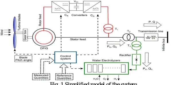
The model system used for this study is shown in the Fig.1. This system contains a variable speed wind generator, which is a 10MW Doubly Fed Induction Generator (DFIG). The hydrogen generator in the wind turbine generation system does not produce hydrogen only but also contributes in smoothing the output power. In order to achieve this control scheme, the reference value for the output to the power system and the number of active electrolyzers are very important. As the output from the wind generator changes randomly depending on stochastic wind speed, the mean value and the standard deviation has been used here to separate the generator output in the smoothing part and fluctuating part. This has been used as the reference power to be consumed by the electrolyzers.
IV. ELECTROLYZER MODEL AND SWITCHING STRATEGY
Fig. 2 Hydrogen Generator Circuit
The Fig. 2, shows the hydrogen generation device model. Step-down choppers are attached to the electrolyzers, divided into six blocks, and the terminal voltage of each electrolyzer is controlled independently by connecting them in parallel. The operation of the chopper in steady state consists of only two possibilities: ON operation, which applies the rated voltage in order to generate hydrogen in the electrolyzer, and OFF operation, which does not generate hydrogen. There will be three blocks like Fig. 2. And by controlling the ON/OFF operation in each block, the overall power consumption of the hydrogen generation device can be controlled by varying the number of blocks included in the system. Table 1 lists the characteristics of the hydrogen generation device for one block.
In addition to switching the electrolyzer blocks individually ON and OFF, control is also applied to smoothen the final active time for each electrolyzer block and the number of instances of ON/OFF switching. If the length of the active time and the number of instances of ON/OFF switching are assumed to be proportional to the degradation of the electrolyzer block, this is not desirable from the standpoint of device maintenance. Thus, the smoothing described above can be achieved by shifting the operating electrolyzers in sequence. This approach is applied, using the rule that the electrolyzer that is ON is shifted in sequence when the electrolyzer block is ON, and switching OFF starts from the first unit that is ON when the block is OFF.
Table 1. Parameters of Hydrogen generators
Rated capacity of one block 0.66 [MW]
Rated voltage V 1612.5 [V]
Internal resistance R0 0.5 [Ω]
Internal voltage V0 1407.5 [V]
Reactor L0 10 [mH]
Capacitor C0 500 [µF]
Reactor L 10 [mH]
Fig. 3 Operation Shift
Fig. 3 gives the operation shift for the electrolyzers. In accordance with the rule described above, when increasing power consumption, the electrolyzer block is turned ON in the sequence (1), (2) (*I); when decreasing power consumption it turns OFF (1), the first to be turned ON (*II), and when increasing power consumption again, it turns the electrolyzers ON in sequence (*III). By repeating this procedure, the active times for the electrolyzers are smoothed, and the number of instances of ON/OFF switching can also be smoothed.
V. ELECTROLYZER USED
Now we have the wind's energy delivered in a useful form to the electrolyzer. An electrolyzer has one main goal, to take in water and electricity and produce hydrogen and oxygen. Here we use Proton Energy Systems HOGEN 40RE proton exchange membrane as electrolyzers. Hydrogen H-Series generators utilize Proton Exchange Membrane (PEM) cell stack and Pressure Swing Adsorption (PSA) technology to produce ultra-high purity hydrogen for various applications, some of which include materials processing, generator cooling and semiconductor fabrication, etc. These systems benefit hydrogen users by improving supply reliability and site safety, while also reduces hydrogen storage space. The generators are modular, field-upgradeable and designed to compete with delivered hydrogen anywhere in the world. A single H6 unit will supply the equivalent of one and one-half jumbo tube trailers every
month. Multiple H-systems may be combined for additional capacity at no extra integration cost. The main features of the electrolyser are , auto fill water level control, water monitoring system including purity monitor, automatic production control, system senses demand and adjusts production rate and purge airflow monitoring system assures safe operation and automatic leak detection system.
VI. HYDROGEN COMPRESSOR
Like air compressors found in mechanics workshops, our system compresses the hydrogen gas that's coming out of the electrolyzers from 150 pounds per square inch to a maximum pressure of 3,500 pounds per square inch. The higher pressure allows more hydrogen to be stored in the tanks.
VII. H2 STORAGE
Hydrogen is a cleaner renewable energy source but only the problems is safe storage. The traditional way of fastening hydrogen into solids has not been very successful. Too less volume of hydrogen was absorbed while storing and too convoluted methods like too high heating or cooling was needed for releasing it which did not make it commercially viable.
capable of absorbing and releasing hydrogen at an ordinary temperature without oxidizing the metal. This capacity has been touted as the major step towards a better design for hydrogen storage, hydrogen batteries and hydrogen fuel cells. The scientists have been able to design successfully the composite materials that are nano-scale and are capable of
overcoming the barriers that are thermodynamic and kinetic in nature. Hydrogen is as safe, natural gas and gasoline.
There are some excellent qualities of hydrogen that make hydrogen safer, like the fact that it is 14 times lighter than air and disperses very well in the case of a leak. On the other hand, hydrogen has a much wider flammability range (4-74) in air than other fuels we are used to. All things considered, hydrogen can be as safe as the other fuels mentioned.
VIII. ADVANTAGES OF USING HYDROGEN
Hydrogen is just one of the options that are getting quite a bit of attention. The energy that is created is then stored in hydrogen storage tank, which can be later used for power generation. Hydrogen energy is being considered one of the most plausible and applicable choices for alternative energy, simply because of the abundance of it that we have on this planet. The advantage of using hydrogen as an energy source is because of its abundance in nature. There is no worry about running out of hydrogen anytime soon, unlike fossil fuels and other non renewable resources. All of the energy sources that we are currently utilizing are harmful and toxic, not only for humans and animals, but for our environment as well. Hydrogen fuel cells are completely non toxic and pose no risk to our climate. Along with being renewable and non toxic, hydrogen fuel cells are also incredibly powerful. They are so powerful that they are used as fuel in rockets into space by NASA recently. There are no green house gas emissions that are associated with hydrogen fuel cells. These gasses, which are released by other types of non renewable resources, are the cause of global warming and a massive climate change. While the initial costs may be a bit high, once they are installed, hydrogen fuel cells are very affordable to maintain. This same idea would go if cars began running on hydrogen energy.
IX. PROPOSED DESIGN
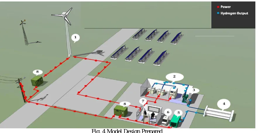
Fig. 4 Model Design Prepared
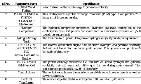
Table 2. Component specification
Sl.No. Equipment Name Specification
1 100 kW Wind Turbine
Wind turbine use the wind energy to generate electricity.
2 PROTON ENERGY SYSTEM HOGEN 40RE
Electrolyzer
This electrolyzer is a proton exchange membrane (PEM) type. It can produce 2.27 kilogram of hydrogen per day.
3 Hydrogen Compressor
The hydrogen compressor compresses hydrogen gas that's coming out of the electrolyzers from 150 pounds per square inch to a maximum pressure of 3,500 pounds per square inch.
4 Hydrogen Storage Tank
The tank can store up to 85 kilogram of hydrogen at 3,500 pounds per square inch.
5 HYDROGEN
ENGINE CENTER. INC Internal Combustion
Engine
The internal combustion engine runs on stored hydrogen and generate electricity that will sent to grid for use during peak demand. This generator can produce 60 kilowatts of electricity.
6 PLUG POWER PEM Fuel Cell
The proton exchange membrane fuel cell runs on stored hydrogen and generate electricity that will send onto utility grid for use during peak demand. This generator can produce 5 kilowatts of electricity.
7 Control Room The control room houses the monitoring and data collection equipments as well as power electronics.
8 Electrical Transformer
This device steps the electrical voltage from 480 volts to 13,200 volts.
X. CONCLUSION
Here the proposed system, simultaneously smoothens the grid output and generates hydrogen for energy storage by combining a hydrogen generation device and a doubly fed adjustable speed wind generator. It generally takes around 50 – 55 kWh of electricity to produce 1 kg of hydrogen. It roughly requires another 10 kWh to compress the gas (to 875 bar) and dispense it in to Fuel Cell Electric Vehicle (FCEV), if you are looking at hydrogen as a transportation fuel. Ideally, it takes 39.4 kWh of electricity and this is known as the Higher Heating Value (HHV) of hydrogen. We use the HHV when dealing with low temperature (< 100C) water electrolysis. In the case of high temperature systems where the heat might be ‘free’ we might use the Lower Heating Value (LHV) of hydrogen which is 33.3 kWh/kg. Due to the electrode deterioration in the electrolyzer, and because providing fluctuating power is not desirable, operation was set to involve only two points, an ON state and an OFF state, using the power control device. The power consumed in the hydrogen generation device was made adjustable by varying the number of electrolyzer blocks in the ON state. The system was created so that the grid output was smoothed by having an adjustable wind turbine generator absorbing a small portion of the fluctuations, including the effect of turning the electrolyzers ON and OFF.
REFERENCES
[1] Mobasseer M. Hossain, M.R.I. Sheikh, Md. Shamsur Rahman PK, “Cooperatively Controlling of Grid Connected DFIG Based Wind Turbine
with Hydrogen Generation System”, 1stInternational Conference on Electrical and Electronics Engineering ,Nov.2015 IEEE.
[2] Rion Takahashi, Yuusuke Otsuki, Junji Tamura, Masatoshi Sugimasa , Akiyoshi Komura, Motoo Futami, Masaya Ichinose, Kazumasa Ide, “A
New Wind Generation System Cooperatively Controlled with Hydrogen Electrolyzer”, XIX International Conference on Electrical Machines - ICEM 2010, Rome, 2010 IEEE.
[5] S. M. Shinde, K. D. Patil, Ms. S. S. Khairnar and W. Z. Gandhare, “The Role of Power Electronics in Renewable Energy Systems Research and Development”, IEEE Trans. Power Electronics, pp.726 - 730, Nov. 2009.
[6] Satyendra Vishwakarma, K. B. Mohd. Umar Ansari, Goldy Sharma, “Importance of Power Electronics in Renewable Energy System”, ISSN:
0975 – 6736, Vol. -02, no. – 02, pp.301 – 306.
[7] P. Ledesma and J. Usaola, “Doubly Fed Induction Generator Model for Transient Stability Analysis”, IEEE Trans. on Energy Conversion,
Vol.20, No.2, pp.388-397, 2005.
[8] T. Sun, Z. Chen, and F. Blaabjerg, “Transient Stability of DFIG Wind Turbines at an External Short-Circuit Fault”, Wind Energy, Vol.8,
No.3,pp.345-360, 2005.
[9] R. Chen et al., “Toward Secure Distributed Spectrum Sensing in Cognitive Radio Networks,” IEEE Commun. Mag., vol. 46, pp. 50–55, Apr.
2008.
[10] H. Khalife, N. Malouch, S. Fdida, “Multihop cognitive radio networks: to route or not to route,” IEEE Network, vol. 23, no. 4, pp. 20-25,
2009.
[11] Y.-C. Liang et al., “Sensing-Throughput Trade-off for Cognitive Radio Networks, ”IEEE Trans. Wireless Commun., vol. 7, pp. 1326–37
,April 2008.
[12] P. K. Visscher, “How Self-Organization Evolves,” Nature, vol. 421, pp. 799–800 Feb.2003.
[13] D.P. Kothari, K. C. Singal, Rrakesh Ranjan, “Renewable Energy Sources and Emerging Technologies”, Second Edition,PHI Learning Pvt.