A New Approach to Direct Torque Control of
Induction Motor with Teaching Learning
Based Optimization
A.Gopi 1, MD.Shameem2, V.Srilatha3
Assistant Professor, Dept. of EEE, Amrita Sai Institute of Science and Technology, Andhra Pradesh, India Assistant Professor, Dept. of EEE, Amrita Sai Institute of Science and Technology, Andhra Pradesh, India Assistant Professor, Dept. of EEE, Amrita Sai Institute of Science and Technology, Andhra Pradesh, India
ABSTRACT: The undesired torque and flux ripple may occur in conventional direct torque control(DTC) induction motor drive. DTC can improve the system performance at low speeds by continuously tuning the regulator by adjusting the Kp, Ki values. In thisTeaching Learning Based Optimization(TLBO ) is proposed to adjust the parameters (Kp, Ki) of the speed controller in order to minimize torque ripple, flux ripple, and stator current distortion.The TLBO based PI controller has resulted is maintaining a constant speed of the motor irrespective of the load torque fluctuations.
KEYWORDS: Teaching Learning Based Optimization, Direct Torque Control, PI controller.
I. INTRODUCTION
Induction motors are the most widely used machines in AC drives because of their rugged construction and cost . To control the torque and flux of the induction motor different strategies are available as per the literature. Direct torque control is one of the methods which is used in variable frequency drives for the control of the induction motor. Direct torque control has emerged over the last decade to become one possible alternative to the well-known Vector Control of Induction Machines. In DTC, the stator flux and the torque are directly controlled by selecting the appropriate inverter state. The output of the speed regulator (PI controller) results in generation of the reference torque. However the PI controller cannot result in perfect control if its parameters Kp, Ki are not properly chosen. The undesired torque and flux ripple may occur in conventional direct torque controlled induction motor drive. DTC can improve the system performance at low speeds by continuously tuning the regulator by adjusting the Kp, Ki values. Many artificial intelligence techniques and random search methods have been employed to improve the control parameters.
II. MATHEMATICAL MODELING OF INDUCTION MOTOR
Mathematical modelling of the induction motor been done based on the equations (1) – (5).
q s s q s q s
d s s d s d s
r q r q r r d r
d
V = R i + φ (1 )
d t d
V = R i + φ (2)
d t d
0 = R i + φ ω φ (3
d t
r d r d r r q r
e d s q s q s d s
)
d
0 = R i + φ ω φ (4 )
d t
3 p
T = (φ i φ i ) (5 )
2 2
III. CONVENTIONAL DIRECT TORQUE CONTROL
A. DTC STRATEGY:
Field Oriented method decouples stator current vector into d-q components. FOC duplicate the DC motor dynamics. Unlike FOC, DTC does not duplicate the DC motor dynamics, but DTC method chooses the voltage vectors according to the demanded flux and torque in order to keep them within hysteresis bands.
The torque developed by the induction motor is given by
m
e s r
s r
3 p
L
T =
λ λ sinθ (6)
2 2
σL L
From the above equation we can say that the torque produced by the induction motor depends upon the stator flux, rotor flux and phase angle between them.
The induction motor stator voltage equation is given by
s s s
d
λ
V =
- I r (7)
dt
s
Change in flux can be expressed as
s s
Δλ = V t
(8)
proposed. The most famous, which is frequently used in industrial applications, is the Ziegler-Nichols method which does not require a system model and control parameters are designed from the plant step response. Tuning using this method is
Fig 1.Conventional DTC of Induction motor.
characterized by a good disturbance rejection but on the other hand, the step response has a large percentage overshoot in addition to a high control signal that is required for the adequate performance of the system. Another technique uses frequency response methods to design and tune PI controller gains based on specified phase and gain margins as well as crossover frequency. Furthermore, root locus and pole assignment design techniques are also proposed in addition to transient response specifications. All these methods are considered as model based strategies and then the efficiency of the tuning law depends on the accuracy of the proposed model as well as the assumed conditions with respect to actual operating conditions. All these techniques takes a more time fortuning the PI controller.To overcome the stated problems, an adaptive PI controller has been proposed to replace the classical PI controller where the proportional and integrator gains are tuned by the Differential Evolution algorithm.
IV.TEACHING LEARNING BASED OPTIMIZATION
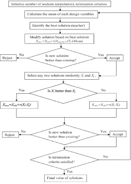
FLOWCHART OF TLBO ALGORITHM
Fig. Flow chart of TLBO algorithm
STEPS IN TEACHING AND LEARNING BASED OPTIMIZATION ALGORITHM
The main steps involved in TLBO algorithm are as follows:
A. INITIALIZATION
(4.1)
Where p = population size
D = no. of variables
B. TEACHER PHASE
Calculate the mean of the population column-wise, which will give the mean for the particular subject as
D 1 2 D
M, = [m ,m , . . . m ]
(4.2)The best solution will act as teacher for that phase
Teacher f (x) min
X
X
(4.3)The teacher will try to shift the mean from M,D towards
X
Teacher, which will act as a new mean for the iteration. So,,D teacher ,D
M _ new
X
(4.4) The difference between two means is expressed as,D ,D F ,D
Difference
r(M_new
T M )
(4.5)The value of TF is selected as 1 or 2. The obtained difference is added to the current solution to update its values using
new ,D old ,D ,D
X
X
Difference
(4.6)Accept
X
new if it gives better function valueC. LEARNER PHASE
As explained above, learners increase their knowledge with the help of their mutual interaction. The mathematical expression is
n
i j
i j
new,i old,i i i j
new,i old,i i j i
new
For i
P
Randomly select two learnersX and X where i
j
if f(X )<f(X )
X
X
r (X
X )
Else
X
X
r (X
X )
End If
End For
Accept X
if it gives a better function value.
1,1 1,2 1,D
2,1 2,2 2,D
,1 ,2 ,D
. . .
. . .
Population =
. . .
n n n
P P P
x
x
x
x
x
x
0 0.5 1 1.5 2 2.5 3 3.5 0
5 10 15 20
time(sec)
L
o
ad
t
o
rq
u
e(
N
-m
)
0 0.5 1 1.5 2 2.5 3 -10
-5 0 5 10
time(sec)
L
o
ad
t
o
rq
u
e(
N
-m
)
5 10
e
(N
-m
)
D. SELECTION
By sorting the profits, the nests with the best profit values are selected and memorize the best solution and go to step 2.
E.STOPPING CRITERIA
Step 3 is repeated until the minimum or maximum (depends on minimization or maximization) is achieved or maximum iteration count is reached.
In the current work, when the number of generations reaches the given maximum number of generations is used as stopping criteria. Best nests are copied to next generations until stopping criteria is satisfied.
Results and Discussions
FromTLBO Program we obtained the optimized values, that values substitute in the DTC system and finally observed results of TLBO based DTC system at different load torques. The applied load torques and the motor speed wave forms of TLBO based DTC with Conventional DTC shown in the 4(a), 5(a), 6(a), 7(a) and 4(b), 5(b), 6(b), 7(b) respectively.
Fig.4(a) Applied load torque Fig.4(b).Speed wave forms of conventional and TLBO based DTC
0 1 2 3 4 -10
-5 0 5 10
time(sec)
L
o
ad
to
rq
u
e(
N
-m
)
Fig.7(a).Applied load torque. Fig.7(b).Speed waveforms of Conventional and TLBO based DTC.
VI. CONCLUSION
Based on the DTC induction motor, TLBO tuned PI controller is proposed in this paper.TLBO tuned PI controller also improves the speed adjustment capability of the DTC system. From the simulation results of TLBO based DTC it has been observed that an improved torque and flux response was achieved. The command flux optimization scheme has reduced the torque ripple. It can be concluded that TLBO based DTC is better compared to the conventional DTC system
.
REFERENCES
[1] Abou El Ela AA, Abido MA, Spea SR. “Optimal power flow using differential evolution algorithm,” Electr Power Syst Res, Vol.80, pp.878–85, 2010.
[2] K. Ohyama, G. M. Asher, and M. Sumner, “Comparative analysis of Experimental Performance and stability of sensorless induction motor Drives,” IEEE Trans. Ind. Electron.Vol. 53, no. 1, pp. 178–186, Feb. 2006.
[3] Nadia Salvator Andrea Caponio, Student, FerranteNeri, Silvio Stasi, and Giuseppe Leonardo Cascella, “Optimization of Delayed- State Kalman-
Filter- Based Algorithm via Differential Evolution for SensorlessControl of Induction Motors” IEEE transactions on Industrial Electronics, Vol. 57, No. 1,
January 2010.
[4] C.Thanga Raj, member, IAENG,S.P.Srinivastava,andpramodAgarwal “Differential Evolution Based optimal control of Induction Motor By Serving tom Textile Industry,” IAENG International Journal of Computer Science, 35:2, IJCS-35-2-03.
[5] K. V. Price, “Differential evolution: A practical approach to global optimization,” Springer, Berlin, 2005.
[6] Fang Wang, YuhuiQiu, “A modified particle swarm optimizer with Roulette selection Operator,” IEEE conference proceedings of NLP-KE, 2005, pp. 765- 768.
[7] Hassan FarhanRashag,S.P.Koh ,Ahmed N.Abdalla,NadiaM.L.Tan,K.H.Chong and S.K.Tiong.”DTC torque ripples minimization based on PSO-PID controller” Scientific Research and Essays Vol. 7(15), pp.1572,23,April,20
[8] H. M. B. Metwally, f. E. Abdul-Kader, H. M. El-Shewy, M. M.El-Kholy, “Proposed torque Optimized behavior for digital speed Control of induction motor,” Energy Conversion and Management, Vl. 43, 2006, pp. 1675-1685.
[9] Price, K.V., Storn, R.: Differential evolution – A simple evolution strategy for fast optimization. Dr. Dobb’s Journal 22(4) (1997) 18–24.