© 2015, IRJET.NET- All Rights Reserved
Page 429
Design and Development of ON-LINE UPS using PIC Microcontroller
1
Hemal Patel,
2Divyesh Vaghela
1
Hemal Patel, M.Tech Student, Institute of technology, Nirma University, Ahmedabad, India.
2
Divyesh Vaghela, Assistant Professor, Institute of Technology, Nirma University Ahmedabad, India.
---***---Abstract:
The proposed ON-Line uninterruptible power supply (UPS) offers AC voltage regulation on continuity basis which incorporates with the controllable battery charger. The battery used is Lead Acid Type battery. The charge control technique used for battery is constant current charging technique. The Constant Current is achieved by limiting the duty cycle of charger (or step-down chopper). In proposed scheme, protection of battery over charge and battery under discharge is available with relay trip through PIC 16F877A microcontroller by monitoring voltages on continues basis. The backup of battery takes place the load without spikes or delay when the mains power gets fails or interrupted. Based upon the proposed constant current charging technique, a digital charger is designed and is control through PIC 16F877A microcontroller software. The inverter used is simple square wave inverter. Experimental results using PIC 16F877A microcontroller controlled battery charger cum rectifier is presented to shows the effectiveness of the proposed design.Key Word
s
: UPS - Uninterruptible Power Supply, PIC - Peripheral Interface Controller, LCD - Liquid Crystal Display switch. When the AC main is available, the rectifier circuit will supply the power to the inverter as well as to the battery and battery will be charged. If the supply power fails suddenly, the battery will supply power to the inverter without any interruption and delay. If the UPS fails (inverter fails), then the main static switch is turned-on which automatically transfers the ac line to the load. Figure 1 shows the block diagram of on-line UPS.This paper proposes a new topology for ON-Line UPS. The proposed system, consist of battery charger cum rectifier which is controllable through PIC microcontroller.
Therefore, the battery management will and precise monitoring will be done.
Fig -1: Block Diagram of ON-Line UPS
2. The Proposed Topology:
© 2015, IRJET.NET- All Rights Reserved
Page 430
Power supply+ Transformer
Rectifier With filter
Step-down Chopper
Relay Battery Inverter Load
Power Supply
PIC Microcontroller AC
MAINS AC
MAINS
Fig 2: Block Diagram of Proposed Topology
3. Circuit Diagram Consideration for Battery Charger:
© 2015, IRJET.NET- All Rights Reserved
Page 431
230 AC voltages are applied to the step down transformer of 0-18 V/ 8 A. The output of 18 V ac is converted into 12 V dc through rectifier. Rectifier with filter capacitor converts AC into 12 V DC. The capacitors of 2200 µF/ 50 V are used be different. The inductor used is toroidal type.
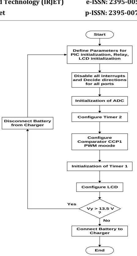
The variable DC is fed to the battery through the resistors of 12 kΩ and 3 kΩ. The voltage sample Vx is taken between 12 kΩ and 3 kΩ resistor. Also, other voltage sample Vy is taken across the battery. The voltage samples Vx and Vy are given to the PIC microcontroller for comparing purpose for constant current charging of battery. When the voltage sample Vy is less than 14 V, the load relay will be turns off, and when the voltage sample Vy is more than 12 V, the load relay will be turns on. Also, when voltage sample Vy is more than 14 V it will increases the duty cycle of step down chopper and when voltage sample Vy is less than 14 V it will decreases the duty cycle of step down chopper.
The output from pin 17 of port C is given to pin 3 of the level shifter CD4504. At pin 1 of CD4504 the supply of +5 V is fed. Also, the capacitors of 100 uf / 16 V and 0.1 uf are connected for high and low frequency input noise suppuration. The level shifter shifts voltages from +5 V to +12 V (low to high). The output from level shifter CD4504 is fed to pin 10 of MOSFET driver IR2110. The output from pin 7 through the current limiting resistor of 100 Ω is given to the gate terminal of MOSFET.
There are four different conditions:
1. Mains available and Battery fully charged at that time
Charger to Battery Relay will be Off and Battery to Load Relay will be On.
Also, Vl to be regulated equal to Vb so that battery will not discharge.
2. Mains available and Battery not fully Charged
Charger to Battery Relay will be On and Battery to Load Relay will be On.
Charging to be regulated so as to keep Ib < 1 A 3. Mains fail and Battery not fully charged but not
discharged
Charger to Battery Relay will be Off and Battery to Load Relay will be On.
4. Mains fail and Battery Discharged
Charger to Battery Relay will be Off and Battery to Load Relay will be Off.
4.
Circuit Diagram consideration for Inverter:
The push-pull configuration of inverter is used for designing of inverter for ON-Line UPS. For switching operation MOSFET Switches IRFP150 are used. For that MOSFET switches MOSFET driver IR2110 is used. The output from pin 33 and 34 as PWM waveforms are fed to pin 5 and pin 7 of the level shifter CD4504. The level shifter shifts voltages from +5 V to +12 V (low to high). The 12 V output from level shifter CD4504 is fed to pin 10 and pin 12 of MOSFET driver IR2110. The power supply for MOSFET driver IR2110 is connected at pin 6 which is as shown in Figure 4.
© 2015, IRJET.NET- All Rights Reserved
Page 432
Fig 4: Circuit Diagram of Inverter5.
Flowchart
Consideration
for
PIC
Programming:
© 2015, IRJET.NET- All Rights Reserved
Page 433
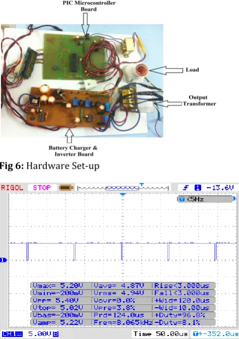
Fig 6: Hardware Set-upFig 7: Switching Waveforms of Battery Charger: Switching Frequency: 8kHz
Fig 8: Switching Waveforms of inverter: Switching Frequency: 50Hz
Fig 9: Output Current and Voltage waveforms: Output Voltage: 200V
The output current and voltage are in phase as shown in Figure 10.
Fig 10: Output Current and Voltage waveforms with phase continuity
7.
Conclusion:
© 2015, IRJET.NET- All Rights Reserved
Page 434
8.
REFERENCES:
[1] Farrukh Kamran and Thomas G. Habetler, “A Novel On-Line UPS with Universal Filtering Capabilities” IEEE TRANSACTIONS ON POWER ELECTRONICS, VOL. 13, NO. 3, MAY 1998.
[2] L. Bowen, R. Zarr, S. Denton, National Semiconductor Corporation, “A Microcontroller Controlled Battery Fuel Gauge and Charger”, 1994 IEEE.
[3] Stephen P. Sacarisen, Jahangir (J.P.) Parvereshi, “Improved Lead-Acid Battery Management Techniques” Benchmark Microelectronics.
[4] Shri Karve, “UPS of three kind", IEE Review March, 2000.
[5] Nasser H. Kutkut,Herman L. N. Wiegman, Deepak M. Divan and Donald W.Novotny, “Design Considerations for Charge Equalization of an Electric Vehicle Battery System” IEEE Transactions On Industry Applications, VOL. 35,NO. 1, January/February 1999.
[6] Ankur Bhattacharjee, “Design and Comparative Study of Three Photovoltaic Battery Charge Control Algorithms
in MATLAB/SIMULINK Environment” International
Journal of Advanced Computer Research, Volume-2
Number-3 Issue-5 September, 2012.
[7] M.Z.U. Khan and C.D. Manning “Microprocessor
Controlled Inverter for Ups Applications” Louthborough University of Technology, U.K.
[8] M. Zafarullah Khan and Cnrlton Dudley Manning, “A HIGH QUALITY MICRO - PROCESSOR CONTROLLED ULTRASONIC PWM INVERTER FOR UPS APPLICATIONS", Loughborough University of Technology, Lough-
Borough, U.K.