Volume 2010, Article ID 169132,12pages doi:10.1155/2010/169132
Research Article
A Study on Event-Driven TDMA Protocol for
Wireless Sensor Networks
Haigang Gong,
1Ming Liu,
1Guihai Chen,
2and Xue Zhang
11School of Computer Science and Engineering, University of Electronic Science and Technology of China, Chengdu 6 10054, China 2Deparment of Computer Science and Engineering, Shanghai Jiaotong University, Shanghai 200242, China
Correspondence should be addressed to Haigang Gong,[email protected]
Received 14 February 2010; Accepted 3 November 2010
Academic Editor: Xiang-Yang Li
Copyright © 2010 Haigang Gong et al. This is an open access article distributed under the Creative Commons Attribution License, which permits unrestricted use, distribution, and reproduction in any medium, provided the original work is properly cited.
MAC protocol controls the activity of wireless radio of sensor nodes directly so that it is the major consumer of sensor energy and the energy efficiency of MAC protocol makes a strong impact on the network performance. TDMA-based MAC protocol is inherently collision-free and can rule out idle listening since nodes know when to transmit. However, conventional TDMA protocol is not suitable for event-driven applications. In this paper, we present ED-TDMA, an event-driven TDMA protocol for wireless sensor networks. Then we conduct extensive simulations to compare it with other MAC protocols such as BMA, S-MAC, and LMAC. Simulation results show that ED-TDMA performs better for event-driven application in wireless sensor networks with high-density deployment and under low traffic.
1. Introduction
Like in all other shared-medium networks, medium access control (MAC) is also a key component to ensure the successful operation of wireless sensor networks. A MAC protocol decides when competing nodes could access the shared medium and tries to ensure that no collisions occur while nodes’ transmission. Compared to nodes in traditional wireless networks, the main constraint of sensor nodes in WSNs is their low finite battery energy. Since sensor nodes are often powered by battery and left unattended after deployment, for example, in hostile or hash environments,
making it difficult to replace or recharge their batteries,
MAC protocols running on WSN must consume
energy-efficiently in order to achieve a longer network lifetime.
According to Estrin et al. [1], the radio component of sensor nodes consumes most of nodes’ energy when receiving or transmitting data, even in idle mode. On the other hand, medium access control (MAC) protocol directly controls the activity of nodes’ radio and decides when the competing nodes may access the shared medium to transmit the data. So, medium access is the major consumer of nodes’ energy and MAC protocols must be energy-efficient.
When running a MAC protocol, much energy is wasted
due to the following sources of overhead: (a)Idle listening:
since a node does not know when it will be the receiver of a message from one of its neighbors, it must keep its
radio in idle listening mode at all times. (b) Collisions: if
two nodes transmit at the same time and interfere with each other, collisions happen and packets are corrupted. (c)
Overhearing: a node may receive packets that are not destined for it. In fact, it would have been more efficient to turn offits
radio. (d)Protocol overhead: the MAC headers and control
packets used for signaling do not contain application data and are therefore considered overhead.
MAC protocols designed for wireless sensor network can be broadly divided into schedule-based and
contention-based protocols [2]. Schedule-based MAC protocols,
includ-ing TDMA, FDMA and CDMA, have a central point permitting the access to the shared medium by broadcasting a schedule that specifies when each node may transmit over the shared medium. The lack of contention overhead
guarantees that the method robust when traffic load is
high. Furthermore, with the proper scheduling, nodes can get deterministic access to the medium and can provide delay-bounded services. For contention-based MAC
they must handle the possible collisions while data trans-mission. Contention-based MAC protocols may deal with collisions through some contention resolution scheme such as retransmitting the data later or occupying the shared medium before data transmission. Compared with schedule-based MAC protocols, contention-schedule-based MAC protocols consume more energy because they waste energy in collisions and idle listening. Moreover, they do not give delay guaran-tees. However, they are very flexible and can handle the traffic fluctuations in wireless sensor networks.
In schedule-based MAC protocols, TDMA is more power efficient because it is inherently collision-free and can avoid unnecessary idle listening. For example, the TDMA protocol
for a traffic-monitoring network described in [6] has a
lifetime of 1,200 days compared with ten days using the IEEE 802.11 protocol. For the inherently property of energy conserving, TDMA protocols have been recently attracted significant attention for many applications [7–10].
However, TDMA only applies for continuous monitoring applications, that is, continuous collecting the temperature or humidity of the environments. They could achieve high channel utility because sensor nodes always have data to send in continuous data gathering applications. But when applying for another typical application in WSNs-event-driven applications such as earthquake monitoring or target tracking, in which sensor nodes only have data to send when a specific event occurs, they will waste more energy and achieve lower channel utility for that sensor nodes still must be active when the event does not happen.
In this paper, we present ED-TDMA, an event-driven TDMA protocol for wireless sensor networks. And extensive simulations are conducted to compare it with other MAC
protocol such as BMA [10], S-MAC and LMAC [11] in
different scenarios. Simulation results show that ED-TDMA
performs better for wireless sensor network with
high-density deployment and low traffic.
The rest of the paper is organized as follows. Section 2
discusses some typical MAC protocols. Section 3 presents
the problem and system model.Section 4describes our
ED-TDMA protocol in detail and analyzes its energy
consump-tion. Simulation results are discussed in Section 5. Finally,
Section 6concludes the paper.
2. Related Works
2.1. Contention-Based MAC Protocols. Sensor-MAC
(S-MAC) protocol [4] is a contention-based effective MAC
protocol designed by Ye et al. for wireless sensor networks The basic idea of S-MAC is that time is divided into large
frames. Every frame starts offwith a small synchronization
phase, followed by a fixed active part and a sleep part. During synchronization phase, nodes receive or send SYNC packet contained the schedule information (i.e., when to sleep).
During the sleep part, a node turns offits radio to preserve
energy. During the active part, it can communicate with its neighbors and send any messages queued during the sleep part. Since all messages are packed into the active part,
instead of the whole frame, therefore the energy wasted on idle listening is reduced.
Timeout-MAC (T-MAC) protocol [5] introduces an
adaptive duty cycle too. In T-MAC, a node keeps listening and potentially transmitting as long as it is in an active period. If a node does not detect any activity within the time-out interval, it can safely assume that no neighbor wants to communicate with it and goes to sleep. The activation time events include reception of any data, the sensing of communication on the radio, and so forth. Simulations
show that T-MAC gives better results under different loads.
However, T-MAC breaks the synchronization of the listen periods, and introduces early sleep problem which is harmful to the network performance.
TA-MAC [12] modifies the contention window
mech-anism of S-MAC. It adjusts the initial contention window
according to the current traffic load to reduce the collision
probability and employs a fast back-off scheme to reduce
the time for idle listening during back-offprocedure, which
reducing the energy consumption. Simulation results have shown that TA-MAC achieves energy savings and higher
throughput when traffic load is heavy.
2.2. Schedule-Based MAC Protocols. In schedule-based MAC protocols, TDMA is inherently collision-free and can avoid unnecessary idle listening. The main task in TDMA schedul-ing is to allocate time slots dependschedul-ing on the network topology and the node packet generation rates. A proper schedule not only avoids collisions by silencing the interferers of every receiver node in each time slot but also minimizes the number of time slots hence the latency. TDMA pro-tocols could be categorized into cluster-based TDMA and distributed TDMA. The former are for networks in which the nodes are organized into several clusters, and cluster heads allocate time slots to their members. Distributed TDMA is more challenging than cluster-based TDMA because spatial reuse of a time slot may be possible. More than one node can transmit at the same time slot if their receivers are at nonconflicting parts of the network.
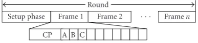
BMA protocol is a cluster-based protocol which improves traditional TDMA schedule in that there exists a contention phase (CP) in the beginning of each TDMA frame. In the contention phase during each frame, source nodes send 1-bit message to their cluster heads to reserve time slot so that cluster heads know which members will transmit in this frame and allocate successive time slot to these source nodes. When the source nodes finish their transmission, cluster heads could be asleep and will be active in the next frame. While saving energy for sleeping after transmission, BMA introduces extra schedule overheads for its TDMA scheduling. Moreover, it achieves poor channel utility for event-driven applications.
C A B
Setup phase Schedule Frame 1 Frame 2 · · · Framen
Round
Figure1: Frame structure of traditional TDMA protocol.
LMAC [11] is a typical distributed TDMA protocol.
Nodes organize time into slots, grouped into fixed-length frames. A slot consists of a traffic control section and a fixed-length data section. The scheduling discipline is extremely simple: each active node is in control of a slot. When a node wants to send a packet, it broadcasts a message header in the control section detailing the destination and length until its time-slot comes around, and then immediately proceeds with transmitting the data. Nodes listening to the control header turn offtheir radio during the data part if they are not an intended receiver of the message. However, nodes must always listen to the control sections of all slots in a frame, even if the slots are unused.
TRAMA protocol [13] is another distributed TDMA
protocol. Nodes periodically exchange their information and learn their two-hop neighborhood. Based on this knowledge, nodes periodically reserve future slots for backlogged traffic. A hash-based priority scheme is then used so that only one node in a two-hop neighborhood will transmit in a given slot. Unfortunately, the TRAMA protocol implementation is
complex and assumes application-level forecasting of traffic.
Z-MAC [14] is a hybrid protocol, focusing on
recap-turing wasted slots by allowing nodes to compete for all slots with a bias towards the owner of the slot. This method allows nodes to recapture unused bandwidth without having to renegotiate the slot schedule. However, it removes the collision-free guarantee on message transmission and often cannot fully recover the bandwidth. It also does not solve the problem of requiring time synchronization amongst communicating nodes.
3. Problem Statement and System Model
3.1. Problem Statement. As mentioned before, traditional
TDMA schedule is effective for continuous monitoring
application while nodes have the data to send all the time. But for event-driven application, it has some disadvantages such as lower channel utility and unnecessary energy wastage
of the cluster heads. HEED [15] is a clustering protocol
integrating with traditional TDMA schedule. The operation
of HEED is divided into rounds. As shown inFigure 1, each
round begins with a set-up phase, followed by a TDMA schedule phase and several TDMA frames. In the set-up phase, sensor nodes are organized into several clusters. And then the cluster heads broadcast a TDMA schedule to their members, allocating a slot to the members. In the following TDMA frames, the members send the data to their respective cluster heads during the allocated slot. There is only 1 TDMA schedule in each round and the length of TDMA frame
is equal. As in Figure 1, TDMA frame contains 10 slots.
If there are only several source nodes to transmit during
Setup phase Frame 1 Frame 2 · · · Framen
Round
A B C CP
Figure2: Frame structure of BMA protocol.
a frame, there must be some empty slots. For example, node A, B, and C transmit their data during the first, the fifth and the tenth slot, respectively, then 7 slots are empty which wastes network bandwidth and decreases the channel utility. Moreover, cluster heads do not know which members will send their data in the current TDMA frame so that cluster heads must be active during the round even if there have no data to transmit, which leads to unnecessary energy wastage of cluster heads.
Figure 2 shows the frame structure of BMA, which improving traditional TDMA schedule by inserting a
con-tention phase in the beginning of each frame. As inFigure 2,
source node A, B, and C transmit during the first three data slots and their cluster head could enter into sleep state in the forth data slot to avoid unnecessary energy wastage. However, like in traditional TDMA protocol, TDMA frames in BMA protocol have the same length, which couldnot improve channel utility of the network. Once an event occurs, the sensors related to the event will send the sensing data during a period of time. If the length of TDMA frame is constant, then the sensors must send their data in the next frame even if there have some empty slots in the current frame. In addition, there’s a TDMA schedule in each frame and cluster heads will broadcast a TDMA schedule packet in each frame. The schedule packet includes the member’s ID and the slot number allocating to the members, which introduces extra energy overhead. Broadcasting and receiving these schedule packets consume considerable energy when the node density is high.
Our ED-TDMA protocol then improves channel utility by changing the length of TDMA frame according to the number of source nodes and reduces the length of TDMA schedule packets with a bitmap-assisted TDMA schedule to decrease the schedule overhead. Besides, it employs intracluster coverage scheme to save nodes’ energy so as to prolong network lifetime and to improve system scalability.
3.2. System Model. Assume that N nodes are dispersed in
a squareL×Lfield randomly, and the follow assumptions
hold:
(1) The only base station sits at a fixed location outside the field.
(2) Power control is available. Intracluster and
interclus-ter communication use different power level.
(3) All nodes have same capabilities and data fusion is capable.
Setup phase Frame 1 Frame 2 · · · Framen
Round
RSV Schedule Data transmission Figure3: Frame structure of ED-TDMA.
After deployment, nodes are partition into several clus-ters and cluster heads are organized into a routing tree. Cluster heads assign time slots to the source nodes in their clusters. The source nodes send their data to cluster heads that relay the data along the routing tree. Finally, the root node transmits the aggregated data to the base station. Clustering and routing tree building are beyond the scope of this paper.
Besides, we use the same radio model in [16] for the radio hardware energy dissipation where the transmitter dissipates energy to run the radio electronics and the power amplifier, and the receiver dissipates energy to run the radio electronics.
To transmit akbit message a distanced, the radio expends
energy as follows:
And to receive this message, the radio expends energy as follows:
ERx=k∗Eelec. (2)
Eelec, the electronics energy, depends on factors such as the digital coding, modulation, and filtering of the signal before it is sent to the transmit amplifier. And the amplifier energy,
efsd2oreampd4, depends on the distance to the receiver.
4. ED-TDMA Protocol Design
4.1. Basic Protocol. Like BMA, the operation of ED-TDMA is divided into rounds. Each round begins with a set-up phase, followed by a steady phase. Set-up phase includes clustering
and time synchronization. The steady phase consists of n
variable-length TDMA frames. As shown in Figure 3, each
frame begins with a reservation phase, followed by a TDMA schedule and data transmission.
The reservation phase consists ofmmini-slot.mis the
number of members in the cluster. The members occupy the mini-slot according to their ID. Node having the maximum ID occupies the first mini-slot while node having the minimum ID occupies the last mini-slot, and so on. A member sends a 1-bit RSV message to the cluster head if it has data to send in the current frame. Obviously, the length of the reservation phase ismbit.
In the TDMA schedule phase, the cluster head broadcasts a schedule packet according to the received RSV message in the reservation phase. The schedule packet format is
a bit-map sequence as shown in Figure 4. The sequence
consists of two parts. The first k bit part represents the
piggybacking reservation of the previous frame, in which each bit corresponds to a source node in the previous
1 0 1 0 1 1 1 0 1 1 0 1
Framei-l’s piggy back book (kbit) Framei’s book (mbit)
· · · · · ·
Figure4: TDMA schedule packet.
frame. The second m bit part represents the reservation
of the current frame, in which each bit corresponds to a node in the current frame. The piggybacking reservation has
preference to the current reservation. Parameterkrepresents
the number of the source nodes or the number of time slots
in the previous frame and it satisfies 0≤k ≤m. The value
of k is variable with the number of the source nodes and
is set to 0 in the first frame of a round. In the schedule sequence, 1 means a source node has booked a time slot. If a source node reserves time slot in theith mini-slot, then it
corresponds to theith bit of the lastmbit of the schedule
sequence. If a source node reserves time slot by piggybacking
reservation and it transmits data during the jth data time
in the previous frame, it is reservation corresponds the jth
bit of the firstkbit of the schedule sequence. A source node
determines its time slot number according to the number of bits 1 in the substring of the schedule sequence ending at its corresponding bit. Obviously, the number of bits 1 is the
number of time slots,k, in the current frame. All members
in the cluster, including source nodes and nonsource nodes,
could get the knowledge ofkfrom the schedule packet and
then enter the reservation phase of the next frame after k
time slots. If the number of source nodes is small, the frame length is too short which introduces frequent reservation and TDMA schedule, leading to more energy overhead. To avoid frequent reservation and schedule, when the number of source nodes is very small, we define a default minimum frame lengthTframe-min. If the current frame length is less than
Tframe-min, the frame length is set toTframe-min.
For example, assuming that 4 source nodes A ∼D send
the RSV message to the cluster head in the 1st, 2nd, 4th, and
mth mini-slot, respectively. The cluster head then broadcasts
the TDMA schedule packet. In the schedule sequence shown inFigure 5, node A∼ D correspond the 1st, 2nd, 4th, and
mth bit of the schedule sequence, respectively. Note that the
sequence has only the secondmbit part in the first frame.
The corresponding substring of node A is 1, then the slot number of node A is 1; the corresponding substring of C is 1101, then C occupies the 3rd time slot because the number of bits 1 in its substring is 3. Likewise, node B and node D occupy the 2nd and 4th data slot. From the sequence, all members in the cluster know that the first TDMA frame has 4 time slots. After 4 time slots, all members will enter into the second frame.
In the second frame, assuming that node A, C, D, E, and F have data to send. Then node E, and node F send the RSV message in the 3rd and 5th mini-slot in the reservation phase, assuming that node A, node C and node D reserve their time slot in the first frame by piggybacking. The TDMA schedule packet then contains two parts: the first 4 bit is the
piggybacking reservation and the lastmbit is the reservation
1 1 0 1 0 1
mmini-slot
· · · · · ·
Current frame’s book (mbit) Time slot
RSV Schedule Transmission
A B C D A B C D
Figure5: The first frame structure of ED-TDMA.
1 0 1 1 0 0 1 0 1 0
mmini-slot
· · · · · ·
Piggy back book (4 bit) Current frame’s book (mbit) Time slot
RSV Schedule Transmission
E F A C D E F
Figure6: The second frame structure of ED-TDMA.
In the schedule sequence, node A, node C and node D correspond the 1st, 3rd and 4th bit of the sequence while
node E and F correspond the 3rd and 5th bit of the lastmbit
of the sequence. Then the substring of node A, node C and node D are 1, 101 and 1011, respectively, which means the three nodes occupy the first 3 time slot in the second frame. Similarly, the corresponding substring of E is 1011001 so that the slot number of E is 4, and the corresponding substring of F is 101100101 so that node F occupies the 5th time slot. So, the data transmission phase is 5 data slots in the second frame.
In the transmission phase, the source nodes transmit the data to the cluster heads during its time slot. If they have more data to send in the next frame, they could book time slots of the next frame by piggybacking a flag in the data packet.
Noticeably, if there have no data to send, all nodes should be asleep for a default frame length to avoid frequent
reservation and schedule. Tframe-def is related to specific
application.Tframe-def could be longer if the application has
no real time requirements.
Obviously, the length of the schedule packet is (k+m)/8
bytes. With 0 ≤ k ≤ m, the length of the schedule packet,
ls, satisfies m/8 ≤ ls ≤ m/4. For BMA and traditional
TDMA, the length of the schedule packet, ls, is related to
the number of the cluster members,m. Assuming that the
schedule information includes the node’s ID (2 bytes) and the slot number (1byte), thenlsis 3mbytes.
The time of a round is predetermined and remains constant in the runtime, but the number of TDMA frames of
the clusters in a round is different from each other because
the number of source nodes in each cluster is different.
In order to enter into the next round at the same time, cluster heads are responsible for determine an appropriate length of the last frame. For example, 7 nodes request for data transmitting in the last frame, but the network will enter into the next round after 4 data slot time. Then the cluster heads will notify the members that there are 4 data slots in the last frame. That is to say, only 4 source nodes would get its data slot number. The other 3 nodes will transmit their data during the first frame in the next round.
4.2. IntraCluster Coverage. Coverage is one of the most important issues in WSNs and has been studied in recent years [17–19]. In most case, “coverage” means area coverage.
AndK-coverage can be descried as that every point in the
monitored field is covered by at least K sensor. In [19],
authors think it is hard to guarantee full coverage for a given randomly deployment area even if all sensors are on-duty. Small sensing holes are not likely to influence the
effectiveness of sensor networks and are acceptable for most
application scenarios. It is enough to meet the application’s requirements if the active nodes in the network could maintain reasonable area coverage—coverage expectation. Coverage mechanism is to choose a subset of active nodes to maintain the coverage expectation.
We introduce this idea into clusters, that is, called “intracluster coverage,” which selects some active node within clusters while maintaining coverage expectation of
the cluster. Based on our previous work [20], cluster heads
randomly choosemactive nodes according to the following:
Pcover=
where Pcover is the coverage expectation of sensing field
determined by specific applications; andr is sensing radius,
R is cluster radius; m is the number of active nodes.
For example, distributing 200 nodes in a 100× 100 m2
field, r = 12 m,R = 30 m, then the average number of
cluster members is 60 or so. With intracluster coverage, if
Pcover=99% which means 99% of sensing field is expected to be monitored, 27 members should be active in each cluster to ensure 1-coverage of the cluster and 38 members
to ensure 2-coverage. IfPcover =95%, only 16 nodes and 25
nodes should be active to ensure 1-coverage and 2-coverage, respectively.
Using intracluster coverage has two advantages. The first advantage is to preserve energy consumption in each round
by turning redundant nodes’ radio off so that network
When node density is high, the number of cluster members turns higher so that the length of TDMA schedule packet gets longer that consumes more energy to transmit and receive. However, the length of TDMA schedule packet would not be too long with intracluster coverage because the number of active nodes varies slightly when node density goes higher.
As inTable 1, the number of active nodes increases while the
number of nodes increasing. If node density is high enough, the number of active nodes maintains a const.
4.3. Energy Analysis. Assume that there aremnodes andms source nodes in each cluster and the event whether a node has data to send or not can be viewed as a Bernoulli process,
in which the probability that a node has data to send ispand
there isms=mp.
To ED-TDMA, the source nodes’ energy is consumed for sending the RSV message in the reservation phase, receiving TDMA schedule packet and transmitting data to the cluster head. It could be expressed as
Es=Et(lr,di) +Er(ls) +E(ld,di)
=(lr+ls+ld)Eelec+ (lr+ld)efsdi2,
(4)
wherediis the distance from source nodes to cluster head;
lr,lsandldare the length of the reservation message, TDMA schedule packet and data packet, respectively.
Nonsource nodes consume energy only for receiving TDMA schedule packet
Ens=Er(ls)=lsEelec. (5)
ECHis the energy consumption of the cluster head, including
listening or receiving in the reservation phase, broadcasting TDMA schedule packet and receiving data packet from the source nodes
Then the total energy dissipated in a frame is
EED-TDMA=ECH+
According to [8], the total energy consumption of BMA in a
frame is
For traditional TDMA protocol, the energy is consumed for staying active during the frame and receiving data from the source nodes. It could be expressed as:
ETDMA=(m+ms)ldEelec+ ms
i=1
ldefsd2i. (9)
Table 1: Relationship between the number of nodes and the number of active nodes (100×100 m2,Pcover=95%).
The number of nodes The number of active nodes
50 10
The length of the reservation messagelsis only 1 bit. And there arem/8≤ls≤m/4 andls=3m. Then we have
From (10), the largermis, the less energy consumption of
EED-TDMAthan that ofEBMA. Besides, there is
It means that the relationship betweenEED-TDMAandETDMA
is related to the length of data packet,ld.
5. Performance Evaluation
To evaluate the performance of ED-TDMA, we first compare it with BMA protocol and traditional TDMA in order to show that TDMA schedule and data transmission of
ED-TDMA is more efficient than others. Then we make
compar-isons between ED-TDMA and other MAC protocols such as contention-based MAC protocol—S-MAC and distributed
TDMA protocol—LMAC in different scenarios.
5.1. Simulation I
5.1.1. Experiment Setup. We implemented TDMA, ED-TDMA1, BMA and traditional TDMA protocols in the glomosim network simulator with the wireless extension, in which ED-TDMA1 is the extension of the basic ED-TDMA with intracluster coverage scheme. Simulation parameters
are listed in Table 2. Assuming that data transfer rate is
19.2 kbps, which is the data transfer rate of TR1000 [21]
when using OOK modulation, then transmitting 100 bytes data needs 42 ms. A time slot is set to 45 ms, which is long enough to send 100 bytes data to the cluster head.
For ED-TDMA,Tframe-min is relevant to sampling frequency
and sampling resolution of the sensors and should be long enough to generate a data packet. When data is sampled at 100 Hz and 16 bits per sample,Tframe-minis set to 495 ms. The reservation phase and schedule phase could be accomplished
Table2: Simulation I parameters
eamp 0.0013 pJ/bit/m4
efs 10 pJ/bit/m2
Initial energy 2.0 J
Pcover 95%
n 10
Tslot 45 ms
Tframe-min 495 ms
Tframe-def 9.9 s
Trsv+Tschedule 45 ms
0 Figure7: Cycles per minute under different load.
we assume that the packets are generated according to
Bernoulli process. The transmission probability is p, which
controls the network load.
5.1.2. Simulation Results. Figures 7 and 8 show the data cycles per minute and the transmitted the number of packets under different network traffic load. A data cycle corresponds to a TDMA frame, which all clusters collect data from their members in a frame. Obviously, the data cycles of ED-TDMA are almost twice more than that of BMA and
traditional TDMA when traffic load is low. The reason is that
the length of ED-TDMA varies with the number of source nodes so that its TDMA frame is shorter than the other
two when traffic load is light. Therefore, ED-TDMA could
perform more data cycles and transmit more data packet than BMA and traditional TDMA in the same period. With
the increasing of traffic load, the length of TDMA frame of
ED-TDMA increases so that the data cycles decrease and are nearly the same as BMA when all nodes have data to
send (p=1). In addition, ED-TDMA1 performs better than
ED-TDMA because the intracluster coverage scheme ensures that frame length of ED-TDMA1 remains constant under different traffic load. Figure8: Packet received under different load.
0
100 200 300 400 500 600 700 800 The number of nodes
ED TDMA BMA ED TDMA 1
Figure9: TDMA schedule overhead versus the number of nodes.
Figures9and10plot the TDMA schedule overheads after
5000 data cycles under different node density and different
traffic load, respectively. With the increase of the node
density, which means the number of members in the cluster increases, the schedule overhead of BMA increases rapidly and is far more than ED-TDMA. For example, when node
density is 0.04 nodes/m2, the schedule overhead of BMA is
triple than ED-TDMA. When node density is constant and
the traffic load turns higher, the number of source nodes
increases which increases the length of the schedule packet so that schedule overhead also increases. For ED-TDMA, the max length of schedule packet is 2m bits so that its schedule overhead increases slowly. For ED-TDMA1, the number of working nodes is constant and is far less than others; its schedule overhead is very small and is independent on the node density and traffic load.
Figures 11 and 12 show the energy consumption after
5000 data cycles under different node density and different
traffic load. Obviously, there are more energy consumptions
with the increase of node density or traffic load. And
0
Figure10: TDMA schedule overhead versus traffic load.
0
100 200 300 400 500 600 700 800 The number of nodes
ED TDMA BMA
TDMA ED TDMA 1
Figure11: Energy consumption versus the number of nodes.
when node density is 0.03 nodes/m2. As shown inFigure 11,
the traditional TDMA wastes more energy due to the idle listening of cluster heads during a round, especially under
light traffic load. When p is higher than 0.8, the energy
consumed by traditional TDMA is less than ED-TDMA. The reason is that the working time of cluster heads is long but ED-TDMA has more energy consumption in TDMA schedule.
Figure 13 shows the relationship between energy con-sumption and data packet length after 5000 data cycles. The energy consumption increases with the increasing of packet length. The energy consumed by traditional TDMA is faster
than others, which reflects the essence of (9). The more the
packet length is, the more energy consumed by traditional TDMA than ED-TDMA.
5.2. Simulation II
5.2.1. Parameters to Impact MAC Protocols. The first goal
of MAC protocols designing is energy efficiency. However,
less energy consumption does not mean MAC protocols is
more energy-efficient. We define energy utility efficiency as
0 Figure12: Energy consumption versus traffic load.
0 Figure13: Energy consumption versus packet length.
network throughput per energy consumption to evaluate MAC protocols, which could be expressed as:
ηE=
throughput
Energy consumed. (12)
The second goal is scalability. MAC protocols must be scalable with dynamic topology change of WSNs. And
the third goal is network efficiency, including latency,
throughput and bandwidth utility, and so forth. Obviously,
there must be some trade-offs between energy efficiency and
network efficiency.
We list some parameters making impacts on MAC
protocols inTable 3.NandScould adjust the node density
to reflect the scalability of network. P decides
transmis-sion probability of sensor node and Tinterval means packet
generation interval. The two parameters control network
traffic, which influences the operation of MAC protocols.
Packet lengthLdata is another parameter to influence MAC
protocols. If Ldata is small, it causes larger overhead of
Table3
Parameters Description
N Number of sensor nodes
S Area of monitoring field
P Transmission probability
Tinterval Packet Transmission Interval
Ldata Length of Data Packet
cluster-based TDMA (ED-TDMA) and distributed TDMA protocol (LMAC).
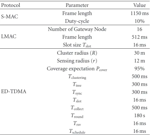
5.2.2. Experiment Setup. Simulation parameters are listed in
Table 4. To S-MAC, a frame is 1150 ms and its duty-cycle is preset to 10%. LMAC is set to operate with the maximum of 32 slots per frame to ensure that all nodes within a two-hop neighborhood can own a slot. Noticeably, the parameters listed in the table are defined in the scenario of 100×100 m2
and packet length is 60 bytes. In the following simulations,
some parameters will change with different settings.
5.2.3. Simulation Results
Scenario 1 (S: 100×100m2,Ldata =60bytes,N: 50∼400, P = 1,Tinterval = 2s). In this scenario, we investigate the
influence of the number of nodes, N, and the simulation
results are shown inFigure 14toFigure 16.
Figure 14plots the average duty-cycle of the three MAC
protocols under different node density. Obviously, duty-cycle
of S-MAC is a constant value predefined before sensors deployment. To LMAC, nodes are active during their allotted slots in each frame even if they do not have data to send, so the duty-cycle of LMAC keeps constant, too. The duty-cycle of ED-TDMA is higher than the other two when the node density is low. However, when node density is high enough, the duty-cycle of ED-TDMA would be less than S-MAC. The reason is that the active time of nodes of ED-TDMA decreases with the increasing node density because of the intracluster coverage scheme, so that the average duty-cycle of ED-TDMA decreases, too. Similarly, the average energy consumption per node of the three protocols is shown in
Figure 15.
Figure 16shows the energy utility efficiency under diff er-ent node density. To S-MAC and LMAC, high node density introduces more collisions and lower throughput with the same energy consumption, which decreases the energy
utility efficiency. In contrast, the energy utility efficiency
of ED-TDMA increases rapidly because its average energy consumption decreases with the increase of node density.
Scenario 2 (Ldata =60bytes,N =500,P =1,Tinterval =2s,
S : 50×50m2 ∼ 600×600m2). Figures 17and 18 show
the influence of area of the monitoring field. As shown in
Figure 17, the energy consumption of S-MAC and LMAC varies a little under different monitoring area and the energy consumption of ED-TDMA increases. The larger the area is, the more average energy consumption of ED-TDMA.
Table4: Simulation II parameters.
Protocol Parameter Value
S-MAC Frame length 1150 ms
Duty-cycle 10%
LMAC
Number of Gateway Node 16 Frame length 512 ms
Slot sizeTslot 16 ms
ED-TDMA
Cluster radius (R) 30 m Sensing radius (r) 12 m Coverage expectationPcover 95%
Tclustering 500 ms
This is because ED-TDMA is a cluster-based protocol, which there would be larger overheads such as cluster management, time synchronization under large monitoring area. For the
same reason, the energy utility efficiency of ED-TDMA then
decreases drastically with the enlargement of monitoring area while the other two increases as described inFigure 18.
Scenario 3 (S : 100×100m2,Ldata = 60bytes,N = 100).
In this scenario, we study the influence of network traffic.
We control network traffic by adjusting packet transmission
interval,Tintervaland transmission probability,P. At first, we setTinterval to 2 s andP varies within [0, 1]. The results are
shown in Figures19and20.
As seen fromFigure 20, the average energy consumption
of LMAC and ED-TDMA both increases when there are
more source nodes. Figure 20shows that the energy utility
efficiency of all the three protocols decreases with the
increasing transmission probability. But S-MAC and ED-TDMA decrease more quickly than LMAC.
Secondly, we setPto 0.3 and changeTintervalfrom 0.5 s∼
7 s. Figures21and22give the results. SmallerTintervalmeans
more data packets are generated per slot. As can be seen, the average energy consumption of the three protocols increases when there are more data packets and their energy utility
efficiency decrease. But ED-TDMA achieves lower energy
consumption and more energy-efficient than the other two.
Scenario 4 (S: 100×100m2,N=100,P=0.3,Tinterval=2s, Ldata : 20 ∼100bytes). The influence of data packet length is analyzed in this scenario and the results are shown in
Figures 23 and 24. As shown in the figures, packet length
0 The number of nodes,N
S MAC LMAC ED TDMA
Figure14: Average duty-cycle versus the number of nodes.
0
200 400 600 800 1000 1200 1400 1600 The number of nodes,N
S MAC LMAC ED TDMA
Figure 15: Average energy consumption versus the number of nodes.
in LMAC. So the energy utility efficiency of LMAC increases
linearly when packet length increases.
6. Conclusion
In this paper, we presented ED-TDMA, an energy-efficient
TDMA protocol for event-driven application for wireless sensor networks. ED-TDMA improves channel utility by changing the length of TDMA frame according to the number of source nodes and saves energy with bitmap-assisted TDMA schedule. In addition, ED-TDMA employs intracluster coverage to prolong network lifetime and to improve system scalability. Compared with contention-based MAC protocol and distributed TDMA scheduling, ED-TDMA performs better for event-driven application in wireless sensor network with high-density deployment and under low traffic. The number of nodes,N
S MAC LMAC ED TDMA
Figure16: Energy utility efficiency versus the number of nodes.
0
Width of monitoring field S MAC
LMAC ED TDMA
Figure17: Average energy consumption versus monitoring area.
0
Width of monitoring field S MAC
LMAC ED TDMA
0
Figure 19: Average energy consumption versus transmission probability.
Figure20: Energy utility efficiency versus transmission probability.
0
Figure21: Average energy consumption versus transmission interval.
0
Figure22: Energy utility efficiency versus transmission interval.
0
Figure23: Average energy consumption versus packet length.
0
Acknowledgment
This work is partially supported by the National Natural Science Foundation of China under Grant no. 60903158, 60703114, 60903156, and 60873026 and the National Grand Fundamental Research 973 Program of China under Grant no.2006CB303000.
References
[1] D. Estrin, R. Govindan, J. Heidemann, and S. Kumar, “Next century challenges: scalable coordination in sensor networks,” in Proceedings of the International Conference on Mobile Computing and Networking (MobiCOM ’99), August 1999. [2] K. Langendoen, Medium Access Control in Wireless Sensor
Networks, Nova Science, 2008.
[3] LAN-MAN Standards Committee of the IEEE Computer Society, Wireless LAN Medium Access Control (MAC) and Physical Layer(PHY) Specification, IEEE, New York, NY, USA, 1997.
[4] W. Ye, J. Heidemann, and D. Estrin, “An energy-efficient MAC protocol for wireless sensor networks,” inProceedings of the IEEE INFOCOM, vol. 3, pp. 1567–1576, New York, NY, USA, June 2002.
[5] T. Van Dam and K. Langendoen, “An adaptive energy-efficient MAC protocol for wireless sensor networks,” inProceedings of the 1st International Conference on Embedded Networked Sensor Systems (SenSys ’03), pp. 171–180, Los Angeles, Calif, USA, November 2003.
[6] S. C. Ergen and P. Varaiya, “PEDAMACS: power efficient and delay aware medium access protocol for sensor networks,” IEEE Transactions on Mobile Computing, vol. 5, no. 7, pp. 920– 930, 2006.
[7] K. Arisha et al., “Energy-aware TDMA-based MAC for sensor networks,” inProceedings of the IEEE Workshop on Integrated Management of Power Aware Communications, Computing and NeTworking (IMPACCT ’02), New York, NY, USA, May 2002. [8] S. Kulkarni et al., “TDMA service for sensor networks,” in
Proceedings of the 24th International Conference on Distributed Computing Systems (ICDCS ’04), pp. 604–609, Tokyo, Japan, March 2004.
[9] G. Pei and C. Chien, “Low power TDMA in large wireless sen-sor networks,” inProceedings of the Military Communications Conference (MILCOM ’01), vol. 1, pp. 347–351, Vienna, Va, USA, October 2001.
[10] J. Li and G. Y. Lazarou, “A bit-map-assisted energy-efficient MAC scheme for wireless sensor networks,” inProceedings of the 3rd International Symposium on Information Processing in Sensor Networks (IPSN ’04), pp. 55–60, New York, NY, USA, April 2004.
[11] L. van Hoesel and P. Havinga, “A lightweight medium access protocol (LMAC) for wireless sensor networks,” inProceedings of the 1st International Workshop on Networked Sensing Systems (INSS ’04), Tokyo, Japan, June 2004.
[12] H. Gong et al., “Traffic adaptive MAC protocol for wireless sensor networks,” inProceedings of the International Confer-ence on Computer Networks and Mobile Computing (ICCNMC ’05), Zhangjiajie, China, August 2005.
[13] V. Rajendran, K. Obraczka, and J. J. Garcia-Luna-Aceves, “Energy-efficient, collision-free medium access control for
wireless sensor networks,” in Proceedings of the 1st Inter-national Conference on Embedded Networked Sensor Systems (SenSys ’03), pp. 181–192, Los Angeles, Calif, USA, November 2003.
[14] I. Rhee, A. Warrier, M. Aia, and J. Min, “Z-MAC: a hybrid MAC for wireless sensor networks,” in Proceedings of the 1st International Conference on Embedded Networked Sensor Systems (SenSys ’03), November 2003.
[15] O. Younis and S. Fahmy, “HEED: a hybrid, energy-efficient, distributed clustering approach for ad hoc sensor networks,” IEEE Transactions on Mobile Computing, vol. 3, no. 4, pp. 366– 379, 2004.
[16] W. B. Heinzelman, A. P. Chandrakasan, and H. Balakrishnan, “An application-specific protocol architecture for wireless microsensor networks,”IEEE Transactions on Wireless Com-munications, vol. 1, no. 4, pp. 660–670, 2002.
[17] H. Zhang and J. C. Hou, “Maintaining scheme coverage and connectivity in large sensor networks,” inProceedings of the NSF International Workshop on Theoretical and Algorithmic Aspects of Sensor, Ad Hoc wireless, and Peer-to-Peer Networks, 2004.
[18] X. Wang, G. Xing, Y. Zhang, C. Lu, R. Pless, and C. Gill, “Integrated coverage and connectivity configuration in wire-less sensor networks,” inProceedings of the 1st International Conference on Embedded Networked Sensor Systems (SenSys ’03), pp. 28–39, ACM Press, November 2003.
[19] Y. Gao, K. Wu, and F. Li, “Analysis on the Redundancy of Wireless Sensor Networks,” in Proceedings of the 2nd ACM International Workshop on Wireless Sensor Networks and Applications (WSNA ’03), pp. 108–114, San Diego, Calif, USA, September 2003.
[20] M. Liu, H. G. Gong, Y. C. Mao, LI. J. Chen, and LI. Xie, “Distributed energy-efficient data gathering and aggregation protocol for wireless sensor networks,”Journal of Software, vol. 16, no. 12, pp. 2106–2116, 2005.