Reconfigurable Hardware Implementations of
Tweakable Enciphering Schemes
Cuauhtemoc Mancillas-L´opez, Debrup Chakraborty and Francisco Rodr´ıguez-Henr´ıquez
Abstract
Tweakable enciphering schemes are length preserving block cipher modes of operation that provide
a strong pseudo-random permutation. It has been suggested that these schemes can be used as the main
building blocks for achieving in-place disk encryption. In the past few years there has been an intense
research activity towards constructing secure and efficient tweakable enciphering schemes. But, actual
experimental performance data of these newly proposed schemes are yet to be reported. Accordingly, in
this paper we present optimized FPGA implementations of five tweakable enciphering schemes, namely,
HCH, HCTR, XCB, EME and TET, using a 128-bit AES core as the underlying block cipher. We report
performance timings of these modes when using both, pipelined and sequential AES structures. The
universal polynomial hash function included in the specification of HCH, HCHfp (a variant of HCH), HCTR, XCB and TET, was implemented using a Karatsuba-Ofman multiplier as the main building block.
We provide detailed analyses of each of the schemes and their experimental performances achieved in
various scenarios. Our experiments show that a sequential AES core is not an attractive option for the
design of these modes as it leads to rather poor throughputs. In contrast, by using an encryption/decryption
pipelined AES core we get a throughput of 3.67 Gbps for HCTR and by using a encryption only pipeline
AES core we get a throughput of 5.71 Gbps for EME. The performance results reported in this paper
provide experimental evidence that hardware implementations of tweakable enciphering schemes can
actually match and even outperform the data rates achieved by state-of-the-technology disk controllers,
thus showing that they might be used for achieving provably secure in-place hard disk encryption.1
The authors are with the Computer Science Department, Centro de Investigaci´on y Estudios Avanzados del IPN, Av. Instituto Polit´ecnico Nacional No. 2508, M´exico D.F 07360
I. INTRODUCTION
A block-cipher mode of operation is a specific way to use a block-cipher to enable it to encrypt arbitrary long messages. In the literature, different kinds of modes of operations have been reported, each providing several security services like confidentiality, authentication, etc. A Tweakable Enciphering Scheme (TES) is a specific kind of mode of operation that is based on the notion of tweakable block ciphers introduced in [18]. TES is a length preserving encryption scheme which can encrypt variable length messages. The security that a TES provides is that of a strong pseudorandom permutation (SPRP), i.e., a TES is considered secure if it is infeasible for any computationally bounded adversary to distinguish between the TES and a random permutation. A TES takes as input a quantity called a tweak other than the message and the key. The tweak is supposed to be a public quantity which enriches the variability of the cipher-text produced.
A fully defined TES for arbitrary length messages using a block cipher was first presented in [12]. In [12] it was also stated that a possible application area for such encryption schemes could be low level disk encryption, where the encryption/decryption algorithm resides on the disk controller which has access to the disk sectors but has no knowledge of the disk’s high level partitions such as directories files, etc. The disk controller encrypts a message before writing it to a specific sector and decrypts the message after reading it from the sector. Additionally it was suggested in [12] that sector addresses can be used as tweaks. Because of the specific nature of this application, a length preserving enciphering scheme is required and under this scenario, a strong pseudorandom permutation can provide the highest possible security.
In the last few years there have been numerous proposals for TES. These proposals fall in three basic categories: Encrypt-Mask-Encrypt type, Hash-ECB-Hash type and Hash-Counter-Hash type. CMC [12], EME [13], EME∗ [10] fall under the Encrypt-Mask-Encrypt group. PEP [4], TET [11], HEH [31] fall
under the ECB-Hash type and XCB [24], HCTR [34], HCH [5], ABL [26] fall under the Hash-Counter-Hash type.
argument, however, can only be sustained if one assumes a software implementation of the mode, where a block-cipher call has the same cost regardless of the data dependencies. It is noticed that this is not the case for a hardware design, where block-cipher invocations can have different timing costs according to the way that the cipher core is implemented (using either a sequential or a pipeline architecture) and the data dependencies associated with the particular mode of operation algorithm under analysis. The same arguments hold for the multipliers as one can have a fully parallel efficient multiplier which can multiply two field elements in one clock-cycle.
A speculative performance comparison of the EME∗, XCB, HCH and TET modes of operation in
hardware is provided in [11]. This comparison assumes the same hardware implementation setting reported in [2], where a fully-parallel GF(2n) field multiplier was implemented in one clock cycle at a hardware cost in area of about three times the cost associated with one AES round function, and where the AES core is implemented through the computation of ten such modules. However, this analysis might not be quite accurate because, as we will see in the rest of this paper, one can implement a GF(2n) field multiplier with an efficiency comparable to the one of an AES round function in terms of both, the critical path and the cost in area.
Keeping in mind the specific application goal of low level disk encryption, a comparative study of performance and cost of the various proposed schemes in hardware is very necessary. The recent standardization activities for such modes by the IEEE working group on storage security [15] also demands performance data for the many proposed schemes.
In this paper we present optimized hardware implementation of five TES. The modes we chose are HCH, HCTR, XCB, EME and TET. Also we provide performance data for a variant of HCH, called HCHfp, which is particularly useful for disk encryption. The rationale behind the choice of these specific modes is discussed next.
The modes that we left out in this study are CMC, PEP, EME∗, ABL and HEH. CMC which uses two
layers of CBC type encryption cannot be pipelined. PEP and ABL are particularly inefficient compared to their counterparts. EME∗is a modification over EME so that it can be used for arbitrary length messages.
For the application of disk sector encryption this functionality is not required. HEH is a recently proposed mode which improves the TET mode of operation. HEH is supposed to be more efficient than TET in certain scenarios. In this work we do not provide performance data for HEH, but we provide some discussions and speculations regarding its performance.
and present our design decisions and finally report hardware performance data of the five modes. Our implementations show that in terms of area HCTR, HCH, TET and XCB require more area than EME. HCTR performs the best in terms of speed followed by HCHfp, EME, TET, HCH and XCB.
II. NOTATIONS
An n-bit block cipher is a functionE:K × {0,1}n→ {0,1}n, whereK 6=∅is the key space and for anyK∈ K,E(K, .) is a permutation. We writeEK( )instead ofE(K, .). We shall generally denote the block-length by n and the number of blocks by m. By X||Y we shall mean the concatenation of two binary strings X andY andbinn(|X|) will denote then-bit binary representation of|X|, which denotes the length ofX. By padr(X) we shall mean concatenation r zeros to the end of X and dropr(X) will denote ther ≤ |X| most significant bits of X.
We will treat n bit strings as polynomials of degree less thann with coefficients inGF(2), thus they are elements of the field GF(2n). IfX andY arenbit strings then byX⊕Y we shall mean a addition in the field and by XY a multiplication in the field. The operation X⊕Y can be easily performed by a bitwise xor of X and Y and XY can be realized as a multiplication of the polynomials X and Y modulo a fixed polynomial P(x) of degree n irreducible over GF(2). By xX we would represent the field multiplication ofX by the polynomial x.
III. THESCHEMES
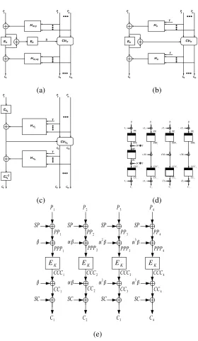
In the subsequent subsections we discuss the constructions of the modes HCH, HCTR, XCB, EME and TET. A pictorial high level description of the five modes are provided in Fig. 1.
A. HCH
As mentioned earlier HCH falls under the category of Hash-Counter-Hash constructions. HCH uses an universal hash function of the form:
HR,Q(A1, . . . , Am) = Q⊕A1⊕A2Rm−1⊕A3Rm−2· · · ⊕Am−1R2⊕AmR (1)
Where A1, A2, . . . , Am, R, Q are nbit strings. In addition to the hash function HCH requires a counter mode of operation. Given an n-bit string S, a sequence S1, . . . , Sm is defined, where each Si depends on S. Given such a sequence and a key K the counter mode is defined as follows.
1
P P2 Pm
C1 C2 Cm
CtrK
HR,Q
HR,xQ
EK EK
S
1
P P2 Pm
C1 C2 Cm
Hh
Hh
EK CtrK
T
T
(a) (b)
K1
H
HK3
EK0 1
P P
2 Pm
C2
C1 Cm
EK4
−1
C2 Cm
K2
T
T Ctr
P1 P2 P3 P4
L
x x2L x3L
M
x x2M x3M
L
x x2L x3L C1 C2 C3 C4
PPP1 PPP2 PPP3 PPP4
PP4
PP3
PP2
PP1
CCC1 CCC2 CCC3 CCC4
CC1 CC2 CC3 CC4
L SP T L T SC MP MC (c) (d) (e)
Fig. 1. High level block diagram of the schemes: (a) Encryption using HCH. HereR=EK(T)andQ=EK(R⊕binn(l)),
wherelis the total length of the plain-text. (b) Encryption using HCTR. HereKis the key for the block cipherEK()andhis
the key for the universal hash functionHh(). (c) Encryption using XCB, here 3 block cipher keys and 2 hash keys are derived
using a single keyK. (d) Encryption of 4 blocks of plaintext using EME. Here,L=xEK(0n),SP =P P P2⊕P P P3⊕P P P4,
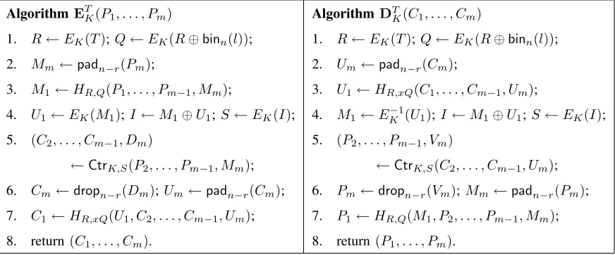
Fig. 2. Encryption and decryption using HCH. The tweak isT and the key isK. For1≤i≤m−1,|Pi|=nand|Pm|=r
wherer≤n.
Algorithm ET
K(P1, . . . , Pm)
1. R←EK(T);Q←EK(R⊕binn(l));
2. Mm←padn−r(Pm);
3. M1←HR,Q(P1, . . . , Pm−1, Mm);
4. U1←EK(M1);I←M1⊕U1;S←EK(I);
5. (C2, . . . , Cm−1, Dm)
←CtrK,S(P2, . . . , Pm−1, Mm);
6. Cm←dropn−r(Dm); Um←padn−r(Cm);
7. C1←HR,xQ(U1, C2, . . . , Cm−1, Um);
8. return(C1, . . . , Cm).
Algorithm DT
K(C1, . . . , Cm)
1. R←EK(T); Q←EK(R⊕binn(l));
2. Um←padn−r(Cm);
3. U1←HR,xQ(C1, . . . , Cm−1, Um);
4. M1←EK−1(U1); I←M1⊕U1;S ←EK(I);
5. (P2, . . . , Pm−1, Vm)
←CtrK,S(C2, . . . , Cm−1, Um);
6. Pm←dropn−r(Vm);Mm←padn−r(Pm);
7. P1←HR,Q(M1, P2, . . . , Pm−1, Mm);
8. return(P1, . . . , Pm).
Among various choices of the sequence Si, in [5] the authors propose the use ofSi =S⊕binn(i). In our implementations we also stick to this definition of the counter mode.
The complete encryption and decryption algorithm of HCH is given in Fig. 2. A schematic diagram of encryption is given in Fig. 1(a).
HCH can encrypt arbitrary long messages greater thannbits. It uses a single key which is same as the block-cipher key. It requiresm+ 3block cipher calls and2m−2finite field multiplications to encrypt a m block message. The key for the universal hash is R, which is derived by encrypting the tweak. Thus R changes across encryption calls and this does not allow the use of pre-computations for computing the hash. HCH requires two passes over the data.
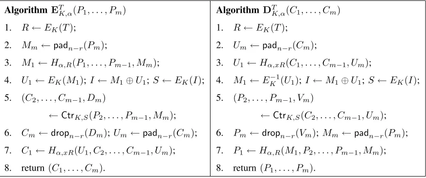
In [6] a modification of HCH is also proposed which is called HCHfp. HCHfp uses a different hash key which is not dependent on the tweak but is randomly chosen by the user. In HCHfp pre-computation can be possible. Another modification of HCH reported in [6] is HCHfp. HCHfp can only be used in those applications where the message length is fixed. This construction simplifies the general HCH mode and requires one less cipher call, but it requires two separate keys for the hash and the block-cipher. Thus, pre-computation for computing the hash is also possible in HCHfp. HCHfp is particularly of interest for disk encryption applications as here the message length is fixed and same as the sector length. The encryption-decryption algorithm using HCHfp is provided in Fig. 3.
compu-Fig. 3. Encryption and decryption using HCHfp. The tweak isT and the key is(K, α), whereKis the block cipher key and
αis the universal hash key. The number of blocksmis fixed.
Algorithm ET
K,α(P1, . . . , Pm)
1. R←EK(T);
2. Mm←padn−r(Pm);
3. M1←Hα,R(P1, . . . , Pm−1, Mm);
4. U1←EK(M1);I←M1⊕U1;S←EK(I);
5. (C2, . . . , Cm−1, Dm)
←CtrK,S(P2, . . . , Pm−1, Mm);
6. Cm←dropn−r(Dm); Um←padn−r(Cm);
7. C1←Hα,xR(U1, C2, . . . , Cm−1, Um);
8. return(C1, . . . , Cm).
Algorithm DT
K,α(C1, . . . , Cm)
1. R←EK(T);
2. Um←padn−r(Cm);
3. U1←Hα,xR(C1, . . . , Cm−1, Um);
4. M1←EK−1(U1); I←M1⊕U1;S ←EK(I);
5. (P2, . . . , Pm−1, Vm)
←CtrK,S(C2, . . . , Cm−1, Um);
6. Pm←dropn−r(Vm);Mm←padn−r(Pm);
7. P1←Hα,R(M1, P2, . . . , Pm−1, Mm);
8. return(P1, . . . , Pm).
tationally bounded chosen plaintext chosen ciphertext adversary in distinguishing HCH from a random permutation can be at most O(σ2
n)/2n +δ where σn denotes the number of n bit plaintexts and/or ciphertexts the adversary has access to, and δ denotes the advantage of an adversary to distinguish the underlying block-cipher from a random permutation.
B. HCTR
The structure of HCTR is similar to that of HCH with some important differences. The hash used in case of HCTR is defined as:
Hh(X) =X1hm+1⊕X2hm⊕. . .⊕padn−|Xm|(Xm)h 2⊕bin
n(|X|)h (3) Where h is the hash key and X = X1||X2||. . .||Xm||, where |Xi|= n bits (i = 1,2, . . . m−1) and |Xm| ≤n.
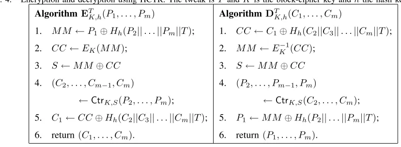
The counter mode used in HCTR is the same as in (2). The encryption and decryption operations using HCTR are described in Fig. 4, and a high-level description is provided in Fig. 1(b).
HCTR can also encrypt arbitrary long messages. It requires m block cipher calls and 2m+ 2 field multiplications to encrypt anmblock message. It requires two different keys and it is proved to be secure with a security bound of O(σ3
Fig. 4. Encryption and decryption using HCTR. The tweak isT andKis the block-cipher key andhthe hash key.
AlgorithmET
K,h(P1, . . . , Pm)
1. M M←P1⊕Hh(P2||. . .||Pm||T);
2. CC←EK(M M);
3. S←M M⊕CC
4. (C2, . . . , Cm−1, Cm)
←CtrK,S(P2, . . . , Pm);
5. C1←CC⊕Hh(C2||C3||. . .||Cm||T);
6. return(C1, . . . , Cm).
Algorithm DT
K,h(C1, . . . , Cm)
1. CC←C1⊕Hh(C2||C3||. . .||Cm||T);
2. M M←EK−1(CC);
3. S←M M⊕CC
4. (P2, . . . , Pm−1, Pm)
←CtrK,S(C2, . . . , Cm);
5. P1←M M⊕Hh(P2||. . .||Pm||T);
6. return(P1, . . . , Pm).
C. XCB
XCB is another mode which belongs to the hash-counter-hash family of constructions. XCB uses a hash hhh(h, X, T) which takes as inputs an n-bit hash key h along with two strings X and T. Let X = X1||. . .||Xm and T = T1||. . .||Tm0 where |Xi| = n for i = 1,2, . . . m, and |Ti| = n for
i= 1,2, . . . m0. The last block for both X and T can be incomplete.hhh
h(X, T) is defined as
hhhh(X, T) = (X1hm+m
0+1
+X2hm+m
0
+. . .pad(Xm)hm
0+2
) +
(T1hm
0+1
+T2hm
0
+. . .pad(Tm0 )h2) + (`(X)||`(T))h. (4)
Where `(X) and `(T) represent the n/2 bit binary representation of |X| and |T|, respectively. The counter mode of XCB is defined as in (2), but they defineSi =incri(S), whereincr(S) increments the last32 bits ofS modulo 232. The encryption and decryption using XCB is shown in Fig. 5. A highlevel description is provided in Fig. 1(c).
The variant of XCB that we present in Fig. 5, has no security proof. The authors suggested some minor modifications of the original proposal in [25] and provided a security proof for it. In terms of efficiency it seems that the two variants are not much different.
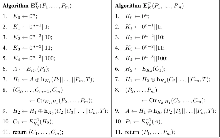
Fig. 5. Encryption and decryption using XCB. The tweak isT and Kis the key from which two different hash keys and 3 different block-cipher keys are derived.
AlgorithmET
K(P1, . . . , Pm)
1. K0←0n;
2. K1←0n−1||1;
3. K2←0n−2||10;
4. K3←0n−2||11;
5. K4←0n−3||100;
6. A←EK0(P1);
7. H1←A⊕hK1(P2||. . .||Pm, T);
8. (C2, . . . , Cm−1, Cm)
←CtrK2,H1(P2, . . . , Pm);
9. H2←H1⊕hK3(C2||C3||. . .||Cm, T);
10. C1←E−1
K4(H2);
11. return(C1, . . . , Cm);
Algorithm ET
K(P1, . . . , Pm)
1. K0←0n;
2. K1←0n−1||1;
3. K2←0n−2||10;
4. K3←0n−2||11;
5. K4←0n−3||100;
6. H2←EK4(C1);
7. H1←H2⊕hK3(C2||. . .||Cm, T);
8. (P2, . . . , Pm)
←CtrK2,H1(C2, . . . , Cm);
9. A←H1⊕hK1(P2||P3||. . .||Pm, T);
10. P1←E−1
K0(A);
11. return(P1, . . . , Pm);
D. EME
Now we will discuss a disk encryption mode called ECB-Mask-ECB (EME) [13]. As the name suggests, the mode consists of two electronic code-book layers with a masking layer in between.
The structure of EME is quite different from HCH and HCTR. EME falls under the category of Encrypt-mask-Encrypt constructions. It does not use any hash function, but instead uses two layers of encryption. The encryption and decryption algorithms are given in Fig. 6. A pictorial description of EME is given in Fig. 1(d).
EME requires 2m+ 2block cipher calls for encrypting an m block message. It requires no multipli-cation. EME uses a single key same as the block-cipher key. EME has some message length restrictions. If the block length of the underlying block cipher is n then the message length should always be a multiple of n. Moreover, EME cannot encrypt more than n blocks of messages. This means that if an AES-128 is used as the underlying block-cipher then EME cannot encrypt more than 2048 bytes (2 KB) of data. This message length restriction was removed in a construction called EME∗which requires more
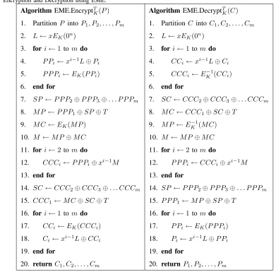
Fig. 6. Encryption and Decryption using EME.
Algorithm EME.EncryptT K(P)
1. Partition P intoP1, P2, . . . , Pm
2. L←xEK(0n)
3. fori←1tom do 4. P Pi ←xi−1L⊕Pi
5. P P Pi←EK(P Pi)
6. end for
7. SP ←P P P2⊕P P P3⊕. . . P P Pm
8. M P ←P P P1⊕SP⊕T
9. M C←EK(M P)
10. M ←M P⊕M C
11. fori←2tom do
12. CCCi←P P Pi⊕xi−1M
13. end for
14. SC←CCC2⊕CCC3⊕. . . CCCm
15. CCC1←M C⊕SC⊕T
16. fori←1tom do
17. CCi←EK(CCCi)
18. Ci←xi−1L⊕CCi
19. end for
20. returnC1, C2, . . . , Cm
Algorithm EME.DecryptT K(C)
1. Partition C intoC1, C2, . . . , Cm
2. L←xEK(0n)
3. fori←1 tomdo 4. CCi ←xi−1L⊕Ci
5. CCCi←EK−1(CCi)
6. end for
7. SC←CCC2⊕CCC3⊕. . . CCCm
8. M C←CCC1⊕SC⊕T
9. M P ←EK−1(M C)
10. M ←M P ⊕M C
11. fori←2 tomdo
12. P P Pi←CCCi⊕xi−1M
13. end for
14. SP ←P P P2⊕P P P3⊕. . . P P Pm
15. P P P1←M P⊕SP⊕T
16. fori←1 tomdo
17. P Pi←EK(P P Pi)
18. Pi←xi−1L⊕P Pi
19. end for
20. returnP1, P2, . . . , Pm
ofO(σ2)/2n+δ.
E. TET
TET uses two layers of block-wise invertible universal hash functions with an ECB layer of encryption in-between them. To compute the hash function, TET requires a hash key τ which requires certain properties. To ensure invertibility of the hash function, τ must be such that for a m block message σ=Pmi=1τm6= 0. For this to be true one requires different hash keys for different message lengths. The authors propose a way to generate the hash key τ for different messages using a key. The encryption algorithm also requires the value of σ−1. This makes TET rather complicated for applications which
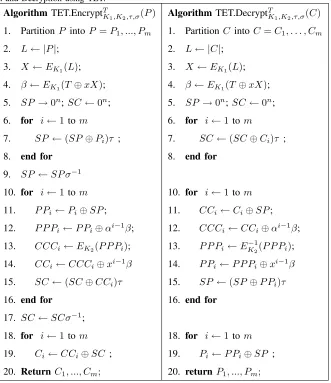
Fig. 7. Encryption and Decryption using TET.
Algorithm TET.EncryptT
K1,K2,τ,σ(P)
1. Partition P intoP =P1, ..., Pm
2. L← |P|;
3. X←EK1(L);
4. β←EK1(T⊕xX);
5. SP→0n; SC←0n;
6. for i←1tom
7. SP←(SP⊕Pi)τ ;
8. end for
9. SP←SP σ−1
10. for i←1tom
11. P Pi←Pi⊕SP;
12. P P Pi ←P Pi⊕αi−1β;
13. CCCi←EK2(P P Pi);
14. CCi←CCCi⊕xi−1β
15. SC←(SC⊕CCi)τ
16. end for
17. SC←SCσ−1;
18. for i←1tom
19. Ci←CCi⊕SC ;
20. ReturnC1, ..., Cm;
Algorithm TET.DecryptT
K1,K2,τ,σ(C)
1. Partition C intoC=C1, . . . , Cm
2. L← |C|;
3. X ←EK1(L);
4. β ←EK1(T⊕xX);
5. SP →0n;SC←0n;
6. for i←1 tom
7. SC←(SC⊕Ci)τ ;
8. end for
10. for i←1 tom
11. CCi←Ci⊕SP;
12. CCCi ←CCi⊕αi−1β;
13. P P Pi←EK−21(P P Pi);
14. P Pi ←P P Pi⊕xi−1β
15. SP ←(SP⊕P Pi)τ
16. end for
18. for i←1 tom
19. Pi←P Pi⊕SP ;
20. return P1, ..., Pm;
messages, we present the TET algorithm only for fixed lengths which are multiples of the block length of the block-cipher. Also we assume a fixed value ofτ and pre-computed values ofσ−1. The algorithm
for TET is shown in Figure 7. A high level description is provided in Fig 1(e). Note, that the encryption and decryption operations in TET are quite different. Compared with TET decryption operation, the encryption operation requires two extra multiplications by σ−1.
TABLE I
SUMMARY OF THE CHARACTERISTICS OF THE FIVETESDESCRIBED. THE FIGURES ARE CONSIDERING A FIXED LENGTHm
BLOCK MESSAGE.
Mode BC Calls Field Mult. no. of keys
HCH m+ 3 2(m−1) 1 HCHfp m+ 2 2(m−1) 2
HCTR m 2(m+ 1) 2
XCB m+6 2(m+ 1) 1
EME 2(m+ 1) 0 1
TET m+ 2 2m + 2 3
IV. DESIGNDECISIONS
For implementing all five schemes we chose the underlying block cipher as AES-128. As it was mentioned in the Introduction, the designs that we present here are directed towards the application of disk sector encryption. In this specific application the messages are all of fixed length and we consider them to be multiples of 128 bits. In particular, our designs are optimized for applications where the sector length is fixed to 512 bytes. As the sector address is considered to be the tweak, thus the tweak length itself is considered to be fixed and equal to one block length of the block cipher.
The speed of a low level disk encryption algorithm must meet the current possible data rates of disk controllers. With emerging technologies like serial ATA and Native Command Queuing (NCQ) the modern day disks can provide data rates around 3Giga-bits per second[32]. Thus, the design objective should be to achieve an encryption/decryption speed which matches this data rate.
The modes HCH, HCTR, XCB and TET use two basic building blocks, namely, a polynomial universal hash and the block-cipher. EME requires only a block-cipher. Since AES-128 was our selection for the underlying block-cipher, proper design decisions for the AES structure must meet the desired speed. Out of many possible designs reported in the literature [19], [9], [3], [14], [8] we decided to design the AES core so that a 10-stage pipeline architecture could be used to implement the different functionalities of the counter mode, the electronic code book (ECB) mode and the encryption of one single block that we will call in the rest of this paper single mode.
stages have been reported [16], but such designs would increase the latency, i.e., the total delay before a single block of cipher-text can be produced. As the message lengths in the target application are specifically small (in particular the most used sector size is of 512 bytes), such pipeline designs are not suitable for our target application.
The main building block needed in the polynomial hash included in the specification of the HCH, HCTR, XCB and TET modes, is an efficient multiplier in the field GF(2128). Out of many possible
choices we selected a fully parallel Karatsuba-Ofman multiplier which can multiply two 128-bit strings in a single clock-cycle at a sub-quadratic computational cost [30]. This time efficient multiplier occupies about 1.4 times the hardware resources required by one single AES round.2. Because of this, the total hardware area of EME (which does not require multipliers) is significantly lesser than that required by the other modes that we study. A more compact multiplier selection would yield significantly lower speeds which violates the design objective of optimizing for speed.
It is noted that the specifications of HCTR, XCB, TET and HCHfp algorithms imply that one multipli-cand is always fixed, thus allowing the usage of pre-computed look up tables that can significantly speed up the multiplication operation. Techniques to speed up multiplication by look-up tables are discussed in [33], [23], [27], [2] for the software platform scenario. These techniques can be somehow be extended to hardware implementations also. However, there is a tradeoff in the amount of speed that can be obtained by means of pre-computation and the amount of data that needs to be stored in tables. Significantly higher speeds can be obtained if one stores large tables. This speedup thus comes with an additional cost of area and also the potentially devastating penalty of secure storage. Moreover, if pre-computation is used in a hardware design then the key needs to be hardwired in the circuit which can lead to numerous difficulties in key setup phases and result in lack of flexibility for changing keys. Because of the above considerations, we chose not to store key related tables for our implementations. Thus the use of an efficient but large multiplier is justified in the scenario under analysis.3 Regarding storage of key related materials we make an exception to this in case of TET. TET requires computation of a inverse, which is a particularly expensive arithmetic operation. In case of TET we store the hash key τ along with the pre-computed value of σ−1, this storage helps us to get rid of a field inversion circuit but does not help
us to speed up multiplications.
We implemented the schemes on a FPGA device which operates at lower frequencies than true VLSI
2For specific experimental details see Table II.
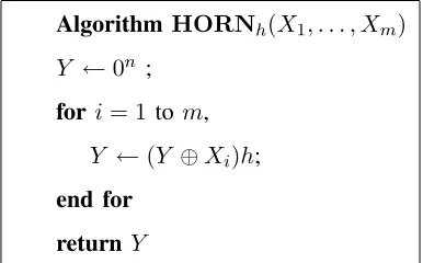
Fig. 8. The Horner’s Rule
Algorithm HORNh(X1, . . . , Xm)
Y ←0n ;
for i= 1 to m,
Y ←(Y ⊕Xi)h;
end for
return Y
circuits. Thus the throughput that we obtain probably can be much improved if we use the same design strategies on a CMOS VLSI technology. Our target device was a XILINX Virtex 4, xc4v1x100-12FF1148.
V. THEDESIGNOVERVIEWS
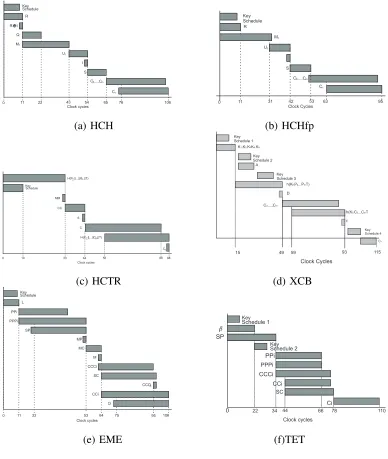
In this Section we give a careful analysis of the modes’ data dependencies and we explain how the parallelism present in the algorithms can be exploited. In the analysis which follows we assume the message to be of 512 bytes (32 AES blocks). Furthermore, we assume a single AES core designed with a 10 stage pipeline and a fully parallel single clock cycle multiplier. We also calculate the key schedules for AES on the fly, this computation can be parallelized with the AES rounds. The polynomial universal hash functions are computed using the Horner’s rule shown in the algorithm of Fig. 8:
A. HCH mode of Operation
Referring to the Algorithm of Fig. 2 the algorithm starts with the computation of the parameter R in Step 1. For computingR the AES pipeline cannot be utilized and must be accomplished in simple mode, implying that 11 clock cycles will be required for computingR. At the same time, the AES round keys can be computed by executing concurrently the AES key schedule algorithm. The hash function of Step 3 can be written as
HR,Q(P1, P2, . . . P32) =P1⊕Q⊕Z
where Z = HORNR(P2, . . . P32). So, Z and Q can be computed in parallel. For computing Z, 31
The counter mode in step 5 requires 31 blockcipher calls which can be pipelined. So computation of step 5 requires a total of 30 + 11 = 41 clock cycles. The first cipher block C2 is produced 11 clock
cycles after the counter starts. The second hash function computation of Step 7 can start as soon asC2
is available in the clock cycle 75. Hence the computation of the hash function can be completed at the same time that the last cipher block (Cm) of Step 5 is produced. Figure 9(a) depicts above analysis. It can be seen that a valid output will be ready after the cycle 75 and a whole disk sector will be ready in the cycle 106. In case of HCHfp the computation ofQ is not required, and it uses a hash key which is different fromR. ThusRand the hash function can be computed in parallel, which gives rise to a savings of 11 clock cycles. So HCHfp will produce a valid output in 64 clocks and it will take 95 clock-cycles to encrypt the 32 block message (see Figure 9(b)).
B. HCTR Mode of Operation
Referring to the Algorithm of Fig. 4, the computation of the hash function of Step 1 requires 33 clock cycles. At the same time, the design can derive the AES round keys by executing concurrently the AES key schedule algorithm. Then, the computation of the parameter CC in Step 2, must be accomplished in simple AES mode, implying that 11 clock cycles will be required for completing that calculation. As in HCH mode, the m−1 block cipher calls included in Step 4 are performed in counter mode, which once again can be computed in parallel via the pipeline architecture. Hence, the computation of all the Ci for i= 2, . . . , m= 32, can be computed in(32−1) + 11 = 42 clock cycles. At the same time, the second hash function computation of Step 7 can start as soon as C2 is available in the clock cycle 56.
Hence the computation of the hash function can be completed at the same time that the last block cipher (Cm) of Step 5 is produced. Figure 9(c) depicts the timing analysis just given. It can be seen that a valid output will be ready after the cycle 55 and a whole disk sector will be ready in the cycle 88.
C. XCB Mode of operation
the key schedule and the decryption requires another 21 clock cycles, and a reset operation is necessary before computing the new key schedule. This thus gives rise to a requirement of 115 clock cycles to encrypt the whole sector. But the first cipher block would be ready in case of XCB after clock cycle 59.
D. EME mode of Operation
Referring to the Algorithm of Fig. 6, the computation of the parameter L in Step 2, must be ac-complished in a sequential fashion, implying that 11 clock cycles will be required for completing that calculation. Thereafter, the 32 block cipher calls included in Steps 3-6 can be accomplished using the benefits of the parallelism associated to the pipeline approach. So, the computation of all the P P Pi for i= 1,2, . . . , m= 32, can be computed in (32−1) + 11 = 42 clock cycles. On the contrary, the cipher call in Step 9 for obtainingM C must be performed in a sequential fashion, which implies 11 extra clock cycles. The second layer of encryption can also be performed in 42 clock cycles and the operationsxiM andxiL in steps 12 and 18 can be parallelized with the block-cipher calls. So to complete encryption of 32 blocks EME should require11 + 42 + 11 + 42 = 106clock cycles. And the first block of valid output would be produced after 75 clock cycles. Some pre-computations may save some of the EME costs. For example,L in Step 2 is a quantity only dependent on the key K, thus, L can be pre-computed yielding the saving of 11 clock cycles. But this will require storage of key materials. Figure 9 (e) shows the EME operations that are suitable for being computed in parallel.
E. TET mode of Operation
Referring to the algorithm of Fig. 7, the computation of the parameter β requires two AES calls in the simple mode, which can be accomplished in 22 clock cycles. The computation of SP can be done in parallel. Computation of SP will require 32 multiplications which can be completed in 33 clock cycles. In encryption it requires an extra multiplication withσ−1, Thus the computation of SP would be
complete in 34 clock cycles. In the mean-time the key schedule for the second block-cipher key can also be completed. The computation of P Pi and P P Pi can be parallelized and they can be computed in 33 clock cycles. As soon as P P P1 is available (which would be available at clock cycle 35), computation
Key Schedule R l R Q M1 I U S 1
C,...,C2 m
1
C
0 11 22 43 54 65 76 106
Clock cycles R M1 U S 1
C,...,C2 m
1
C
0 11
Clock Cycles
31 42 53 63 95
Key Schedule
(a) HCH (b) HCHfp
Key Schedule MM CC S C C
0 10 33 44 55 88
Clock cycles H(P ||...||P ||T)2 m
H(C ||...||C ||T)2 m
86 1 Key Schedule 1 Key Schedule 2 Key Schedule 4
h(K C ...C T5,2 m
D
C ,...,C2 m
F
C1 h(K P ...P T)5,2 m
15
K K K1,2,3K K4,5
49 59 93 115
A
Clock Cycles Key
Schedule 3
(c) HCTR (d) XCB
L PPi PPPi SP MP MC M CCCi SC CCC CCi Ci 1
0 11 22 53 64 75 95 106
Clock cycles Key Schedule PPi PPPi SP CCCi SC CCi 0 22 Clock cycles Key Schedule 1 Key Schedule 2
34 66 78 110
Ci
44
(e) EME (f)TET
Fig. 9. Timing diagrams
cycles. Note that in this analysis we do not consider computation of the inverse, which may give rise to a significant increase in the number of the required clock cycles.
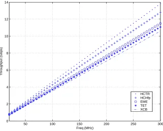
50 100 150 200 250 300 0
2 4 6 8 10 12 14
Freq (MHz)
Throughput (Gbps)
HCTR HCHfp EME TET XCB
Fig. 10. Throughput Vs. Frequency for the Five TES
The above analysis of the algorithms that we presented is independent of any implementation strategy. It seems that the number of clock cycles required for each of the algorithms cannot be further reduced if the design decisions taken by us are followed (10 stage AES pipeline and 1 clock cycle multiplier). Pre-computation in the multiplier or other multiplication strategies can bring down the cost of computing the hash function in HCHfp, HCTR and TET.
VI. IMPLEMENTATIONASPECTS
In practice, the timing performance of a generic hardware design will be determined by its associated critical path. As for the area utilization of a given design, some of the factors that have impact in hardware resource utilization include: the number of temporary variables involved in the design (which implies extra registers) and the number of possible inputs that the main building blocks may have (which translates in extra multiplexer blocks).
TABLE II
PERFORMANCE OF ANENCRYPTION/DECRYPTIONAESROUND AND A128-BITFULLY-PARALLELKARATSUBA-OFMAN
MULTIPLIER
Design Slices B-RAM Critical Path(nS)
Full AES round 1215 8 10.998
Encryption-only AES round 298 8 6.71
multiplier 3223 - 9.85
Karatsuba-Ofman multiplier.4
Considering the utilization of B-RAMs and slices, the size of one full AES round in our design is about 30% smaller than that of the Karatsuba-Ofman multiplier. However, the critical path delay associated to an encryption/decryption AES round, is longer than that of the multiplier block by about 10%.
TABLE III
HARDWARERESOURCESUTILIZED BY THEFIVETES
Modo Mux Extra Mul Registers Mux Mux
inAES B-RAM xtime 128bits 2×128 3×128
HCTR 3×128 - - 3 2 1
HCHfp 4×128 - 1 5 5
-HCH 5×128 - 1 6 5
-EME 4×128 2 3 5 5
-TET 3×128 2 3 2 4
-XCB 4×128 - - 8 6 2
Table III shows the hardware resource usage by each of the five TES modes of operation. Besides an obvious impact in the area complexity of the modes, the resources occupied by each TES tend to increase its critical path. In the rest of this Section, we briefly analyze the resource utilization and timing potential performance of the five TES modes under analysis.
4The experimental results shown in Table II correspond to a place &route simulations using Modelsim XE III 6.0d and Xilinx
A. HCH and HCHfp
For HCH and HCHfp the critical path will be also lower bounded by the minimum critical path between the AES core and the hash function. Considering the values given in Table II the maximum throughputs that we can expect for these two modes when using the full and the encryption-only AES cores is 3.8 Gbps and 4.24 Gbps, respectively. However, we should expect that HCH and HCHfp timing performances will be appreciably lower than those bounds, because these modes requires six and five extra registers for temporary variables, respectively. Moreover as shown in Table III, the possible inputs for the AES core and the hash function is more than that of HCTR, which will force us to use multiplexer blocks with more inputs.
B. HCTR
As shown in Table III, HCTR requires three extra 128-bit registers in order to allocate temporary computation values and also the possible inputs for the AES core and the hash function is three. This feature makes HCTR both, a fast an economical TES mode. The critical path of HCTR will be lower bounded by the one associated to either the hash function or the AES core, whichever is larger. Therefore, and according to the critical paths reported in Table II, we can expect that an implementation of HCTR will have a critical path of at least 10.998ηS when using the full AES core and 9.85ηS when using the encryption-only AES round. In terms of throughput, this translates to a maximum of 4.185 Gbps and 4.672 Gbps, respectively.
C. XCB
Out of the five modes analyzed, XCB is both, the most expensive in terms of hardware resource utilization, and the slowest. XCB’s latency however, is relatively low but the total time required is quite high. Among other factors, XCB’s total time is high because in its final step the calculation of EK−1 cannot start till a key schedule computation of C1 has finished. In total, 21 clock cycles are consumed
in that final step. As shown in Table III, storage of XCB temporary variables requires eight extra 128-bit registers and one 128-bit four-to-one multiplexer. Thus, the maximum throughput that one can expect for XCB when using the full and the encryption-only AES cores should be significantly lower than 3.21 Gbps and 3.59 Gbps, respectively.
D. EME
cAES c/d mcms readyAES inAES S
key
outh cH readyH inH
Control Unit
outAES AES counter
and
Hash simple
R Q
Fig. 11. HCH Main Architecture
along with the chain additions characteristic of this mode.5 Since the xtimeoperation can be performed efficiently in hardware, the critical path of EME is mainly given by that of the AES core utilized. Hence, we can expect that an implementation of EME will have a critical path of at least 10.998ηS when using the full AES core and 6.71 ηS when using the encryption-only AES round. In terms of throughput, this translates to a maximum of 3.48 Gbps and 5.71 Gbps, respectively. Regarding area utilization, EME is consistently the most economical TES mode. However, the computation of EME requires to store all the P P Pi values for i= 2, . . . , m. This issue was solved by utilizing two extra FPGA block RAMs as reported in Table III.
E. TET
Reg Q
Reg R
Reg S
Reg I
Reg U 1 Mul x2
Reg M 1
T
States
Machine
inH resetH outH readyH Q
R
in
c/d mcms cAES readyAES inAES outAES S
len
outHCH HCH
readyHCH
Fig. 12. HCH Control Unit Architecture
VII. ARCHITECTURE OFHCH
As a representative design example we shall discuss the architecture of HCH in details. The architectures for the other modes are quite similar and we do not discuss them here.
A. HCH Implementation
Fig. 11 shows the general architecture of the HCH mode of operation. It can be seen that AES must be implemented both, in counter and in simple mode. Moreover a hash function is also required as one of the main building blocks. Design details of both, the AES core and the hash function can be found in the Appendix.
The architecture operation is synchronized through a control unit that performs the adequate sequence of operations in order to obtain a valid output.
The HCH control unit architecture is shown in Fig. 12. It controls the AES block by means of four 1-bit signals, namely:cAES that initializes the round counter, thec/dsignal that selects between encryption or decryption mode, the msms signal that indicates whether one single block must be processed or rather, multiple blocks by means of the counter mode. Finally, readyAES indicates whenever the architecture has just computed a valid output. The AES dataflow is carried out through the usage of three 128-bit busses, namely,inAESthat receives the blocks to be encrypted,outAESthat sends the encrypted blocks
Fig. 13. HCH State Machine Diagram
andS that receives the initialization parameter for the counter mode. The communication with the hash function block is done using two signals: cH for initializing the accumulator register and the counter of blocks already processed andreadyHthat indicates that the hash function computation is ready. The data input/output is carried by theinHandoutHbusses, respectively. The parametersRandQare calculated in the control unit and send through the busses to the hash function.
The HCH control unit implements a finite state automaton that executes the HCH sequence of op-erations. It defines the following eight states:RESET, AES1, AES2, HASH1, AES3, AES4, ECOUNTER
and HASH2. In each state, an appropriate control word is generated in order to perform the required operations. The correct algorithm execution requires storing theR, Q, S,I,U1 andM1 values. Thus, six
extra 128-bit registers are needed. In particular the hash function input inHcan come from the system input or from the output of the AES counter mode. Therefore, a multiplexer is needed for addressing the correct input, where the multiplexer signals are handled by the state machine’s control word. We compute the xQ signal by means of an xtimes operation in the finite field GF(2128), which was implemented as
described in for example [28], [7].
The sequence of operations described in Algorithm 2 is performed through the execution of the state machine diagram shown in Figure 13. The state transition among states is controlled by two signals, namely, readyAES, which indicates that the current output in the bus outAESis valid and;readyHthat indicates that the computation of the hash function has just been completed.
transferred to the stateAES2. InAES2the valueQ=Ek(R⊕len) is computed and at the same time the computation of the hash value M1 starts. When the signal readyAESbecomes active the round counter
is re-initialized, the value in Q is transferred to the register regQ, xQ is computed and the automaton switches to stateHASH1. In stateHASH1 the computation of the hash valueM1 is completed, and when
the signalreadyH is active the hash result is stored in the register M1 and the automaton transitions to AES3. In the stateAES3the value U1 =Ek(M1) is computed, and when the signalreadyAESbecomes
ready, the value I =M1⊕U1 is computed and stored inRegI and the control is transferred to the state AES4. InAES4, the value S=Ek(I) is computed and when the signalreadyAES is ready that value is stored inRegS and then we arrive to the stateECOUNTER. In the state ECOUNTER the AES multiple block encryption in counter mode starts, when the signalreadyAESis activated the hash function initiates and the automaton switches to the state HASH2. When in state HASH2, the encryption of C2, . . . , Cm in counter mode is performed in parallel with the computation of the hash function. Finally, when the signal readyH is activated we have the hash result in C1.
En each one of the states mentioned above, a 14-bit control word cword that orchestrates all the architecture modules is continuously updated. The organization of the control word is summarized in Table IV.
The dataflow for encryption and decryption is essentially the same. The only modification is to determine whether QorxQ should be used in the two hash function calls. This decision is taken in our architecture with the help of a multiplexer block whose output is the input hash signal Q (se Fig. 13). In the first call to the hash function block, and when the state isHASH1 and the mode signal is off that multiplexer selects Q, otherwise, it selects xQ. In the second hash function call, xQ is selected if the automaton is in the state HASH2 and the mode signal is off, otherwise, it selectsQ.
1) Fixed Length HCH: In the specific case of the disk encryption application, it is known in advance that the plaintext messages will be of exactly 512 bytes. Taking advantage of this fact, we can optimize the implementation of the HCH mode of operation even further as shown in the algorithm of Fig. 3. The modification implies a total saving of 11 clock cycles as is shown in Fig. 9(b). The initial encryption of R is omitted since this parameter is substituted by a second key, while Q is substituted by R α. This modification also implies a saving in area resources as it will be seen in the next Section.
VIII. RESULTS
TABLE IV
CONTROL WORDSPECIFICATION PERMUTATION.
Control Word bits Functionality
cword0 Synchronizes the input dataflow
cword1 Indicates whether the hash function input comes from the
system input or rather, from the output of the AES in counter mode
cword2 hash function reset
cword4 round counter reset
cword5 AES in simple or counter mode
cword6 AES counter mode ready for computing a new plaintext
cword7 Load signal for registerR
cword8 Load signal for registerQ
cword9 Load signal for registerU1
cword10 Load signal for registerM1
cword11 Load signal for registerS
cword12 Determines if the AES will be working according to
the stipulated in the input signal or in encryption mode
cword13 Load signal for registerI
of data; latency, i.e., the elapsed time needed to produce the first output block; the size of the circuit in slices; the number of B-RAMs used and the throughput. The performance/area tradeoff is evaluated using the Throughput per Area (TPA) metric, which is computed as,
T P A= [(slices+ 128·BRAM S)·Total Time]−1.
TABLE V
PERFORMANCE OF THEAESANDHASH IMPLEMENTATIONS
Method Slices B-RAM Frequency Clock Cycles Throughput TPA
(MHz) (Gbps)
Full-core AES-Sequential 1301 18 81.97 10 1.05 2273.7
Full-core AES-Pipeline 6368 85 83.88 1 10.74 4863.17
Encryption-Only AES-Pipeline 2468 85 149.00 1 19.07 11162.7
Hash function 4014 - 101.45 1 13.00 25274.0
A. Main Building Blocks
The two building blocks shown in Table II, were used for implementing a full AES core (i.e., an encryption/decryption/key generation core) in sequential and pipeline architecture; an encryption-only pipeline AES core and; a hash function for the HCH an the HCTR modes. Table V summarizes the performance obtained in the implementation on those blocks. The sequential AES gives significantly poor throughput and TPA, while the hash function has better throughput and TPA than the full AES-pipeline but smaller throughput than the encryption-only AES core.
B. Performance Comparison of the six TES Modes
In Table VI the experimental results for the six modes of operation implemented with an underlying full pipelined AES core are shown. Note that the number of clock-cycles reported in Table VI are one more than those estimated in Section V, this is because in the true implementations one clock cycle is lost due to the initial reset operation. The critical path of the designs shown in Table VI is mainly determined by the AES core, which as it was shown in Table V, has a longer path the hash function utilized in all five HCTR, HCH, HCHfp, TET and XCB modes.
From Table VI it is evident that EME is the most economical mode in terms of area resources, mainly due to the fact that this mode does not utilizes a hash function. Hence, the critical path of EME is given by the AES full core plus a chain of three layers of additions. Out of the five modes analyzed, XCB is both, the most expensive in terms of hardware resource utilization, and the slowest. HCHfp and HCH require more hardware resources than HCTR. TET performs about the same than HCHfp assuming that the parameterσ−1 has been previously precomputed.
conse-quences in terms of clock cycles since the other is masked with the computation of the hash function). In this scenario, HCHfp is better than HCH, EME, TET and XCB in terms of speed. Finally, in terms of efficiency, the highest TPA is achieved by HCTR followed by EME, HCHfp and HCH, distantly followed by TET and XCB.
TABLE VI
HARDWARE COSTS OF THEHCTR, HCH, HCHFP, EME, TETANDXCBMODES WITH AN UNDERLYING FULL10-STAGE
PIPELINED128-BITAESCORE: THE TIME AND CLOCK-CYCLES ARE THE TIME REQUIRED TO ENCRYPT ONE SECTOR= 32
BLOCKS
Mode Slices B-RAM Frequency Clock Cycles Time Latency Throughput TPA
(MHz) Cycles (µS) (µS) GBits/Sec
HCH 13622 80 65.939 107 1.623 26.06 2.524 25.82
HCHfp 12970 85 66.5 96 1.443 0.992 2.84 29.04
HCTR 12068 85 79.65 89 1.117 0.703 3.67 39.0
XCB 13418 85 54.021 116 2.147 1.110 1.91 19.168
EME 10120 87 67.835 107 1.577 1.120 2.60 29.82
TET 12072 87 60.505 111 1.834 1.305 2.23 23.494
In Table VII we show the six TES modes of operation when using a sequential implementation of the AES core. In a sequential architecture, EME is the slowest mode in terms of latency due to the two costly block cipher passes that requires eleven clock cycles per block. Hence, a significant increment in the total number of clock cycles is observed for the EME mode. This situation does not occur in the other four modes since they only need one encryption pass. The hash function computation is not affected in this scenario due to the fact that we use a multiplier which is essentially a combinatorial circuit able to produce a result in one clock cycle. HCHfp, HCH, TET and XCB perform behind in terms of speed, area and TPA, in that order.
TABLE VII
HARDWARE COSTS OF THEHCTR, HCH, HCHFP, EME, TETANDXCBMODES WITH AN UNDERLYING SEQUENTIAL
128-BITAESCORE: THE TIMES REPORTED ARE FOR32BLOCKS
Mode Slices B-RAM Frequency Clock Cycles Time Throughput TPA (MHz) (µS) (Gbits/sec)
HCH 8688 18 64.026 416 6.497 0.631 14.00
HCHfp 7903 18 64.587 405 6.270 0.653 15.62
HCTR 7006 18 77.737 388 4.991 0.82 21.53
XCB 8351 18 52.108 455 8.731 0.469 10.749
EME 5053 20 65.922 716 10.861 0.377 12.09
TET 7030 20 58.592 421 7.185 0.570 14.512
TABLE VIII
HARDWARE COSTS OF THEHCTR, HCH, HCHFP, EMEANDTETMODES WITH AN UNDERLYING ENCRYPTION-ONLY
10-STAGE PIPELINED128-BITAESCORE: THE TIMES REPORTED ARE FOR32BLOCKS
Mode Slices B-RAM Frequency Clock Cycles Time Latency Throughput TPA
(MHz) Cycles (µS) (µS) GBits/Sec
HCHfp 7513 85 95.801 98 1.022 0.678 4.00 53.15
HCTR 6996 85 98.580 89 0.902 0.557 4.54 61.96
EME 4200 87 149.09 107 0.717 0.496 5.71 90.86
TET 7165 87 93.035 111 1.193 0.849 3.43 45.802
terms of the TPA coefficient.
C. Speculative Comparison against Software Solutions
According to Table I the implementation of the EME mode requires 2(m+ 1) block cipher calls plus some extra operations that in the rest of this discussion will be neglected. Notice that in our application, we have assumed that the plaintext length is fixed to 32 128-bit blocks. Therefore, the computational cost of an EME software implementation is lower bounded by 66 times the timing cost of one block cipher call. Using those estimations we compare in Table IX the speedup that our EME reconfigurable hardware implementation achieves compared with the best software implementations reported in the open literature.
TABLE IX
A PERFORMANCECOMPARISON OF THEEMEMODE OFOPERATIONUSINGSEVERALAES ENCRYPTIONCORES
IMPLEMENTED INSOFTWAREVS.OUREME RECONFIGURABLEHARDWAREDESIGN.
Design Processor Cycles/Sector EME Latency fold Speedup
EME using AES in [22] Intel Core 2 Duo 9715.2 4.55µS 6.34
EME using AES in [21] AMD Athlon 64 11120 4.675µS 6.52
EME using AES in [17] AMD Athlon 64 13134 5.47µS 7.63
EME using AES in [1] AMD Athlon 64 14150.4 5.896µS 8.22
EME here FPGA Virtex IV 107 0.717µS 1
128-bit block when implemented in a Intel Core 2 Duo platform running at 2.135 GHz. Other competitive software AES designs are also included in Table VIII [21], [17], [1]. As it is shown in Table IX the reconfigurable hardware EME design presented here outperforms the best software solutions by a factor of at least 6.34 fold speedup.
IX. DISCUSSIONS
As we stated in Section IV the design objective would be to match the data rates of modern day disk controllers which are of the order of 3Gbits/sec. Table VII shows that using a sequential design it is not possible to achieve such data rates though this strategy provides more compact designs. If we are interested in encrypting hard disks of desktop or laptop computers the area constraint is not that high, but speed would be the main concern. So, a pipelined AES will probably be the best choice for designing disk encryption schemes.
From Table VI we see that while using a encryption/decryption pipeline AES core the most efficient mode in terms of speed is HCTR followed by HCHfp, EME, HCH, TET and XCB. The full functionality of HCH is not needed for disk encryption schemes as for this application messages would be of fixed length. Thus we can conclude that HCTR and HCHfp are the best modes to use for this application. But, the security guarantee that HCTR provides is quite weak as it has a cubic security bound. If we assume that a hard disk of 256 Giga Bytes is encrypted using HCTR and an adversary has access to this ciphertexts then (s)he has access to 234 128 bit blocks of ciphertext. Then probability with which the
adversary can distinguish HCTR from a random permutation is about 2126 +δ(= (234)3
2128 +δ). In the same
situation the distinguishing probabilities for HCH, HCHfp and EME would be around 2160+δ. This means
HCHfp is slightly better than EME, but as stated in [11] EME has pending patent claims. Nevertheless, according to [6] HCHfp has no such patent claims.
From table VIII we see that the encryption operation of all the modes considered here except XCB can be significantly improved if a encryption only AES core is implemented. So in certain scenarios it may be possible to have two different circuits for encryption and decryption where the encryption operation would be considerably faster. For disk encryption scenario, it is probable that a sector would be written once and would be read many times. So it is better to have a faster decryption circuit, as the decryption operation is probable to be performed more frequently. As the TES are all length preserving encryption schemes which are permutations, so one can easily replace the encryption operation with the decryption operation and vice-versa without any effect on the security guarantees provided by the modes. This subtle change can improve the total throughput of a disk-encryption considerably. If an encryption only AES core is used then EME gives the best throughput and other modes are far behind it.
X. CONCLUSION
Hard disk encryption for desktop and laptop computers is an application which is gaining much importance in the current days. It has been argued that TES proposals would be the candidates of choice for such applications. Proper security model for this application is already available, and there are many constructions which are provably secure under that security model. As the nature of the application dictates that the encryption/decryption algorithm should reside on the disk controller and the algorithm does not require to have knowledge of the high level partitions of the disk, a hardware implementation of the algorithms would be most preferred. From our study we have shown that a hardware implementation would be cost efficient and would be faster than software solutions (this is confirmed by the data provided in Table IX).
REFERENCES
[1] D. J. Bernstein. A state of the art message authentication code. Available at: http://cr.yp.to/mac.html.
[2] R. K. Bo Yang, Sambit Mishra. A high speed architecture for galois/counter mode of operation (gcm). Cryptology ePrint Archive, Report 2005/146, 2005. http://eprint.iacr.org/.
[3] D. Canright. A Very Compact S-Box for AES. In J. R. Rao and B. Sunar, editors,Cryptographic Hardware and Embedded
Systems - CHES 2005, 7th International Workshop, Edinburgh, UK, August 29 - September 1, 2005, Proceedings, volume
3659 ofLecture Notes in Computer Science, pages 441–455. Springer, 2005.
[4] D. Chakraborty and P. Sarkar. A New Mode of Encryption Providing a Tweakable Strong Pseudo-random Permutation. In Robshaw [29], pages 293–309.
[5] D. Chakraborty and P. Sarkar. HCH: A New Tweakable Enciphering Scheme Using the Hash-Encrypt-Hash Approach. In R. Barua and T. Lange, editors,Progress in Cryptology - INDOCRYPT 2006, 7th International Conference on Cryptology
in India, Kolkata, India, December 11-13, 2006, Proceedings, volume 4329 ofLecture Notes in Computer Science, pages
287–302. Springer, 2006.
[6] D. Chakraborty and P. Sarkar. HCH: A new tweakable enciphering scheme using the hash-counter-hash approach. Cryptology ePrint Archive, Report 2007/028, 2007. http://eprint.iacr.org/.
[7] J. Daemen and V. Rijmen.The Design of Rijndael: AES The Advanced Encryption Standard. Springer-Verlag, First edition, 2002.
[8] Y. Fu, L. Hao, and X. Zhang. Design of an Extremely High Performance Counter Mode AES Reconfigurable Processor.
InProceedings of the Second International Conference on Embedded Software and Systems (ICESS’05), pages 262–268.
IEEE Computer Society, 2005.
[9] T. Good and M. Benaissa. AES on FPGA from the Fastest to the Smallest. In J. R. Rao and B. Sunar, editors,Cryptographic Hardware and Embedded Systems - CHES 2005, 7th International Workshop, Edinburgh, UK, August 29 - September 1,
2005, Proceedings, volume 3659 ofLecture Notes in Computer Science, pages 427–440. Springer, 2005.
[10] S. Halevi. EME*: Extending EME to handle arbitrary-length messages with associated data. In INDOCRYPT, pages
315–327, 2004.
[11] S. Halevi. TET: A wide-block tweakable mode based on Naor-Reingold. Cryptology ePrint Archive, Report 2007/014,
2007. http://eprint.iacr.org/.
[12] S. Halevi and P. Rogaway. A tweakable enciphering mode. In Advances in Cryptology - CRYPTO 2003, 23rd Annual
International Cryptology Conference, Santa Barbara, California, USA, August 17-21, 2003, Proceedings, volume 2729 of
Lecture Notes in Computer Science, pages 482–499. Springer, 2003.
[13] S. Halevi and P. Rogaway. A parallelizable enciphering mode. In T. Okamoto, editor,Topics in Cryptology - CT-RSA 2004,
The Cryptographers’ Track at the RSA Conference 2004, San Francisco, CA, USA, February 23-27, 2004, Proceedings,
volume 2964 ofLecture Notes in Computer Science, pages 292–304. Springer, 2004.
[14] S. F. Hsiao and M. C. Chen. Efficient Substructure Sharing Methods for Optimising the Inner-Product Operations in Rijndael Advanced Encryption Standard.IEE Proceedings on Computer and Digital Technology, 152(5):653–665, September 2005.
[15] IEEE Security in Storage Working Group (SISWG). PRP modes comparison IEEE p1619.2. IEEE Computer Society, March 2007. Available at:http://siswg.org/.
[17] H. Lipmaa. Fast implementations: Complete aes (rijndael) library, October 2006. Available at: http://home.cyber.ee/helger/ implementations/.
[18] M. Liskov, R. L. Rivest, and D. Wagner. Tweakable block ciphers. InCRYPTO ’02: Proceedings of the 22nd Annual
International Cryptology Conference on Advances in Cryptology, pages 31–46, London, UK, 2002. Springer-Verlag.
[19] E. L´opez-Trejo, F. R. Henr´ıquez, and A. D´ıaz-P´erez. An Efficient FPGA Implementation of CCM Mode Using AES. In
International Conference on Information Security and Cryptology, volume 3935 ofLecture Notes in Computer Science,
pages 208–215, Seoul, Korea, December 2005. Springer-Verlag.
[20] C. Mancillas-L´opez, D. Chakraborty, and F. Rodr´ıguez-Henr´ıquez. Efficient implementations of some tweakable enciphering
schemes in reconfigurable hardware. InINDOCRYPT, volume 4859 ofLecture Notes in Computer Science, pages 414–424. Springer, 2007.
[21] M. Matsui. How far can we go on the x64 processors? In Robshaw [29], pages 341–358.
[22] M. Matsui and J. Nakajima. On the power of bitslice implementation on intel core2 processor. In P. Paillier and
I. Verbauwhede, editors,CHES, volume 4727 ofLecture Notes in Computer Science, pages 121–134. Springer, 2007.
[23] D. McGrew and J. Viega. The galois/counter mode of operation (GCM), submission to nist modes of operation process, January 2004. Available at: http://csrc.nist.gov/CryptoToolkit/modes/proposedmodes/gcm/gcm-revised-spec.pdf.
[24] D. A. McGrew and S. R. Fluhrer. The extended codebook (XCB) mode of operation. Cryptology ePrint Archive, Report 2004/278, 2004. http://eprint.iacr.org/.
[25] D. A. McGrew and S. R. Fluhrer. The security of the extended codebook (XCB) mode of operation. Cryptology ePrint Archive, Report 2007/298, 2007. http://eprint.iacr.org/.
[26] D. A. McGrew and J. Viega. Arbitrary block length mode, 2004. http://grouper.ieee.org/groups/1619/email/pdf00005.pdf. [27] D. A. McGrew and J. Viega. The security and performance of the galois/counter mode (GCM) of operation. InINDOCRYPT,
pages 343–355, 2004.
[28] Phillip Rogaway, Mihir Bellare and John Black. OCB: A block-cipher mode of operation for efficient authenticated
encryption. InACM Transactions on Information and System Security (TISSEC), volume 6, pages 365–403, 2003. [29] M. J. B. Robshaw, editor.Fast Software Encryption, 13th International Workshop, FSE 2006, Graz, Austria, March 15-17,
2006, Revised Selected Papers, volume 4047 ofLecture Notes in Computer Science. Springer, 2006.
[30] F. Rodr´ıguez-Henr´ıquez and C¸. K. Koc¸. On fully parallel karatsuba multipliers for GF(2m). InInternational Conference
on Computer Science and Technology CST 2003, May 19-21 2003, Cancn, Mxico, Lecture Notes in Computer Science,
pages 405–410. Acta Press, May 2003.
[31] P. Sarkar. Improving upon the TET mode of operation. Cryptology ePrint Archive, Report 2007/317, 2007. http://eprint.
iacr.org/.
[32] Seagate Technology. Internal 3.5-inch (sata) data sheet. Available at:http://www.seagate.com/docs/pdf/datasheet/disc/ds internal sata.pdf.
[33] V. Shoup. On fast and provably secure message authentication based on universal hashing. In N. Koblitz, editor,CRYPTO, volume 1109 ofLecture Notes in Computer Science, pages 313–328. Springer, 1996.
[34] P. Wang, D. Feng, and W. Wu. HCTR: A variable-input-length enciphering mode. In D. Feng, D. Lin, and M. Yung, editors,CISC, volume 3822 ofLecture Notes in Computer Science, pages 175–188. Springer, 2005.
APPENDIX