●
In Edit
➮
Preferences
➮
General, set the following:
– Default Magnification = Fit Width
– Display Splash Screen at Startup = Disabled (box not checked)
– Display Open Dialog Box at Startup = Disabled (box not checked)
●
For easiest reading on-screen, select View
➮
Fit Width (or Ctrl K). This option
is automatically enabled if you set the Default Magnification in General
Preferences as described above.
●
To return to the opening screen at any time, press Home.
To scroll up or down on a page, press PageDown or PageUp.
To navigate between pages, press –> or <–.
●
To increase the speed with which your Acrobat files load, try one of the following:
– In Windows 3.1, add ACROREAD.EXE to your Startup Group (with the Run
Minimized box checked).
– In Windows 95, add ACROREAD.EXE to the Windows\Start
Menu\Programs\StartUp folder (with Run Minimized selected).
You’ll have to maximize the first Acrobat file you run.
●
Provides on-line viewing and printing.
●
Extensive search and navigation capabilities.
●Ensures more timely turnaround of documents.
●
When we provide an Acrobat manual with a product (e.g., Nitsuko TAPI Driver),
you are assured of having the most up-to-date manual available.
●
With the installation of a PC fax/modem, it makes faxing of any brochure, user
guide, proposal or manual quick and easy.
●
Acrobat Reader programs for Macintosh, DOS and UNIX platforms also can be
provided, if required.
●
For Technical Support for the Acrobat Reader, contact:
Adobe Systems, Inc.
1585 Charleston Road
P.O. Box 7900
Mountain View, CA 94039-7900
Telephone Number: 415-961-4400
Adobe FaxY1 (technical/product information by fax): 206-628-5737
Adobe Electronic Bulletin Board (on-line information): 206-623-6984
URL: http://www.adobe.com
●
To return to the opening screen, press the HOME key.
DS2000
Software Manual
For Fixed Slot (01.nn.nn) and
Universal Slot (02.nn.nn) Software
Part No. 80000SWG07 Issue 1-0, June 2000 010007/020000
02.00.00 Compatibility
Software version 02.00.00 contains many enhancements and is
not backward compatible with prior software versions.
When you upgrade to 02.00.00 from a prior software version, you must use 9999: System Ini-tialization to reinitialize your system. Following reinitialization, you must reprogram the sys-tem with the site specific options.
After you install and program your 02.00.00 system, you can use 9906: Backup to save your site data and 9907: Restore to upload (restore) the data. You must reset the system after using
9907: Restore to restore your system’s data base.
Keep the following PC Card data base compatibility guidelines in mind when backing up and restoring site data:
• All u slot software version 02.00.00 data bases in systems using CPU P/N 80025A are com-patible (regardless of whether they are installed in a 4 or 8 slot cabinet).
• U slot software version 02.00.00 data bases in systems using CPU P/N 80025 are not com-patible with data bases using CPU P/N 80025A.
• Fixed slot data bases are not compatible with any u slot data bases.
Programs 9906: Backup and 9907: Restore provide 8 data base storage addresses (00-07), not 12 as in previous software versions.
Software version 02.00.00 does not support 2-OPX Modules.
This manual has been developed by Nitsuko America. It is intended for the use of its customers and service personnel, and should be read in its entirety before attempting to install or program the system. Any comments or suggestions for improving this manual would be appreciated. Forward your remarks to:
Nitsuko America, Telecom Division 4 Forest Parkway Shelton, CT 06484 Attention: Manager, Technical Publications
http://www.nitsuko.com
Nothing contained in this manual shall be deemed to be, and this manual does not constitute, a warranty of, or representation with respect to, any of the Equipment covered. This manual is subject to change without notice and Nitsuko America has no obligation to provide any updates or corrections to this manual. Further, Nitsuko America also reserves the right, without prior notice, to make changes in equipment design or components as it deems appropriate. No representation is made that this manual is complete or accurate in all respects and Nitsuko America shall not be liable for any errors or omissions. In no event shall Nitsuko America be liable for any incidental or consequential damages in connection with the use of this manual. This document contains proprietary information that is protected by copyright. All rights are reserved. No part of this document may be photocopied or reproduced without prior written consent of Nitsuko America.
DS2000 Software Manual Table of Contents ◆ i
Chapter 1 Features . . . 1
Introduction . . . .1
Initial System Startup. . . .9
Charts and Illustrations . . . .12
2-OPX Module . . . .26
2500 Sets / Single Line Telephones . . . .27
Account Codes . . . .28
Alphanumeric Display . . . .29
Analog Communications Interface (ACI) . . . .31
Alternate Attendant . . . .32
Attendant Call Queuing . . . .33
Attendant Position . . . .35
Automatic Call Distribution (ACD). . . .39
Automatic Fault Reporting. . . .40
Automatic Handsfree . . . .41
Automatic Ring Down . . . .44
Automatic Route Selection . . . .45
Background Music . . . .46
Barge In (Intrusion) . . . .48
Battery Backup. . . .50
Call Coverage Keys . . . .51
Call Forwarding . . . .55
Call Forwarding, Off-Premise . . . .61
Call Forwarding Cancel . . . .62
Call Timer . . . .63
Call Waiting / Camp-On . . . .66
Callback . . . .69
Caller ID. . . .72
Central Office Calls, Answering . . . .77
Central Office Calls, Placing . . . .83
Check Key . . . .91
Class of Service . . . .93
Computer Telephony Integration . . . .98
Conference . . . .99
Data Communications Interface (DCI) . . . .102
Delayed Ringing . . . .103
Dial Number Preview. . . .105
Dial Tone Detection . . . .107
Direct Inward Dialing . . . .108
Direct Inward Line . . . .109
Direct Inward System Access (DISA) . . . .115
Direct Station Selection (DSS) . . . .116
Direct Station Selection (DSS) Console . . . .119
Direct Trunk Access. . . .129
Directed Call Pickup . . . .131
Directory Dialing . . . .133
Distinctive Ringing, Tones and Flash Patterns . . . .136
Do Not Disturb. . . .137
Door Box . . . .139
E911 Compatibility . . . .143
Equal Access Compatibility. . . .144
Extended Ringing. . . .145
ii ◆ Table of Contents DS2000 Software Manual
Extension Hunting . . . .147
External Alerting Devices . . . .161
Flash . . . .162
Flexible Numbering Plan . . . .164
Forced Trunk Disconnect. . . .167
Group Call Pickup . . . .169
Group Listen . . . .173
Group Ring. . . .175
Handsfree and Handsfree Answerback . . . .182
Headset Compatibility . . . .186
Hold . . . .188
Hotline . . . .192
Interactive Soft Keys . . . .195
Intercom . . . .214
Key Ring . . . .219
Last Number Redial . . . .223
Line Keys . . . .225
Loop Keys . . . .229
Meet-Me Conference . . . .234
Message Waiting . . . .237
Microphone Mute. . . .240
Monitor / Silent Monitor . . . .242
Multiple Directory Numbers . . . .244
Music on Hold . . . .245
Names for Extensions and Trunks . . . .248
Night Service / Night Ring. . . .250
Off-Hook Signaling . . . .255
Off-Premise Extensions / On-Premise SLT Extensions. . . .257
One-Touch Keys . . . .263
Paging. . . .264
Park . . . .269
PBX/Centrex Compatibility . . . .273
Prime Line Preference . . . .274
Privacy . . . .277
Privacy Release Groups . . . .279
Private Line . . . .282
Programmable Function Keys . . . .286
Pulse to Tone Conversion . . . .291
Removing Trunks and Extensions From Service. . . .293
Repeat Redial . . . .295
Reverse Voice Over . . . .296
Ring Groups . . . .299
Ringdown Extension . . . .300
Ringing Line Preference . . . .302
Save Number Dialed . . . .305
Selectable Display Messaging . . . .307
Single Line Telephones . . . .311
Soft Keys . . . .312
Silent Monitor . . . .313
Speed Dial . . . .314
Split (Alternate) . . . .324
Station Instruments . . . .326
DS2000 Software Manual Table of Contents ◆ iii
Station Message Detail Recording . . . .329
Station Overflow . . . .335
System Diagnostics . . . .336
System Identification . . . .337
System Programming Backup and Restore . . . .339
System Programming List . . . .341
System Programming Password Protection . . . .343
System Timers . . . .344
System Timers, Stations. . . .347
System Timers, Trunks . . . .352
Tandem Trunking / Unsupervised Conference . . . .359
Tenant Service . . . .362
Tie Lines . . . .363
Time and Date . . . .364
Toll Restriction . . . .366
Toll Restriction Override . . . .374
Traffic Management Report (TMS) . . . .375
Transfer . . . .376
Trunk Group Routing. . . .381
Trunk (Line) Queuing / Trunk Callback . . . .384
Trunk Groups . . . .387
Trunk Timers . . . .390
User Programmable Features . . . .391
Voice Announce Unit (VAU) . . . .395
Voice Mail . . . .396
Voice Over . . . .408
Voice Prompting Messages . . . .410
Volume Controls . . . .411
Year 2000 Compliance. . . .413
iv ◆ Table of Contents DS2000 Software Manual
Chapter 2 Programming . . . 415
Introduction to Programming. . . .415
Before You Start Programming . . . .415
0100 - Class of Service . . . .420
0101 - Class of Service Options . . . .420
0200 - Tenant Options . . . .424
0201 - Tenant Option Programming . . . .424
0300 - System Options . . . .426
0301 - System Options (Part 1) . . . .426
0302 - System Identification . . . .428
0400 - Timers . . . .431
0401 - System Timers . . . .431
0402 - Trunk Timers . . . .434
0403 - Station Timers . . . .441
0404 - Analog Station Timers . . . .444
0500 - System Numbering . . . .447
0501 - Numbering Plan . . . .447
0504 - Trunk Port Extension Numbers (Fixed Slot) . . . .451
0504 - View Extension (U Slot) . . . .453
0505 - Station Port Extension Numbers (Fixed Slot) . . . .454
0505 - Extension Assignment (U Slot) . . . .456
0506 - ACI/CPU Analog Port Extension Numbers and Names . . . .458
0507 - DCI Extension Numbers and Names . . . .459
0510 - ACD/UCD Master Extension Numbers and Names . . . .460
0511 - Ring Group Master Extension Numbers and Names . . . .462
0600 - Toll Restriction . . . .464
0601 - Toll Restriction Options . . . .464
0700 - Analog Communications Interface (ACI). . . .471
0701 - Analog Communications Interface (ACI) Options . . . .471
0800 - Display Messages . . . .472
0801 - Selectable Display Messages . . . .472
1000 - Trunk Programming . . . .474
1001 - Trunk Port Description . . . .474
1002 - Trunk Groups . . . .482
1003 - Trunk Options. . . .484
1004 - Loop Group Assignment . . . .488
1100 - Speed Dial. . . .489
1101 - System Speed Dial Numbers . . . .489
1102 - Speed Dial Block Assignment . . . .491
1700 - Key Programming. . . .493
1701 - Programmable Function Key Assignments . . . .493
1702 - Personal Speed Dial . . . .498
1703 - DSS Key Assignment . . . .500
1704 - DSS Console Key Assignment. . . .501
1800 - Extension Options. . . .507
1801 - Extension Port Description. . . .507
1802 - Extension Options (Part 1) . . . .513
1803 - Extension Line Access Assignments . . . .519
1804 - Extension Trunk Group Access . . . .522
1805 - Ring Assignments. . . .524
1806 - . . . .526
1807 - Extension Options (Part 2) . . . .527
DS2000 Software Manual Table of Contents ◆ v
9800 - System Utilities, Part 1 . . . .531
9801 - Copy Command . . . .531
9802 - Swap Command Utility (U Slot) . . . .533
9900 - System Utilities, Part 2 . . . .535
9901 - Reset Station Port . . . .535
9902 - Slot Assignment . . . .536
9903 - System and PCB Reset . . . .541
9904 - Side Tone Test . . . .542
9905 - Password. . . .543
9906 - Database Save. . . .544
9907 - Database Load . . . .546
Introduction
DS2000 Software Manual Chapter 1: Features ◆ 1
Chapter 1
Features
Introduction
Introduction
Before Reading This Section
This section provides detailed information on the system’s features. If you don’t know what the var-ious features are, review the Table of Contents for this section and the manual’s Index. After reviewing, turn back to this section for the specifics.
Using This Section
The features in this section are in alphabetical order, like a dictionary. This section subdivides each feature definition into headings as follows:
Description
Read Description to get an overview of the feature. Along with the feature’s description are the
Introduction
2 ◆ Chapter 1: Features DS2000 Software Manual
In each feature description there are two icons which provide additional essential information about the feature:
To check your system’s software version:
1. Do not lift the handset, do not press SPK, and do not press ICM. 2. Dial 8.
Your system’s software version displays.
Programming Guide
The Programming Guide is an easy-to-use chart that guides you step-by-step through programming the feature. If you’re not sure how to set up a feature, start first with the Programming Guide.
Programming List
Programming List explains the system Programming List that lets you customize the feature. Some features require Programming List; others don’t. If you decide to customize a feature, use Section 2 to enter the change into the system.
Other Related Features
Read this part to learn how the feature interacts with other features.
Feature Operation
This part provides you with instructions on how to use each feature. These instructions are also pro-vided in the DS2000 Feature Handbook (P/N 80000MFH**). Also see the DS2000 Multibutton Telephone Quick Reference Guide (P/N 80000MBG**).
This is Feature Benefit icon. Read this text to find out how the feature can help co-worker’s become more productive and streamline company-wide communications.
This is the Software History icon. Since Nitsuko America is constantly enhancing your system, all options may not be available in all software levels. Read this text to find out the specifics.
Introduction
DS2000 Software Manual Chapter 1: Features ◆ 3
System Configuration
The total number of components you can install and connect to your system depends on power sup-ply capacity and the System Load Factor. Use the table below and the following steps to calculate the System Load Factor.
Notes for 4-Slot Cabinets with Fixed Slot Software
• If your 4-slot cabinet uses fixed slot software, you can plug DSTU PCBs only into slots CN1 and CN2.
• You can plug an ASTU PCB only into slot CN2 (in place of the second DSTU PCB). • Install ATRU PCBs only into slots CN3 and CN4.
• System Load Factor in fixed slot systems is only an issue if you have DSS Consoles and 2-OPX Modules installed. Note that you cannot install more than 4 DSS Consoles, regardless of System Load Factor.
• The Release Notes that came with your system indicate if it uses fixed slot software. • Check your system’s Hardware Manual for more installation details.
• Maximum configuration for 4-slot cabinets with fixed slot software is 16 trunks and 32 extensions.
Notes for 4-Slot and 8-Slot Cabinets with Universal Slot Software
• A 4-slot cabinet with universal slot software cannot have more than 2 16DSTU PCBs installed under any circumstances.
• A 4-slot cabinet with universal slot software cannot connect more than 40 extensions, regardless of System Load Factor.
• A 4-slot cabinet with universal slot software cannot connect more than 24 trunks, regardless of System Load Factor.
• An 8-slot cabinet with universal slot software cannot connect more than 96 extensions, regardless of System Load Factor.
• An 8-slot cabinet with universal slot software cannot connect more than 48 trunks, regard-less of System Load Factor.
• In an 8-slot cabinet, the total of all extensions and trunks installed cannot exceed 104, regardless of System Load Factor.
• In an 8-slot cabinet, you must install a 16DSTU PCB in slot CN1. • In an 8-slot cabinet, you can only install A series PCBs:
CPU PCB P/N 80025A
Power Supply P/N 80005A
16DSTU Digital Station PCB P/N 80021A
8 ASTU 8 Port Analog Station PCB P/N 80041A
4ASTU 4 Port Analog Station PCB P/N 80040A
8ATRU 8 Port Analog Trunk PCB P/N 80011A
Introduction
4 ◆ Chapter 1: Features DS2000 Software Manual
To check your system configuration:
1. Indicate the quantity for each item installed in the Qty column.
2. For each item, multiply the Qty times the Load Factor and enter the value in the Total Load
column.
3. Add all the values in the Total Load column and enter the value in row 1.
4. Determine the System Load Factor capacity of the power supplies installed in your system and enter the total in row 2.
A 4-Slot Cabinet can have only 1 power supply. An 8-Slot Cabinet can have up to 3 power supplies. You cannot have more than two 16DSTU PCBs per power supply, regard-less of System Load Factor calculations.
5. Compare the entry in row 2 to your entry in row 1. Row 1 must always be equal to or less than the entry in row 2.
Do not operate your system if the System Load Factor total (row 1) exceeds the allowable value (row 2).
System Load Factor Calculations
Item Load Factor Qty Total Load
16DSTU PCB 16
4ASTU PCB 8
8ASTU PCB 12
110-Button DSS Console 2
24-Button DSS Console 1
Total DSS Consoles installed cannot exceed 4.
2-OPX Module 3
1. Total load for this configuration:
2. If you have one power supply installed, enter 48. If you have two power supplies installed, enter 80. If you have three power supplies installed, enter 112. (2 16DSTU PCBs maximum per power supply)
Introduction
DS2000 Software Manual Chapter 1: Features ◆ 5
Examples of Typical 4-Slot Cabinet Maximum Configurations
The following configurations do not apply to fixed slot software. Refer to the Release Notes that came with your system to find out if you have fixed slot software.
● 16 x 32 (16 trunks and 32 digital extensions)
Recommended for sites with no Voice Mail and high trunk usage.
● 24 x 16 (24 trunks and 16 digital extensions)
Recommended for sites with no Voice Mail and very high trunk usage.
● 8 x 16 x 16 (8 trunks, 16 digital extensions and 16 analog extensions)
Recommended for sites with Voice Mail, normal trunk usage and high analog extension usage.
● 16 x 16 x 8 (16 trunks, 16 digital extensions and 8 analog extensions)
Recommended for sites with Voice Mail, high trunk usage and high analog extension usage.
● 8 x 32 x 8 (8 trunks, 32 digital extensions and eight analog extensions)
Recommended for sites with Voice Mail, normal to low trunk usage and low analog extension usage.
Examples of Typical 8-Slot Cabinet Maximum Configurations
● 32 x 64 (32 trunks and 64 digital extensions)
Recommended for sites with no Voice Mail and high trunk usage. This configuration requires 2 power supplies.
● 48 x 32 (48 trunks and 32 digital extensions)
Recommended for sites with no Voice Mail and very high trunk usage. This configuration requires 1 power supply.
● 16 x 32 x 32 (16 trunks, 32 digital extensions and 32 analog extensions)
Recommended for sites with Voice Mail, normal trunk usage and high analog extension usage. This configuration requires 2 power supplies.
● 32 x 32 x 16 (32 trunks, 32 digital extensions and 16 analog extensions)
Recommended for sites with Voice Mail, high trunk usage and high analog extension usage. This configuration requires 2 power supplies.
● 16 x 64 x 16 (16 trunks, 64 digital extensions and 16 analog extensions)
Recommended for sites with Voice Mail, normal to low trunk usage and low analog extension usage. This configuration requires 3 power supplies.
4 Slot Cabinet U Slot Default Configuration
Important:1. Always observe the System Load Factor when configuring your system. 2. You must install a 16DSTU PCB into slot CN1.
In a 4-slot cabinet, you can install either A series PCBs or non-A series PCBs. If you install non-A series PCBs, you must install the RFI Suppressor Assemblies as shown in your Hardware Manual. If you install A series PCBs, you do not need to install the RFI Suppressor Assemblies or the station and trunk cables. The available PCBs are:
CPU PCB P/N 80025A and 80025 Power Supply P/N 80005A and P/N 80005
Introduction
6 ◆ Chapter 1: Features DS2000 Software Manual
If your 4-slot cabinet is using CPU PCB P/N 80025, your system capacity will be as follows:
● Slots 1-4
● 24 trunks (maximum)
● 40 extensions (maximum)
● 48 ports (maximum)
● 2 16DSTU PCBs (maximum)
Following is the default PCB configuration for this unique 4-slot cabinet system software:
If this configuration does not meet the site requirements, turn to Program 9902 - Slot Assignment (page 536) for information on how to change your PCB assignments. To swap the positions of PCBs, turn to Program 9802 - Swap Command Utility (U Slot) (page 533).
If your 4-slot cabinet is using CPU PCB P/N 80025A, your system will automatically load the 8-slot version of system software during startup (see 8 Slot Cabinet U Slot Default Configuration on page 7).
Slot PCB Extensions
1 16DSTU 300-315
2 16DSTU 316-331
3 8 ATRU 401-408
Introduction
DS2000 Software Manual Chapter 1: Features ◆ 7
8 Slot Cabinet U Slot Default Configuration
Important:1. Always observe the System Load Factor when configuring your system. 2. You must install a 16DSTU PCB into slot CN1.
Following is the default PCB configuration for your 8-slot cabinet. Note that you must always install a 16DSTU PCB in slot 1. This assignment is not programmable. The default configuration supports 24 trunks and 64 extensions (24 x 80). Your system will automatically load the system software for your 8-slot cabinet during system startup. You do not need to install the RFI Suppres-sor Assemblies on your extension and trunk cabling.
In an 8-slot cabinet, you can only install A series PCBs: CPU PCB P/N 80025A
Power Supply P/N 80005A
16DSTU Digital Station PCB P/N 80021A 8 ASTU 8 Port Analog Station PCB P/N 80041A 4ASTU 4 Port Analog Station PCB P/N 80040A 8ATRU 8 Port Analog Trunk PCB P/N 80011A 4ATRU 4 Port Analog Trunk PCB P/N 80010A
Modifying the 8 Slot Configuration
If you need to modify your system’s configuration, turn to Program 9902 - Slot Assignment (page 536). To swap the positions of PCBs, turn to Program 9802 - Swap Command Utility (U
Slot) (page 533). You should also review the installation in your Hardware Manual before
proceed-ing.
Slot PCB Extensions
1 16DSTU 300-315
2 16DSTU 316-331
3 16DSTU 332-347
4 16DSTU 348-363
5 16DSTU 364-379
6 8 ATRU 401-408
7 8 ATRU 409-416
Introduction
8 ◆ Chapter 1: Features DS2000 Software Manual
Default Feature Setup
Fixed Slot Software (01.nn.nn)
● All trunks are loop start DTMF
Use Program 1001 - Trunk Circuit Type (page 474) to change this assignment.
● All extensions are 22-Button Display models.
Use Program 1801 - Extension Circuit Type (page 507) to change this assignment.
● Trunks 1-8 ring on line keys 1-8.
Use Program 1805 - Ring Assignments (page 524) to customize ringing.
● Extension users cannot press ICM and dial 9 for an outside line. Trunk Group Routing, Line Dial-Up, and Direct Trunk Access are disabled.
See Central Office Calls, Placing (page 83) for more.
● The last active Programmable Function Key on extension 300 is the Operator Call Key.
See Attendant Call Queuing (page 33) for more.
U Slot Software (02.nn.nn)
● All trunks are loop start DTMF.
Use Program 1001 - Trunk Circuit Type (page 474) to change this assignment.
● All extensions are 22-Button Display models.
Use Program 1801 - Extension Circuit Type (page 507) to change this assignment.
● Trunks 1-24 ring on line keys 1-24.
Use User Programmable Features (page 391) code #RAL or Program 1805 - Ring
Assignments (page 524) to customize ringing.
● Extension users can press ICM and dial 9 for an outside line. Line Dial-Up and Direct Trunk Access are disabled.
Initial System Startup
DS2000 Software Manual Chapter 1: Features ◆ 9
Initial System Startup
Initial Startup Programming
Initial Startup Programming (Page 1 of 3)
Step 1: Check the system defaults.
• If you have a 4 slot U Slot system, refer to 4 Slot
Cabinet U Slot Default Configuration on page 5.
• If you have an 8 slot U Slot system, refer to 8 Slot
Cabinet U Slot Default Configuration on page 7.
• To check the feature defaults, refer to Default
Feature Setup on page 8.
Step 2: Does the current u slot PCB configuration meet the site requirements?
• Skip to the next step.
• Review Program 9902 - Slot Assignment on page 536 and Program 9802 - Swap Command
Utility (U Slot) on page 533.
Step 3: Enter the programming mode.
• From any display telephone:
Press ICM + #*#* + Password + HOLD. • The default system passwords are:
Installer (level 3) = 372000
System Administrator 2 (level 2) = 9999 System Administrator 3 (level 1) = 0000
Step 4: Assign the correct circuit type to your installed trunks.
• In Program 1001 - Trunk Circuit Type (page 474), enter the correct circuit type for each installed trunk:
00 = Uninstalled 51 = Loop start DTMF 52 = Loop start DP
If yes
Initial System Startup
10 ◆ Chapter 1: Features DS2000 Software Manual
Step 5: Assign the correct circuit type to your installed extensions.
• In Program 1801 - Extension Circuit Type (page 507), enter the correct circuit type for each installed extension:
00 = Uninstalled 01 = 22-Button Standard 02 = 22-Button Display 06 = 34-Button Display 09 = 34-Button Super Display 15 = Analog station
21 = 2OPX
All keysets default to type 02 (22-Button Dis-play). If you don’t change the circuit type for 34-Button and 34-Button Super Display tele-phones, the bottom two rows of Programmable Function Keys will be unassigned (i.e., not functioning).
Step 6: By default, each extension has full access to each trunk. Do you want to change this assignment?
• For each extension in Program 1803 - Extension
Line Access Assignments (page 519), assign the
access options for each trunk. The options are: 0 = No access
1 = Incoming only 2 = Outgoing only 3 = Full access
• Use Program 9801 - Copy Command (page 531), to simplify your programming.
• In Program 1803 - Extension Line Access
Assign-ments (page 519), make no changes from the
default assignments.
Step 7: By default, each extension rings for every incoming trunk call. Do you want to change this assignment?
• For each extension in Program 1805 - Ring
Assignments (page 524), assign ringing for each
trunk. The options are:
1 = Lamp only (day and night) 2 = Ringing day and night
3 = Night Ring only, lamp during the day 4 = Delay ring day and night
• Use Program 9801 - Copy Command (page 531), to simplify your programming.
• The system attendant (extension 300) can put these trunks in the night mode by pressing their preassigned Night Key (key 11).
Initial Startup Programming (Page 2 of 3)
If yes
If no
Initial System Startup
DS2000 Software Manual Chapter 1: Features ◆ 11
• For each extension in Program 1805 - Ring
Assignments (page 524), make no changes from
the default assignments.
Step 8: Does your system have Voice Mail?
• Turn to Voice Mail on page 396 and review the required Voice Mail programming.
• Go to the next step.
Step 9: Do you want to change the default system passwords?
• In Program 9905 - Password (page 543), change the passwords from their default settings.
• In Program 9905 - Password (page 543), do not change the passwords from their default settings.
Step 10: Do you want to return the system to its factory installed (default) programming?
• In Program 9999 - System Initialization (page 547), reinstate the factory installed pro-gramming. This erases all your programming
and returns the system to its initial default set-tings.
• In Program 9999 - System Initialization (page 547), do not reinstate the factory installed programming.
Initial Startup Programming (Page 3 of 3)
If no
If yes
If no
If yes
If no
If yes
Charts and Illustrations
12 ◆ Chapter 1: Features DS2000 Software Manual
Charts and Illustrations
Table 1: Dial Codes (by Number)
For this feature Dial this code When you are Also use Function Key
Call Forwarding *30 Canceling Call Forwarding at an extension
*32 + Extension or 0 (for operator)
Enabling Call Forwarding Busy/No Answer
*34 + Extension or 0 (for operator)
Enabling Call Forwarding All Calls
*36 + Extension or 0 (for operator)
Enabling Call Forwarding No Answer
Selectable Display Messaging
Charts and Illustrations
DS2000 Software Manual Chapter 1: Features ◆ 13 Table 2: System Number Plan/Capacities (Page 1 of 2)
4-Slot System 8-Slot System
System Options
• Classes of Service 1-15
• Conference 32 simultaneous users in Conference (total of all Conferences system-wide)
8 simultaneous Conferences maximum 8 parties maximum in any one Conference
• Extension Hunting (ACD/UCD) Master Numbers
8
• Extension Hunting Groups 8 (1-8)
• Group Call Pickup Groups 8 (1-8, 0 = unassigned)
• Privacy Release Groups 16 (1-16, 0 = unassigned)
• Speed Dial, Personal 20 bins at each extension (701-720)
See Speed Dial (page 314) for additional information on Speed Dial capacities.
• Speed Dial. System 10 (20-29), 100 (200-299), 1000 (2000-2999)
See Speed Dial (page 314) for additional information on Speed Dial capacities.
• Tenant Groups 1
• Timeslots Non-blocking
• Toll Restriction Levels 7 (1-7, 0 = no restriction)
Trunks
• Direct Trunk Access Codes 401-416 (fixed slot)
401-424 (u-slot)
401-448
• Line Dial Up Codes #901-#916 (fixed slot)
#901-#924 (u-slot)
#901-#948
• Ring Groups 8 (1-8)
0 = No assignment
Ring Group master numbers can be 100-299, 332-400, or 417-899. They cannot be in the extension (300-395) or trunk (401-448) number range. By default, the systems uses codes beginning with 0 for operator access and 9 for trunk/trunk
group access.
• Trunk Group Access Codes 90-98
Charts and Illustrations
14 ◆ Chapter 1: Features DS2000 Software Manual
• Trunk Ports 16 (1-16) (fixed slot)
24 (1-24) (u-slot)
48 (1-48)
Extensions
• Attendant (Operator) Access Number 0 (single operator)
01-04 (multiple operators)
• Attendants 4
• DSS Consoles 4
The System Load Factor may limit the total number that you can install.
• Telephone Extension Numbers 32 (300-331) (fixed slot) 40 (300-339) (u-slot)
96 (300-395)
• Telephone Port Numbers 32 (1-32) (fixed slot)
40 (1-40) (u-slot)
96 (1-96)
• Total Number of Station Devices 32 (fixed slot) (may be lim-ited by load factor) 40 (u-slot) (may be limited
by load factor)
96 (may be limited by load factor)
• Voice Mail and UCD Hunting Master Numbers
1
UCD Hunting group master numbers can be 100-299, 332-400, or 417-899. They cannot be in the extension (300-395) or trunk (401-448) number range. By default, the systems uses codes beginning with 0 for operator access and 9 for trunk/ trunk group access.
• Voice Mail Ports Limited by available analog ports.
Paging and Park
• Page Relays One set on CPRU that close when External Page is active
• Page Zones 7 zones (1-7) and All Call (0)
All Call and zone 1 broadcast on the CPRU External Page port
• Park Orbits 10 (60-69)
Orbits 68 and 69 have extended (5 min.) timers
Passwords
• System Administrator 1 (Level 1) 0000
• System Administrator 2 (Level 2) 9999
• Installer (Level 3) 372000
Table 2: System Number Plan/Capacities (Page 2 of 2)
4-Slot System 8-Slot System
Charts and Illustrations
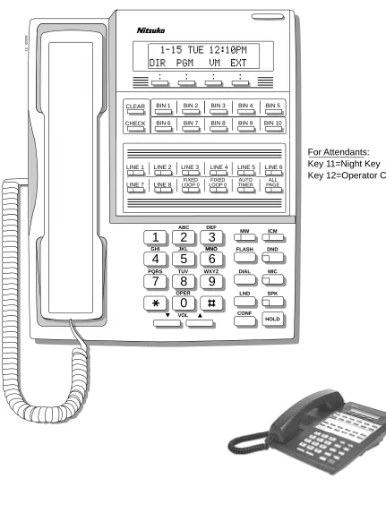
DS2000 Software Manual Chapter 1: Features ◆ 15 Figure 1: 22-Button Display Telephone (Fixed Slot)
1
2
3
4
5
6
7
8
9
0
ABC DEFMW ICM FLASH DND
DIAL MIC
LND SPK CONF
HOLD GHI JKL MNOMNO
PQRS TUV
OPER
VOL
WXYZ
CLEAR
CHECK
80000 - 21
LINE 1 LINE 2 LINE 3 LINE 4 LINE 5 LINE 6
LINE 7 LINE 8 LOOP 0FIXED LOOP 0FIXED TIMERAUTO PAGEALL BIN 1 BIN 2 BIN 3 BIN 4 BIN 5
BIN 6 BIN 7 BIN 8 BIN 9 BIN 10
For Attendants: Key 11=Night Key
Key 12=Operator Call Key
Charts and Illustrations
16 ◆ Chapter 1: Features DS2000 Software Manual
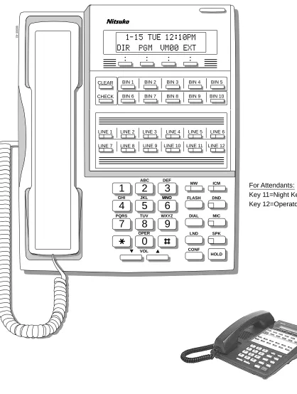
Figure 2: 22-Button Display Telephone (U Slot)
1
2
3
4
5
6
7
8
9
0
ABC DEFMW ICM FLASH DND
DIAL MIC
LND SPK CONF
HOLD GHI JKL MNOMNO
PQRS TUV
OPER
VOL
WXYZ
CLEAR
CHECK
80000 -62
LINE 1 LINE 2 LINE 3 LINE 4 LINE 5 LINE 6
LINE 7 LINE 8 LINE 9 LINE 10 LINE 11 LINE 12 BIN 1 BIN 2 BIN 3 BIN 4 BIN 5
BIN 6 BIN 7 BIN 8 BIN 9 BIN 10
For Attendants: Key 11=Night Key
Key 12=Operator Call Key
Charts and Illustrations
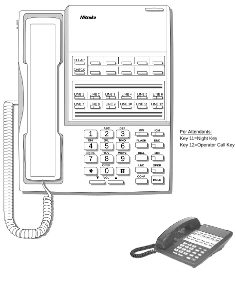
DS2000 Software Manual Chapter 1: Features ◆ 17 Figure 3: 22-Button Standard Telephone (Fixed Slot)
1
2
3
4
5
6
7
8
9
0
ABC DEFMW ICM FLASH DND
DIAL MIC
LND SPKR CONF
HOLD GHI JKL MNOMNO
PQRS TUV
OPER
VOL
WXYZ
CLEAR
CHECK
80000 - 22
LINE 1 LINE 2 LINE 3 LINE 4 LINE 5 LINE 6
LINE 7 LINE 8 LOOP 0FIXED LOOP 0FIXED TIMERAUTO PAGEALL
For Attendants: Key 11=Night Key
Charts and Illustrations
18 ◆ Chapter 1: Features DS2000 Software Manual
Figure 4: 22-Button Standard Telephone (U Slot)
1
2
3
4
5
6
7
8
9
0
ABC DEFMW ICM FLASH DND
DIAL MIC
LND SPKR CONF
HOLD GHI JKL MNOMNO
PQRS TUV
OPER
VOL
WXYZ
CLEAR
CHECK
80000 - 63
LINE 1 LINE 2 LINE 3 LINE 4 LINE 5 LINE 6
LINE 7 LINE 8 LINE 9 LINE 10 LINE 11 LINE 12
For Attendants: Key 11=Night Key
Charts and Illustrations
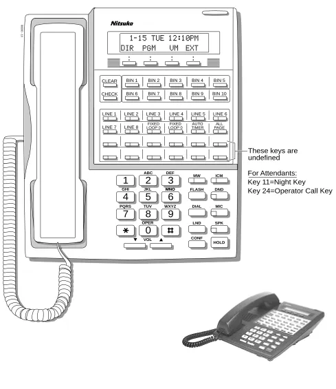
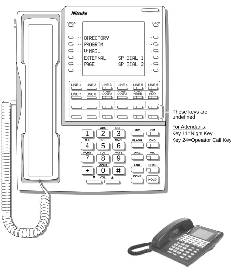
DS2000 Software Manual Chapter 1: Features ◆ 19 Figure 5: 34-Button Display Telephone (Fixed Slot)
1
2
3
4
5
6
7
8
9
0
ABC DEF
MW ICM FLASH DND
DIAL MIC
LND SPK CONF
HOLD GHI JKL MNOMNO
PQRS TUV
OPER
VOL
WXYZ
CLEAR
CHECK
80000 - 10
LINE 1 LINE 2 LINE 3 LINE 4 LINE 5 LINE 6
LINE 7 LINE 8
BIN 1 BIN 2 BIN 3 BIN 4 BIN 5
BIN 6 BIN 7 BIN 8 BIN 9 BIN 10
These keys are undefined For Attendants: Key 11=Night Key
Key 24=Operator Call Key
FIXED
Charts and Illustrations
20 ◆ Chapter 1: Features DS2000 Software Manual
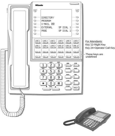
Figure 6: 34-Button Display Telephone (U Slot)
1
2
3
4
5
6
7
8
9
0
ABC DEF
MW ICM FLASH DND
DIAL MIC
LND SPK
CONF HOLD GHI JKL MNOMNO
PQRS TUV
OPER
VOL
WXYZ
CLEAR
CHECK
80000 - 64
LINE 1 LINE 2 LINE 3 LINE 4 LINE 5 LINE 6
LINE 7 LINE 8
BIN 1 BIN 2 BIN 3 BIN 4 BIN 5
BIN 6 BIN 7 BIN 8 BIN 9 BIN 10
These keys are undefined
LINE 9 LINE 10 LINE 11 LINE 12
For Attendants: Key 11=Night Key
Charts and Illustrations
DS2000 Software Manual Chapter 1: Features ◆ 21 Figure 7: 34-Button Super Display Telephone (Fixed Slot)
1
2
3
4
5
6
7
8
9
0
ABC DEFMW ICM FLASH DND
DIAL MIC
LND SPKR
CONF HOLD GHI JKL MNO
PQRS TUV
OPER
VOL
WXYZ
80000 - 23
CHECK CLEAR
LINE 1 LINE 2 LINE 3 LINE 4 LINE 5 LINE 6
LINE 7 LINE 8
These keys are undefined
FIXED
LOOP 0 LOOP 0FIXED TIMERAUTO PAGEALL
For Attendants: Key 11=Night Key
Charts and Illustrations
22 ◆ Chapter 1: Features DS2000 Software Manual
Figure 8: 34-Button Super Display Telephone (U Slot)
1
2
3
4
5
6
7
8
9
0
ABC DEFMW ICM FLASH DND
DIAL MIC
LND SPKR
CONF HOLD GHI JKL MNO
PQRS TUV
OPER
VOL
WXYZ
80000 - 65
CHECK CLEAR
LINE 1 LINE 2 LINE 3 LINE 4 LINE 5 LINE 6
LINE 7 LINE 8
These keys are undefined
LINE 9 LINE 10 LINE 11 LINE 12
For Attendants: Key 11=Night Key
Charts and Illustrations
DS2000 Software Manual Chapter 1: Features ◆ 23 Figure 9: 24-Button DSS Console
80000 - 25
300 312
301 313
302 314
303 315
304 316
305 317
306 318
307 319
308 320
309 321
310 322
Charts and Illustrations
24 ◆ Chapter 1: Features DS2000 Software Manual
Figure 10: 110-Button DSS Console (Fixed Slot)
80000 - 24
300 301 302 303 304 305 306 307 308 309
310 311 312 313 314 315 316 317 318 319
320 321 322 323 324 325 326 327 328 329
330 331 LINE 1 LINE 2 LINE 3 LINE 4 LINE 5 LINE 6 LINE 7 LINE 8
202 203 204 205 206 207 208 209 701 702
703 704 705 706 707 708 709 710 711 712
713 714 715 716 717 718 719 720 PG 0 PG 1
PK 0 PK 1
These keys are undefined
Charts and Illustrations
DS2000 Software Manual Chapter 1: Features ◆ 25 Figure 11: 110-Button DSS Console (U Slot)
80000 - 66
300 301 302 303 304 305 306 307 308 309
310 311 312 313 314 315 316 317 318 319
320 321 322 323 324 325 326 327 328 329
330 331 332 333 334 335 336 337 338 339
350 351 352 353 354 355 356 357 358 359
360 361 362 363 364 365 366 367 368 369
370 371 372 373 374 375 376 377 378 379
PAGE 1 PAGE 2 PAGE 3 PAGEALL
PARK 0 PARK 1 PARK 2 PARK 3 PARK 4 PARK 5 PARK 6 PARK 7 PARK 8 NIGHT
These keys are undefined
2-OPX Module
26 ◆ Chapter 1: Features DS2000 Software Manual
2-OPX Module
Description
LCCPU 01.00.00 Available. See see Off-Premise Extensions / On-Premise SLT Extensions on page 257.
2500 Sets / Single Line Telephones
DS2000 Software Manual Chapter 1: Features ◆ 27
2500 Sets / Single Line Telephones
Description
LCCPU 01.00.00 Available. Refer to Off-Premise Extensions / On-Premise SLT Extensions on page 257 for more.
Account Codes
28 ◆ Chapter 1: Features DS2000 Software Manual
Account Codes
Description
LCCPU 01.00.00
Alphanumeric Display
DS2000 Software Manual Chapter 1: Features ◆ 29
Alphanumeric Display
Description
The 22- and 34-Button Display Telephones have a two-line, 20-character per line alphanumeric dis-play. The first line displays the date and time (while idle) and feature status messages. The second line displays the Soft Key definitions.
The 34-Button Super Display Telephone has an eight-line, 20-character per line alphanumeric dis-play. The first line displays the data and time (while idle) and feature status messages, just like the 22- and 34-Button Display Telephones. Lines 2-8 are the comprehensive Super Display Telephone soft key definitions.
● To learn more about the display telephones, see:
see 22-Button Display Telephone (Fixed Slot) on page 15 see 22-Button Display Telephone (U Slot) on page 16 see 34-Button Display Telephone (Fixed Slot) on page 19 see 34-Button Display Telephone (U Slot) on page 20
see 34-Button Super Display Telephone (Fixed Slot) on page 21 see 34-Button Super Display Telephone (U Slot) on page 22
● To learn more about the Soft Keys, see Soft Keys on page 312.
Conditions
None
Default Setting
Enabled for all display telephones.
Programming Guide
None
Programming List
None
Other Related Features
Soft Keys (page 312)The interactive Soft keys provide users with intuitive access to the telephone’s features. The Alphanumeric Display messages help the display telephone user process calls, identify callers and customize features.
LCCPU 01.00.00
Alphanumeric Display
30 ◆ Chapter 1: Features DS2000 Software Manual
Volume Controls (page 411)
While a feature is active, pressing VOL ▲ and VOL ▼ adjusts the volume of the active feature. While a 22-Button or 34-Button Display telephone is idle, pressing VOL ▲ and VOL ▼
adjusts the display contrast. Note that 34-Button Super Display Telephones do not provide contrast adjustments. A system reset or power down returns the user-set contrast setting to a median level.
Feature Operation
Analog Communications Interface (ACI)
DS2000 Software Manual Chapter 1: Features ◆ 31
Analog Communications Interface (ACI)
Description
LCCPU 01.00.00
Alternate Attendant
32 ◆ Chapter 1: Features DS2000 Software Manual
Alternate Attendant
Description
LCCPU 01.00.00
Attendant Call Queuing
DS2000 Software Manual Chapter 1: Features ◆ 33
Attendant Call Queuing
Description
An unlimited number of callers can queue for the attendant. The callers hear ringback while they wait for the attendant to answer — not busy tone. If you have the attendant as the overflow destina-tion for Direct Inward Lines, for example, unanswered DILs will “stack up” at the attendant until they are answered
Operator Call Key
The last programmable key on an attendant telephone is permanently assigned as an Operator Call Key. When the operator has Intercom calls waiting to be answered, the calls queue under this key. The key winks (on) when calls are queued.
The Operator Call Key is a permanent assignment for all extensions assigned as operators. You can-not change this assignment. Attendant Call Queuing is a permanent, non-programmable feature.
Conditions
None
Default Setting
At attendant (extension 300 by default), key 12 (on 22-button) or key 24 (on 34-button) is an Oper-ator Call Key.
Programming Guide
None
Programming List
None
Other Related Features
Attendant Position (page 35)Assign system attendants.
Off-Hook Signaling (page 255)
The Operator Call Key activates off-hook signaling.
Ringing Line Preference (page 302)
Ringing Line Preference will not answer a call ringing the Operator Call Key.
Voice Mail (page 396)
●TRF transfers to the attendant from the Voice Mail Automated Attendant flash the Operator Call key and the Ring Indicator lamp. The call does not flash a line/loop key. (Note that Ringing Line Preference will not pick up a call ringing the attendant’s Call Queue key.) LCCPU 01.00.00
Available. LCCPU 02.00.00
Attendant Call Queuing
34 ◆ Chapter 1: Features DS2000 Software Manual
●UTRF transfers to the attendant from the Voice Mail Automated Attendant flash the trunk’s line/loop key and the Ring Indicator lamp.
Feature Operation
To answer a call flashing the Operator Call Key:
1. Press the flashing Operator Call Key.
Attendant Position
DS2000 Software Manual Chapter 1: Features ◆ 35
Attendant Position
Description
The attendant is the focal point for call procesing within the system. The system can have up to four attendants. In addition to the features of a standard keyset, the attendant also has the following unique capabilities (refer to the respective feature for details):
● Attendant Call Queuing (page 33)
Incoming Intercom calls from co-workers queue for the attendant. The callers never hear busy tone.
● Barge In (Intrusion) (page 48)
The attendant can break into another extension user’s established call. This option is enabled in the attendant’s Class of Service (COS 1).
● Direct Trunk Access (page 129)
Direct Trunk Access lets the attendant user dial a code to access an individual trunk. This option is enabled in the attendant’s Class of Service (COS 1).
● Forced Trunk Disconnect (page 167)
In an emergency, the attendant can release (disconnect) another user’s active trunk call. This option is enabled in the attendant’s Class of Service (COS 1).
● Night Service / Night Ring (page 250)
An attendant with a Night key can put the system in the night mode. This option is enabled in the attendant’s Class of Service (COS 1).
● Removing Trunks and Extensions From Service (page 293)
The attendant can remove problem trunks from service —then return them to service once the problem is corrected. This option is enabled because the attendant has Direct Trunk Access enabled in their Class of Service (COS 1).
● Trunk (Line) Queuing / Trunk Callback (page 384)
The attendant can Camp On (queue) for a busy trunk. This option is enabled in the attendant’s Class of Service (COS 1).
The attendant should use a 34-Button Display or 34-Button Super Display Telephone. In addition, most attendants should find a 24-Button or 110-Button Direct Station Selection (DSS) Console helpful when processing calls.
Conditions
Ringing Line Preference will not pick up a call ringing the attendant’s Call Queue key.
Default Setting
The system has one operator assigned to extension 300. LCCPU 01.00.00
Available. LCCPU 02.00.00
Attendant Position
36 ◆ Chapter 1: Features DS2000 Software Manual
Programming Guide
Step-by-step guide for setting up Attendant Position
Step 1: Install a 34-Button Display or 34-Button Super Display telephone for the attendant.
• A 24-Button or 110-Button DSS Console will also help the attendant process calls more quickly.
Step 2: Should the system have more than one attendant?
• In Program 0301 - Number of Operators (page 426), enter 2-4.
• In Program 0301 - Operator 1 Extension (page 426), Program 0301 - Operator 2
Exten-sion (page 426), Program 0301 - Operator 3 Extension (page 426), and Program 0301 - Oper-ator 4 Extension (page 426), assign the operOper-ator
extensions.
• In Program 1802 - Extension’s Operator (page 515), assign an operator to each extension.
• In Program 0301 - Number of Operators (page 426), enter1.
• In Program 0301 - Operator 1 Extension (page 426), assign the system operator’s exten-sion (normally 300).
• In Program 1802 - Extension’s Operator (page 515), assign each extension to the operator (normally 300).
Step 3: While busy on a call, should the attendant be audibly notified of incoming calls?
• Program 1802 - Off-Hook Signaling for CO Calls
(page 514), at the attendant’s extension enter 1 for Call Waiting beeps, 2 for off-hook ringing.
• Program 1802 - Off-Hook Signaling for CO Calls
(page 514), enter 0 for the attendant’s extension.
Step 4: Should the first digit an extension user dials to reach an operator be 0 (e.g., 0 for single operator systems, 01-04 for multiple operator systems)?
• In Program 0501 - Digit 0 Options (page 447), be sure this option is left at its default setting
(Func-tion Type = 1 and Expected Digits = 2).
• In Program 0501 - Digit 0 Options (page 447), exchange the digit 0 settings with the new digit.
Attendant Position
DS2000 Software Manual Chapter 1: Features ◆ 37
Programming List
Note: Designating an extension as an operator in Program 0301 automatically assigns Class of Service 01 to that extension. If you change your operator setup and make an operator a “normal” extension, be sure to go back and manually reassign a new Class of Service (2-15) to that extension. Note that the attendant’s Class of Service options are fully customizable.
Program 0301 - Number of Operators (page 426)
Specify the number of operators in the system (1-4).
Program 0301 - Operator 1 Extension (page 426)
Assign the 1st operator’s extension number. Be sure you have entered the correct number in the Number of Operators option above.
Program 0301 - Operator 2 Extension (page 426)
Assign the 2nd operator’s extension number. Be sure you have entered the correct number in the Number of Operators option above.
Program 0301 - Operator 3 Extension (page 426)
Assign the 3rd operator’s extension number. Be sure you have entered the correct number in the Number of Operators option above.
Program 0301 - Operator 4 Extension (page 426)
Assign the 4th operator’s extension number. Be sure you have entered the correct number in the Number of Operators option above.
Program 0501 - Digit 0 Options (page 447)
Assign the digit(s) the system will use for operator access (normally 0 and 01-04). Do not change the Expected Digits entry for the digit 0.
Program 1802 - Extension’s Operator (page 515)
Assign the extension’s operator (300-395). This is the co-worker the extension user reaches when they dial 0.
Program 1802 - Off-Hook Signaling for CO Calls (page 514)
To have the system audibly alert the operator when trunk calls are waiting, assign an exten-sion’s Off-Hook Signaling options for trunk calls (0 = no Off-Hook Signaling, 1 = Call Wait beeps over speaker, 2 = Off hook ringing.
Other Related Features
Barge In (Intrusion) (page 48)
Since the attendant is never busy, Intercom callers cannot Barge In on an attendant.
Call Waiting / Camp-On (page 66)
Since the attendant is never busy, Intercom callers cannot Camp On to an attendant.
Callback (page 69)
Since the attendant is never busy, Intercom callers cannot leave a Callback for an attendant.
Class of Service (page 93)
By default, the system assigns Class of Service 1 to the attendant. This provides the attendant with Alternate Attendant, Barge In, Call Forwarding Off Premise, Direct Trunk Access, Forced Trunk Disconnect, Night Service, and Trunk Queuing (Camp On) capability.
Do Not Disturb (page 137)
The attendant can have Do Not Disturb. In addition, pressing DND at the attendant activates the night mode for any trunks directly terminated to the attendant.
Group Ring (page 175)
System operators will not ring for Ring Group calls.
Intercom (page 214)
Designate each extension’s operator.
Monitor / Silent Monitor (page 242)
Attendant Position
38 ◆ Chapter 1: Features DS2000 Software Manual
Privacy (page 277)
Since the attendant is never busy for Intercom calls, the attendant always has Privacy enabled.
Removing Trunks and Extensions From Service (page 293)
Normally, the attendant should be able to remove extensions and trunks from service.
Voice Mail (page 396)
●TRF transfers to the attendant from the Voice Mail Automated Attendant flash the Operator Call key and the Ring Indicator lamp. The call does not flash a line/loop key. (Note that Ringing Line Preference will not pick up a call ringing the attendant’s Call Queue key.)
●UTRF transfers to the attendant from the Voice Mail Automated Attendant flash the trunk’s line/loop key and the Ring Indicator lamp.
Feature Operation
To call the attendant:
1. Press ICM.
2. Dial 0.
This calls the attendant assigned to your extension. If your system has multiple atten-dants, you can reach them by dialing 01-04.
Dial tone.
ICM and SPK on.
Two beeps.
Automatic Call Distribution (ACD)
DS2000 Software Manual Chapter 1: Features ◆ 39
Automatic Call Distribution (ACD)
Description
LCCPU 01.00.00
Automatic Fault Reporting
40 ◆ Chapter 1: Features DS2000 Software Manual
Automatic Fault Reporting
Description
LCCPU 01.00.00
Automatic Handsfree
DS2000 Software Manual Chapter 1: Features ◆ 41
Automatic Handsfree
Description
Automatic Handsfree allows a keyset user to place or answer a call Handsfree by just pressing a key — without lifting the handset or pressing SPK first. If enabled, the system provides Automatic Handsfree for:
● Call Coverage Keys
● Central Office Calls (line and loop calls)
● Group Call Pickup keys
● Hotline Keys
● Intercom (ICM key)
● Last Number Redial (LND key)
● Paging keys
● Park keys
● Personal Speed Dial bin keys
● Personal and System Speed Dial keys
The system always provides Automatic Handsfree for:
● Dial Number Preview
● Directory Dialing
Conditions
None
Default Setting
Enabled
LCCPU 01.00.00
Available. LCCPU 02.00.00
Automatic Handsfree
42 ◆ Chapter 1: Features DS2000 Software Manual
Programming Guide
Programming List
Program 0201 - Automatic Handsfree (page 424)
Enter Y to enable Automatic Handsfree system-wide.
Program 1802 - Automatic Handsfree (page 514)
Enter Y to enable Automatic Handsfree.
Step-by-step guide for setting up Automatic Handsfree
Step 1: IShould an extension be able to use Automatic Handsfree?
• In Program 0201 - Automatic Handsfree (page 424), enter Y to enable Automatic Hands-free system wide.
• In Program 1802 - Automatic Handsfree (page 514), enter Y to enable Automatic Hands-free for the extension.
• In Program 1802 - Automatic Handsfree (page 514), enter N to enable Automatic Hands-free for the extension.
Step 2: Do you want to disable Automatic Handsfree for all extensions system-wide?
• In Program 0201 - Automatic Handsfree (page 424), enter Y to enable Automatic Hands-free for all extensions system-wide.
• In Program 0201 - Automatic Handsfree (page 424), enter N to disable Automatic Hands-free for all extensions system-wide.
If yes
If no
If yes
Automatic Handsfree
DS2000 Software Manual Chapter 1: Features ◆ 43
Other Related Features
Central Office Calls, Placing (page 83)
With Automatic Handsfree, an extension user can press a line key to place a trunk call without first lifting the handset or pressing SPK. Users without Automatic Handsfree can preselect a line key before lifting the handset or pressing SPK.
Handsfree and Handsfree Answerback (page 182)
Process calls using the speaker and microphone in the telephone (instead of the handset).
Headset Compatibility (page 186)
While in the headset mode, Automatic Handsfree simplifies answering trunk calls.
Line Keys (page 225)
Automatic Handsfree allows the keyset user to answer a call ringing a line key without lifting the handset; they just press the line key instead.
Loop Keys (page 229)
Automatic Handsfree allows the keyset user to answer a call ringing a loop key without lifting the handset; they just press the loop key instead.
Feature Operation
Automatic Ring Down
44 ◆ Chapter 1: Features DS2000 Software Manual
Automatic Ring Down
Description
LCCPU 01.00.00
Automatic Route Selection
DS2000 Software Manual Chapter 1: Features ◆ 45
Automatic Route Selection
Description
LCCPU 01.00.00
Not available. LCCPU 02.00.00
Background Music
46 ◆ Chapter 1: Features DS2000 Software Manual
Background Music
Description
Background Music (BGM) sends music from a customer-provided music source to speakers in key-sets. If an extension user activates it, BGM plays whenever the extension is idle. Incoming calls and Paging announcements temporarily override (turn off) Background Music.
Background Music requires a customer-provided music source. You connect the Background Music music source to pins 3 and 6 in the CPU’s 8-pin mod jack. Using the DS2000 installation cable, these pins punch down as 3 and 4. The music source you use for Background Music must be com-patible with the following specifications:
Note:
In accordance with U.S. copyright law, a license may be required from the America Society of Composers, Authors and Publishers (ASCAP) or other similar organizations, if radio, television broadcasts or music other than material not in the public domain are transmitted through the Back-ground Music feature of telecommunications systems. Nitsuko America hereby disclaims any lia-bility arising out of the failure to obtain such a license.
Conditions
None
Default Setting
Enabled system-wide and at each extension.
Programming Guide
LCCPU 01.00.00
Available. LCCPU 02.00.00
Broadcast music through the telephone speaker for a more pleasing work environment.
Table 3: Music Source Specifications
Input Impedance 10K Ohms
Relative Input Level +18 dBr (+/- dBr) at 1.0 kHz
Step-by-step guide for setting up Background Music
Step 1: Should Background Music be enabled system-wide?
• In Program 0201 - Background Music (page 425), enter Y to enable Backgorund Music system-wide.
• Connect the music source to the CPRU music ter-minals.
Background Music
DS2000 Software Manual Chapter 1: Features ◆ 47
Programming List
Program 0201 - Background Music (page 425)
Enter Y for this option to enable Background Music system-wide.
Program 1802 - BGM (page 515)
Enter Y to enable Background Music at the extension.
Other Related Features
Do Not Disturb (page 137)DND does not affect the operation of Background Music.
Headset Compatibility (page 186)
Background Music plays in the headset when the extension is in the headset mode.
Music on Hold (page 245)
Background Music and Music on Hold share the same music source.
Off-Premise Extensions / On-Premise SLT Extensions (page 257)
Background Music is not available to On- and Off-Premise extensions.
Feature Operation
To turn Background Music on and off:
1. Do not lift handset or press SPK. 2. Press HOLD.
• In Program 0201 - Background Music (page 425), enter N to disable Backgorund Music system-wide.
Step 2: Once enabled system-wide, should individual extension have Background Music?
• In Program 1802 - BGM (page 515), enter Y to enable Backgorund Music for the extension.
• In Program 1802 - BGM (page 515), enter N to disable Backgorund Music for the extension.
Step-by-step guide for setting up Background Music
If no
If yes