SCOPE
These specifications apply to the TEAC MT-2ST/45S2 Streaming Cassette Magnetic Tape Unit (hereinafter referred to as the MTU).
MAGNETIC TAPE USED
This unit uses the TEAC CT-500H high density magnetic tape cassettes (hereinafter referred to as the cassette, tape, or cassette tape), or compatible magnetic tape approved between the customer and TEAC.
CONFIGURATION
The MT-2ST/45S2 consists of the MTU and accessories sold separatel~. An interface controller (PCBA IC) is incorporated in the MTU.
MTU Types and Major Functions
Name Part No. Tape speed Head
MT-2ST/45S2-27 19305060-27 90 ips Ferrite head
CONSTRUCTION
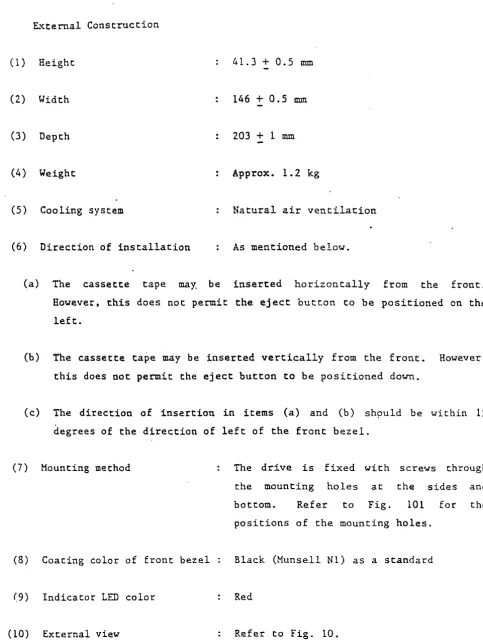
~~ternal Construction
(1) Height 41.3
+
0.5 mID(2) Width 146
+
0.5 mID(3 ) Depth 203
+
1 mID(4 ) Weight Approx. 1. 2 kg
(5 ) Cooling system Natural air ventilation
(6) Direction of installation As mentioned below.
(a) The casSette tape may. be inserted horizontally from the front. However, this does not permit the eject button to be positioned on the left.
(b) The cassette tape may be inserted vertically from the front. However, this does not permit the eject button to be positioned down.
(c) The direction of insertion in items (a) and (b) sh"uld be within 15 degrees of the direction of left of the front bezel.
(7) Mounting method The drive is fixed with scre'N'S through
the mounting holes at the sides and bottom. Refer to Fig. 101 for the
positions of the mounting holes.
(8) Coating color of front bezel Black (Munsell Nl) as a standard
(9) Indicator LED color Red
JI Interface connector J2 Po~er supply connector
(PCBA DC)
r
(PCBA IC)\39.7'0.5
..
,
.
L'
~L _ _ _ _
+ ___
I
JP
I\46tO.5
149;!:O.5
r
1/
t" 1 ~-'
~-+-~
1 2 3 4
I I
o
..
'"
o...
~'"
.;..
'"
~..
..,
o'"
-..
'"
....-PCBA DC
TaoDed .ountlnQ holes
4-16-32
5 deeD (hoth sideS)
TaDDed .0untiM holes
4-~3
5 deeD (hatton I
TaDDed moun tI nQ ho I es
4-N3 5 deeD !hath s Ides I
r
Indicatorr
cassette Insertion slot(~Ith doorl I
~
II
III
II ' II III I
i
I
e
\
I
0
~
front bezelI
l
Eject hutton F i q. 10 NTU External Viell4t. 3!0.
-,
1_ .J
II
33. S±O. 5
12.9'0.5
01
Component
~--~~-- surface
PCBA I C
0>
....
o
••
...
i
ItO,o.s . !21.a!0.s42. 8:!:O. 5
ENVIRONMENTAL CONDITIONS
(1) Ambient temperature
(a) In operation
(b) Nonoperating
(2) Temperature gradient
(a) In operation
(b) Nonoperating
(3) Relative humidity
(a) In operation
(b) Nonoperating
(4) Vibration
(a) In operation
(b) During transportation
(S) Shocks
(a) In operation
(b) During transportation
(6) Transport condition
s·C to 4S·C
-2s·C to 60·C
Less than ls·C/hour (noncondensation)
Less than 30·C/hour (noncondensation)
20 to 80% (noncondensation)
Maximum wet-bulb temperature ••. 26·C
10 to 90% (noncondensation)
Less than 0.2G (5 to 50 Hz)
Less than 2G (5 to 50 Hz)
Less than SG (less than 10 msec)
Less than 40G (less than 10 msec)
The general rule level II of the proper package goods test method in JIS-Z0200 is satisfied when the specified packing case
OPERATIONAL CHARACTERISTICS
Tape Drive System Operational Characteristics
(1) Tape speed
(2) Long-term speed variation (LSV)
(3) Instantaneous speed variation (ISV)
Control Characteristics
(1 ) Average recording/reading
speed
(2) Block length
(3) Buffer memory
(4) Retry count at recording
(5) Retry count at reading
(6) Repositioning time
(7) Maximum rewinding tice
90 ips (2286
mm/
sec)+4%
+4%
Nominal 86.3 K bytes/sec. (in streaming condition)
512 bytes
50 blocks
16 max.
16 max.
Approx. 1 second
Interface Characteristics
(1) Interface In compliance ~ith SCSI
(ANSI XJ.131-1986)
(2) Data transfer capability (transfer speed in case the host system responds in the shortest time)
(a) At recording
(b) At reading
Reliability
(1 ) Mean time between failures (MTBF)
(2) Mean time to repair (MTTR)
(3) Error rate
(a) Soft error
(b) Hard error
600 K bytes
I
s600 K bytes/s
10,000 POH or more (Duty cycle: 4.2%)
Less than 30 min.
Once per 108 bits
SCOPE
These Specifications apply to the TEAC MT-2ST/45D Streaming Cassette Magnetic Tape Unit (hereinafter referred to as the MTU).
MAGNETIC TAPE USED
This unit uses TEAC CT-500H high density magnetic tape cassettes (hereinafter referred to as the cassette, tape or cassette tape), or comparable magneti~ tape approved between the customer and TEAC.
CONFIGURATION
The MT-2ST/45D consists of the MTU and accessories sold separately.
An
interface controller (PCBA Ie) is incorporated in the MTU.
MTU Types
Name Commodity No. Tape apeed Head
MT-2ST/ ~5D - 1~ 19305060- 1~ 90ips Perrite head
Accessories
CONSTRUCTION
External Construction
(1) Height
(2) Width
(3) Depth
(4) Weight
(5) Cooling system
(6) Direction of installation
4L3
+
0.5 mm146 + 0.5 mm
203
+
1 mm (L~cluding the interface connector projection)Approx. 1. 2 kg
Natural air ventilation.
As mentioned below.
(a) The cassette tape may be inserted horizontally from the front. However, this does not permit the eject button to be positioned on the left.
(b) The cassette tape may be inserted vertically from the front. However, this does not permit the eject button to be positioned down.
(cl The direction of insertion in items (a) and (b) should be within 15 degrees of the direction of left of the front bezel.
(7) Mounting method
(8) Coating color of front bezel
(9) Indicator LED color
(10) External view
The drive is fixed with screws through the mounting holes a t the sides and bottom. (Refer to Fig. 101.)
Black (Munsell N1)
Red
.,
~I Interrace connector ~1 pover suooly connector (PC SA DC)
~ (PCSA IC)
{,
\ . IeY slot
139. HO. 5
27.4!J.S 43.6:0.5
/
-I\l
7
so40
i
't
i'
II
I II"
Tr~,"
I
~~L_+_J
I Z 3 4 I
I '
,
...,
,
1
---~,I .J
,I
(c
P.
II
r' (
I J
I r I
lQ ___
LJ
C)
I,
I )
~
I I
110
I01
II
~
,
II I
' 0
J
I
,
IC)
I I I
I I
1:::=:1
,...,
l (
~
J
.,
I
1 1
14610.5
149tO. 5
~
.,
U1 M0
:;:
..
'"
'"
r-V
.r-'"
0..
.,
r-.,
,
'"
~0
..
..
'"
It1
..:
~PCBA DC
1400ld ~ountln9 hall!
4-16-31 5 deep (both IIdW
Taooed
.ountlnt hOles I-Wl
S dIeD
(bottom)
Taoold lOunt I n9 ho 1 IS
4-W3 5 delo
(both sides)
Indicator Casselle Inserllon slot (_Ith door)
II
III II
l
'LI_
Jill
Front bezel EJact button
(F 19. 101)
MTU ExternalVlev
41. HO.
~
33. 5tO. 5
12 910.5
comconent
surfacePCB A IC
I I
-.~H-1I---r
I I
ID
o
..
N'"
..
In o..
.,
...
.,
1010. 5
1. 8±0. 5
42.810.5
ENVIRONMENTAL CONDITIONS
(1) Ambient temperature
(a) In operation
(b) Nonoperating
(2) Temperature gradient
(a) In operation
(b) Nonoperating
(3) Relative humidity
(a) In operation
(b) Nonoperating
(4) Vibration
(a) In operation
(b) During transportation
(5) Shocks
(a) In operation
(b) During transportation
-2S·C _ 60·C
Less than lS·C/hour (concondensation)
Less than 30·C/hour (noncondensation)
20 _ 80% (noncondensation) Haximum wet-bulb temperature '" 26·C
10 _ 90% (noncondensation)
Less than 0.2G (S _ SO Hz)
Less than 2G (5 _ 50 Hz)
Less than 5G (less than 10 msec)
OPERATIONAL CHARACTERISTICS
Tape Drive System Operational Characteristics
(1) Nominal tape speed
(a) MT-2ST/ ~5D-
a
(2) Long-term speed variation (LSV)
(3) Instantaneous speed variation (ISV)
- Control Characteristics
(1) Average data transfer speed
(a) MT-2ST/ ~5D-
a
(2) Block length
(3) Buffer memory
(4) Retry count at recording
(5) Retry count at reading
90 ips (2286 mm/sec)
Nominal 86.3K bytes/sec
512 bytes
3 buffers
16 max.
(6) Repositioning time
(a) MT-2ST/ ~5D-14
(7) Maximum rewinding time
Reliability
(1) Mean time between failure (MTBF)
(2) Mean time to repair (MTTR)
(3) Error rate
(a) Soft error
(b) Hard error
Approx. 1 sec
Approx 70 seconds
: 10. 000 POH or more ( Du ty cycle: 4.2% )
Less than 30 min.
Once per 10· bits
GENERAL"
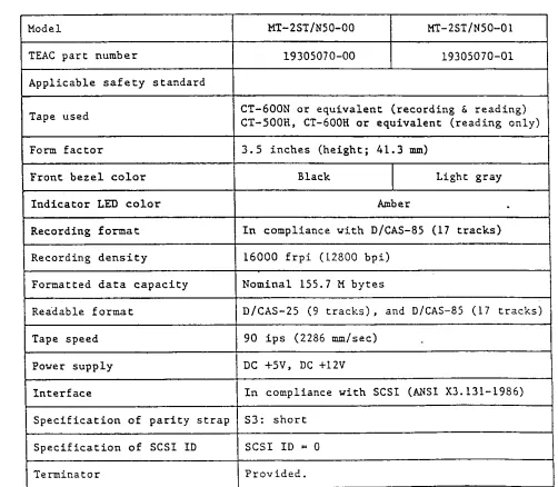
The present specifications apply to the TEAC NT-2ST/N50 Streaming Cassette Magnetic Tape Unit (hereinafter, referred to as the MIU). Table 1 shows the general specifications of the" MTU.
Model MT-2ST/N50-00 MI-2ST/N50-01
TEAC part number 19305070-00 19305070-01
Applicable safety standard
Tape used CT-600N or equivalent (recording CT-500H, CT-600H or equivalent (reading only)
&
reading)Form factor 3.5 inches (height; 41. 3 mm)
Front bezel color Black Light gray
Indicator LED color Amber
.
Recording format In compliance with D/CAS-85 (17 tracks) Recording density 16000 frpi (12800 bpi)
Formatted data capacity Nominal 15S.7 M bytes
Readable format D/CAS-25 (9 tracks), and a/CAS-8S (17 tracks)
Tape speed 90 ips (2286 mm/sec)
Power supply DC +5V, DC +12V
Interface In compliance with SCSI (~~SI X3.131-1986) Specification of parity strap 53: short
Specification of SCSI 10 SCSI 10 = 0
Terminator Provided.
(1)
( 2)
(3)
( 4)
(5)
(6)
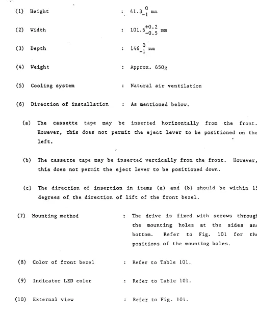
External Construction
Height
Width
Depth
Weight
Cooling system
Direction of installation
146 0
-1 rom
Approx. 650g
Natural air ventilation
As mentioned beloy.
(a) The cassette tape may be inserted horizontally from the front.
Hoyever, this does not permit the eject lever to be positioned on the
left.
(b) The cassette tape may be inserted vertically from the front. Hoyever,
this does not permit the eject lever to be positioned doYn.
(c) The direction of insertion in items (a) and (b) should be Yithin 15
degrees of the direction of lift of the front bezel.
(7) Mounting method
(8) Color of front bezel
(9) Indicator LED color
(10) External viey
The drive is fixed yith screys through
the mounting holes at the sides and
bottom. Refer to Fig. 101 for the
positions of the mounting holes.
Refer to Table 101.
Refer to Table 101.
J2 Pover supply
JI Interrace connector
r
(~~~!~~~{
r
(PCBA Cl)94 >0 ••
I
<18.2 >0. 5i
I
I
37 to .• 49
'0
r
I
T' •
\1
.
I
____ 1L ____________
I ?---r----~ J4 3 2 1
to
-
JI r
I .
t.j [
r---_
I---.
0
11
f----.
,
1 \ I
I D I 1 I I a 1 I I
I
\---'
,.-1 1 1 1 IlP
I I~
1 I II
1----,J I
~
'" 0 ";'
.; co
..
q 0...
...
V
I--"'
.;
..
...
..,
PCBA MO
lapped .ounting holes
~-~l \
5 de" \ (both sides)
ra,"d
Boun ti nq ho I es
~-~l 5 deel
(both sides)
lapped .ountinq holes
"=~=~======~;;~;;:;;;~F==ti
4-#6-31~ 5 dee,
l
(both sides)_~J
r'
--+ O. 2
101.6-0.
, a .
103.9 -0 .•
cassette Insertion slH (~ith door)
~Indicator
Fran tbelel~
FrontTurn direction
rna n: e r
lever
(Fig. 101) MTU External Vie",
a
41.
3-I
J 1
PCB A CL
I III
5 to. ,~.
..
ENVIRONMENTAL CONDITIONS
·"(1) Ambient tempera,ture
(a) In operation
(b) During stor~ge or transportation
(2) Temperature gradient
(a) In operation
(b) During storage or transportation
(3) Relative humidity
(a) In operation
,
(b) During storage or transportation
(4) Vibration
(a) In operation
(b) Nonoperating
(5) Shocks
(a) In operation
S·c to 4S·C
-2S·C to 80·C
Less than lS·C/hour (non-dewing)
Less than 30·C/hour (non-dewing)
20 to 80% (non-dewing)
Maximum wet-bulb temperature; 26·C
10 to 90% (non-dewing)
Less than o.se (5 to 100 Hz 3 minutes sweep) Less than 0.2Se (100 to 500 Hz 3 minutes sweep)
Less than 2G (5 to SO Hz 3 minutes sweep)
(b) Nonoperating
(6) Transport conditions
Less than SOG (less than 10 msec)
The general rule level II of the proper package goods test method in JIS-Z0200 is satisfied, when specified packing
OPERATIONAL CHARACTERISTICS
Tape Drive System Operational Characteristics
(1) Tape speed
(2) Long-term speed variation (LSV)
(3) Instantaneous speed variation (ISV)
(4) Maximum rewinding time
(5) Repositicning time
Control Characteristics
(1) Recording/reading data format
(a) Recording and reading
(b) Reading only
(2) Average recording/reading speed
(a) D/CAS-85 (17 tracks)
(b) D/CAS-25 (9 tracks)
(3) Block length
(4) Buffer memory
90 ips (2286 mm/sec)
+4%
+47.
Approx. 80 sec (with CT-600N used)
Approx. 1 sec
In compliance with D/CAS-85 (17 tracks)
In compliance with D/CAS-25 (9 tracks)
Nominal 116.2 K bytes/sec (in streaming condition)
Nominal 86.3 K bytes/sec (in streaming condition)
512 bytes (fixed)
(5) Retry count at recording
(6) Retry count at reading
(7) Timing margin check (a t recording)
Interface Part
(1) Interface
Hax. 15 times
Hax. 16 times
Center position :0.125t (t = 1 bit interval)
In compliance "ith SCS1 (A.'lSI X3.131 -1986)
(2) Data· transfer capacity (average transfer speed in case the host system responds in the shortest time)
(a) At recording
(b) At reading
Reliability
(1) Hean time between failures (HTBF)
(2) Hean time to repair (MTTR)
(3) Error rate
(a) At D/CAS-85 format reading
i) Soft error ii) Hard error
500 K bytes/sec
500 K bytes/sec
10,000 POH or more
Less than 30 min
GENERAL
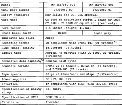
The present specifications apply to the TEAC MT-2ST/F50 Streaming Cassette Magnetic Tape Unit (hereinafter, referred to as the MTU). Table 101 shows the general specifications of the MTU.
Model MT-2ST/F50-000 MT-2ST/F50-001
TEAC part number 19305080-00 19305080-01
Safety standards Now filing for UL, CSA approval
Tape used CT-600F or equivalent (write & read) CT-500H, CT-600H, CT-600N or equivalent (read only)
Form factor 3.5 inches (height; 41.3mm)
Front bezel color Black Light gray
Indicator LED color Amber
Recording format In compliance with D/CAS-103 (21 tracks)*l Flux (Data) density 48,000ftpi (38,400bpi)
.
Backup time Approx. 45 minutes (with CT-600F, 21 tracks,streaming)
Formatted data capacity" Nominal 600M bytes
Readable formats D/cAS-25 (9 tracks), D/CAS-85 (17 tracks), and D/CAS-103 (21 tracks)
Tape speeds 90ips (2,286mm/sec) and 60ips (1,524mm/sec)
Power supplies DC +5V I DC +l2V
Interface In compliance with SCSI (ANSI X3.131-1986) Specification of parity 53: short
strap
Specification of SCSI SCSI ID ; 0
Terminator Provided
Notes: 1. "D/CAS" in *1 is an abbreviation for "The Working Group for Data Cassette Drive Compatibility" and the XX in D/cAS-XX indicates the number of a standard approved by the group.
2. The formatted capacity in *2 is not a guaranteed value in the most hostile environment. A capacity of 600M bytes may not be achieved depending on the tape used and operating conditions. For details, refer to the instructions of the
TEAC MT-2ST/F50.
CONSTRUCTION
External Construction
(1) Height 41.3mm (1.626 in), Max.
(2) Width 101.6mm (4.000 in), Max.
(3) Depth 146.0mm (5.750 in), Max.
(4) Weight Approx. 660g (Approx. 1.455 lbs)
(5) Direction of installation: As mentioned below.
(a) The cassette tape may be inserted horizontally from the fro~t.
However, this does not permit the indicator to be positioned on the right.
(b) The cassette tape may be· inserted vertically from the front. However, this does not permit the indicator to be positioned at the top.
(c) The direction of insertion in items (a) and (b) should be within 10 degrees of the direction perpendicular to the front bezel.
(6) Mounting method
(7) Color of front bezel
(8) Indicator LED color
(9) External view
The drive is fixed with screws through the mounting holes at the sides and bottom.
Refer to Fig.101 for the positions of the mounting holes.
Refer to Table 101.
Refer to Table 101.
J2 PO'w'er supply connector (peBA Fel)
r
i 94:0 . •
r
7
.as .2iO. 5J 1
I / ;
I /
:~
I
!~
I
r;
;.---f----~
f~i~~~,---JI
~
II
..-
...iInterface connectol (peBA Fel)
peBA FIAD
1'1
It It It -n It It It!!/P.d It
mounting hOles II
o
41.
3-37.1iO.s
.a.2:to.s
JI
PCBA fCl
,3
r~--~F_~_-l ~t--~tI:1---r o~
J11
~.
(0\1
I::
~ ~
'-.'---'"
• !
:
...
Hl \ It
(bo:n
6::~es) ~
~
.;
. I' ~ I
r··...
II \ !t II : I I Iamd
IOunling hales Hl
5 6."
(bolh sides)
~
__ J,: :
l~j ',~~
v'-i
k-~
li~J
~
1.",d~
~'==~==L-==:-=-=-=
--=~. ~-';:::;;!S;:::j;:"'~=t
Dounl;og ho 4-16-l2 I isl
_ 101.6-g.5
5 6."o
103 . 9 -0. 6
cassette insect ion "'"\
slot (vllh door) \ ,
\
II
[i
11\
JIO
1
'---
--Jr
GJ
\
[:1J "
\
bezel LEiecI
(bOlh ,;6.,)
button
(Fig.10l) MTU External view
., o
'"
I~I ~
5'0.'
I
,o~s
. .a2.9-0 5
!
ENVIRONMENTAL CONDITIONS
(1) Ambient temperature
(a) In operation (b) During storage or
transportation
(2) Temperature gradient
(a) In operation (b) During storage or
transportation
(3) Relative humidity
(a) In operation
(b) During storage or transportation
(4) Vibration
(a) In operation (b) Non-operating
(5) Shocks
(a) In operation (b) Non-operating
5 - 45°C (41 - 113°F)
-25 - 60°C (-13 - 140°F)
15°C (27°F)/hour or less (non-condensing)
30°C (S4°F)/hour or less (non-condensing)
20 - 80% (non-condensing)
Maximum wet-bulb temperature shall be 26°C (79°F)
10 - 90% (non-condensing)
Maximum wet-bulb temperature shall be 45°C (113°F)
O.SG or less (5 - 500Hz, sweeps at 1 oct/min.) 2G or less (5 - 50Hz, sweeps at 1 oct/min.)
SG or less (llmsec or less) SOG or less (llmsec or less)
OPERATIONAL CHARACTERISTICS
Tape Drive System Operational Characteristics
(1) Tape speed
(a) D/CAS-103 write/read 60ips (1,524mm/sec)
(b) D/CAS-25 and D/CAS-85 read: 90ips (2,286mm/sec)
(2) Long-term speed variaiton
(LSV) : ±3%
(3) Instantaneous speed
variation (ISV)
(4) Maximum rewinding time
(a) CT-600F
(b) CT-600N or CT-600H
±4%
Approx. 135sec
Approx. 85sec
(5) Repositioning time (CT-600F)
(a) Write (TRACK 00)
(b) Write and read
Approx. 3.5sec
(other than TRACK 00): Approx. 2sec
Control Characteristics
(1) Write/read data format
(a) Write and read
(b) Downward read
In compliance with D/CAS-103 (21 tracks)
In compliance with D/CAS-85 (17 tracks)
In compliance with D/CAS-25 (9 tracks)
(2) Average data transfer rate in streaming operation
(b) O/CAS-8S (17 tracks)
(c) O/CAS-2S (9 tracks)
(3) Block length on tape
(4) Buffer memory
(S) Retry count at write
(6) Retry count at read
(7) Timing margin check
(at write)
Interface Part
(1) Interface
(2) Maximum data transfer rate
(a) Write
(b) Read
Nominal 122.SK bytes/sec
Nominal 86.3K bytes/sec
1,024 bytes (O/CAS-l03)
S12 bytes (O/CAS-8S, O/CAS-2S)
Max. lS times
Max. 16 times
Center position
±O
.12St (t 1 bit interval)In compliance with SCSI (ANSI X3.131-1986)
S60K bytes/sec
S60K bytes/sec
(3) Block length at SCSI command
Reliability
(1) Mean time between failures (MTBF)
: S12 bytes (D/CAS-l03, O/CAS-8S, O/CAS-2S)
10,000 POH or more
~
S2 SI SO SCSI ID0 0 0 0
1 0 0 1
2 0 1 0
3 0 1 1
4 1 0 0
5 I 0 1
6 1 1 0
7 I 1 1
Note: (1) There are 2 strap states: 1: OPEN and 0: SHORT