Volume 2006, Article ID 97676, Pages1–14 DOI 10.1155/ASP/2006/97676
A Fast Sphere Decoding Algorithm for
Space-Frequency Block Codes
Zoltan Safar,1, 2Weifeng Su,1, 3and K. J. Ray Liu1
1Department of Electrical and Computer Engineering, A. James Clark School of Engineering,
and Institute for Systems Research, University of Maryland, College Park, MD 20742, USA
2Modem System Design, Technology Platforms, Nokia, Copenhagen 1790, Denmark 3Department of Electrical Engineering, School of Engineering and Applied Sciences,
State University of New York, Buffalo, NY 14260, USA
Received 10 November 2004; Revised 8 August 2005; Accepted 22 August 2005
The recently proposed space-frequency-coded MIMO-OFDM systems have promised considerable performance improvement over single-antenna systems. However, in order to make multiantenna OFDM systems an attractive choice for practical applica-tions, implementation issues such as decoding complexity must be addressed successfully. In this paper, we propose a computation-ally efficient decoding algorithm for space-frequency block codes. The central part of the algorithm is a modulation-independent sphere decoding framework formulated in the complex domain. We develop three decoding approaches: a modulation-independent approach applicable to any memoryless modulation method, a QAM-specific and a PSK-specific fast decoding al-gorithm performing nearest-neighbor signal point search. The computational complexity of the alal-gorithms is investigated via both analysis and simulation. The simulation results demonstrate that the proposed algorithm can significantly reduce the de-coding complexity. We observe up to 75% reduction in the required FLOP count per code block compared to previously existing methods without noticeable performance degradation.
Copyright © 2006 Hindawi Publishing Corporation. All rights reserved.
1. INTRODUCTION
Multiple-input multiple-output (MIMO) systems employing multiple transmit and receive antennas have the potential to play a significant role in the development of future wireless communication systems. By exploiting the larger number of propagation paths between the transmitter and the receiver, the adverse effects of the channel fading can be significantly reduced. To take advantage of both the MIMO systems and the OFDM modulation, MIMO-OFDM systems have been proposed recently [1–6], where space-frequency (SF) coding is applied as the channel code. However, before such a sys-tem becomes an attractive choice for practical applications, implementation issues such as decoding complexity must be addressed successfully.
Computationally efficient decoding algorithms have only been proposed for decoding space-time (ST) block codes in quasistatic, flat (frequency nonselective) fading environment [7,8]. For ST block codes transmitted over temporally evolv-ing channels and for SF block-coded MIMO-OFDM systems, where the channel changes along the frequency axis, low-complexity decoding algorithms still do not exist in the lit-erature.
The sphere decoding algorithm was introduced in [9] as-suming a single-antenna, real-valued fading channel model. Later results [10–13] (and the references therein) general-ized the algorithm to complex-valued MIMO channels. A re-duced complexity algorithm was proposed in [10], where the signal coordinates were sorted according to their partial met-rics and explored in this order. The authors of [11] achieved complexity reduction by exploring the signal coordinates in a zig-zag order. This approach was further refined and im-proved in [12]. In [13], the sphere decoding algorithm was applied to equalize frequency-selective MIMO channels. All of these works considered uncoded MIMO systems and as-sumed quasistatic, flat fading channels. Moreover, they for-mulated the sphere decoding problem in the real domain, so the resulting algorithms can only be used with modulation methods that can be decomposed into the product of two real constellations (e.g., square QAM).
modulation methods that can be decomposed into PSK con-stellations, and its objective was to identify a set of candidate solutions, as opposed to finding the best candidate solution with the maximum possible efficiency.
Most previous works considered frequency-flat qua-sistatic MIMO channels, where the channel stays constant over many code blocks. As a consequence, they assumed that most of the decoding complexity comes from the searching stage of the sphere decoding algorithm, and the complexity of the preprocessing stage, which calculates the Cholesky or QR decomposition of the squared channel matrix, is negligi-ble. However, in case of MIMO-OFDM systems transmitting over frequency-selective channels, the channel changes in the frequency domain, so the Cholesky or QR decomposition of the squared channel matrix has to be calculated for each code block. Therefore, when optimizing the decoder performance, the decoding complexity of both the preprocessing stage and the searching stage has to be taken into account.
In this paper, we propose a fast algorithm for decod-ing SF block codes constructed from orthogonal and quasi-orthogonal designs based on the idea of sphere decoding. We formulate the decoding problem in the complex do-main, which allows us to fully exploit the distance structure of complex signal constellations. We propose a modulation-independent sphere decoding framework by interpreting the sphere decoding algorithm as a greedy, constrained depth-first search algorithm. Due to the modular structure of the framework, it can be used to construct a decoding algorithm that can be used with any memoryless modulation, and it can also be tailored to a particular modulation method. The latter possibility will be explored by developing QAM-specific and PSK-specific decoding algorithms that take advantage of the special structure of the constellations by performing nearest-neighbor signal point search.
When comparing the computational complexity of dif-ferent approaches, we will only consider algorithmic com-plexity. That is, we will not take advantage of any specific implementation-dependent or architecture-dependent opti-mization. The motivation behind this is that we would like to preserve the generality of our results. Given a specific archi-tecture or optimization technique, the analysis can be easily modified based on the results provided in this paper. This is in contrast, for example, with the results reported in [15– 18], where different parallel VLSI architectures have been proposed for the implementation of the sphere decoding al-gorithm. Exploiting parallelism in case of a specific signal processing architecture such as pipelining or a systolic ar-ray can further decrease the decoding delay, but it would make the results applicable only to that particular architec-ture.
The paper is organized as follows.Section 2will intro-duce the system model and the notation.Section 3will de-scribe the equivalent representation of the received signal used in this paper. The proposed decoding framework will be explained inSection 4, and the proposed fast signal search method will be described inSection 5.Section 6will provide the simulation results, and some conclusions will be drawn in the last section.
2. SYSTEM MODEL AND NOTATION
Consider an SF-coded MIMO-OFDM system having K
transmit antennas, L receive antennas, and S subcarriers, with S being a multiple of the code block length G. Sup-pose that the frequency-selective fading channels between each pair of transmit and receive antennas haveP indepen-dent delay paths and the same power delay profile. We con-sider a medium-mobility scenario, where the MIMO chan-nel changes from OFDM block to OFDM block, but it can be assumed to be constant over one OFDM block period. Dur-ing each OFDM block period, the channel impulse response from transmit antennakto receive antennalat time delayτ
is modeled as
hk,l(τ)= P−1
p=0 βk,l(p)δ
τ−τp
, (1)
whereτp is the delay andβk,l(p) is the complex amplitude of the pth path between transmit antennakand receive an-tennal. Theβk,l(p)’s are zero-mean, complex Gaussian ran-dom variables with variancesE[|βk,l(p)|2]=δ2p. The powers of theP paths are normalized such thatPp−=10δ2
p = 1. The frequency response of the channel is given by
Hk,l(f)= P−1
p=0
βk,l(p)e−j2π f τp. (2)
We assume that the MIMO channel is spatially uncorrelated, that is, the βk,l(p)’s are independent for different indices (k,l).
The input bit stream is divided intobbit long segments, creatingB-ary (B=2b) source symbols. The encoder forms S/Gsource symbol blocks, each containing N source sym-bols. Source symbolsi∈ {0, 1,. . .,B−1},i=0, 1,. . .,N−1, is mapped onto a complex channel symbol (or constellation point)xiaccording toxi = Ω(si), where the functionΩ(·) represents the modulation operation. The average energy of the constellation will be denoted byEavg. Then, the SF en-coder forms two-dimensional codewords from the channel symbols. The SF codeword corresponding to the tth (t = 0, 1,. . .,S/G−1) source symbol block can be expressed as aGbyKmatrixC:
C
=
⎡ ⎢ ⎢ ⎢ ⎢ ⎢ ⎣
c0[Gt] c1[Gt] · · · cK−1[Gt] c0[Gt+ 1] c1[Gt+ 1] · · · cK−1[Gt+ 1]
..
. ... . .. ...
c0[Gt+G−1] c1[Gt+G−1] · · · cK−1[Gt+G−1]
⎤ ⎥ ⎥ ⎥ ⎥ ⎥ ⎦,
(3)
whereck[i] denotes the channel symbol transmitted over the ith subcarrier by transmit antennak. The symbol rate of the code isN/G.
Gt+g(g=0, 1,. . .,G−1) and receive antennalis given by
yl[Gt+g]= K−1
k=0
Hk,l[Gt+g]ck[Gt+g] +nl[Gt+g], (4)
whereHk,l[i]=Hk,l(iΔf) is the channel frequency response at theith subcarrier between transmit antennakand receive antennal,Δf =1/T is the subcarrier separation in the fre-quency domain, andTis the OFDM symbol period. We as-sume that the channel state informationHk,l[i] is known at the receiver, but not at the transmitter. In (4),nl[i] denotes the complex, zero-mean, additive white Gaussian noise com-ponent at theith subcarrier at receive antennal. The variance of the noise samples is assumed to be 1/(ργ), where the scal-ing factorγis defined asγ =b/(KGEavg), soρis the signal to noise ratio per bit at each subcarrier at each receive an-tenna. In the sequel, we will focus our attention on decoding a single code block, so a simplified notation will be used by dropping the block indext:
yl[g]= K−1
k=0
Hk,l[g]ck[g] +nl[g], (5)
forg=0, 1,. . .,G−1.
3. EQUIVALENT REPRESENTATION
In general, SF coding introduces spatial and frequency-domain dependence among the code symbolsck[i] within a code blockC. For example, in case of the 2×2 orthogonal design [7]:
C=
x0 x1 −x∗1 x0∗
, (6)
the channel symbols transmitted from different transmit an-tennas and through different subcarriers are clearly related. Note that in this case, the channel is not quasistatic, so the efficient decoding methods described in [7,8] cannot be ap-plied. To be able to use a sphere decoder (to be able to make sequential decisions on the sent signal coordinates), it is nec-essary to transform the received signal to an equivalent signal representation, where the coordinates of the sent signal vec-tor are independent. We have constructed the SF block codes from orthogonal and quasi-orthogonal designs, as the signal transformation can be carried out easily in this case. We con-sider both full-rate SF codes and full-diversity SF codes for 2, 3, and 4 transmit antennas.
3.1. Full-rate SF codes: two transmit antennas
For 2 transmit antennas (K=2), the 2×2 orthogonal design (6) with symbol rate 1 (N=2,G=2) is used to construct SF codes. From (5), the received signal at receive antennalcan be expressed as
yl[0]=H0,l[0]x0+H1,l[0]x1+nl[0], yl[1]= −H0,l[1]x∗1 +H1,l[1]x0∗+nl[1].
(7)
By taking the complex conjugate of the second line of (7), the transformed equivalent received signal vectoryl=[yl[0], y∗l [1]]T for receive antenna l can be rewritten in matrix-vector form as
yl=Hlx+nl, (8)
wherex=[x0,x1]Tis theN×1 transmitted channel symbol vector,nl =[nl[0],n∗l [1]]T is the equivalent noise compo-nent, andHlis defined as
Hl=
⎡
⎣H0,l[0] H1,l[0] H1,l∗[1] −H0,l∗[1]
⎤
⎦. (9)
By collecting the received signal and noise components cor-responding to different receive antennas inKL×1 vectors as
y =[yT0,. . .,yTL−1]T andn=[nT0,. . .,nTL−1]T, the equivalent received signal can be expressed as
y=Hx+n, (10)
where theKL×NmatrixHis the equivalent channel matrix defined as
H= ⎡ ⎢ ⎢ ⎢ ⎣
H0 .. .
HL−1
⎤ ⎥ ⎥ ⎥
⎦. (11)
Note that the above described equivalent representation has the following properties that are important from the view-point of the sphere decoding algorithm. First, the coordinates of the noise vectornare independent, zero mean, complex Gaussian random variables with variance 1/(ργ). Second, the coordinates of thexvector are independent. Third, the ma-trixHhas at least as many rows as columns, independently of the number of receive antennas. Fourth, since the entries in the matrixHare complex, zero mean, Gaussian random variables and we have assumed that the MIMO channel is spatially uncorrelated, the matrixHhas full rank with very high probability.
3.2. Full-rate SF codes: four transmit antennas
In case of 4 transmit antennas (K=4), we have adopted the quasi-orthogonal design [19]
C=
⎡ ⎢ ⎢ ⎢ ⎢ ⎢ ⎢ ⎣
x0 x1 x2ejφ x3ejφ −x1∗ x∗0 −x3∗e−jφ x∗2e−jφ x2ejφ x3ejφ x0 x1 −x∗3e−jφ x∗2e−jφ −x1∗ x∗0
⎤ ⎥ ⎥ ⎥ ⎥ ⎥ ⎥ ⎦
, (12)
which provides a symbol rate 1 (N = 4,G = 4). In (12), the channel symbols xi are taken from the same constella-tion, and the rotation angleφis chosen in such a way that it can ensure the full rank of the code difference matrix for any two distinct code matrices. For example, if thexi’s are taken from a square QAM constellation, the best rotation angle is
received signal vector for receive antennalcan be obtained asyl=[yl[0],yl∗[1],yl[2],y∗l[3]]T, and the equivalent noise vector becomesnl=[nl[0],nl∗[1],nl[2],n∗l[3]]T. The result is the matrix equationyl=Hlx+nl, withx=[x0,x1,x2,x3]T, and the matrixHldefined as
Hl=
⎡ ⎢ ⎢ ⎢ ⎢ ⎢ ⎢ ⎣
H0.l[0] H1,l[0] H2,l[0]ejφ H3,l[0]ejφ H1,l∗[1] −H0,l∗[1] H3,l∗[1]ejφ −H2,l∗[1]ejφ H2,l[2] H3,l[2] H0,l[2]ejφ H1,l[2]ejφ H3,l∗[3] −H2,l∗[3] H1,l∗[3]ejφ −H0,l∗[3]ejφ
⎤ ⎥ ⎥ ⎥ ⎥ ⎥ ⎥ ⎦
. (13)
They andnvectors are formed similarly to the two trans-mit antenna case, and the equivalent received signal is given by (10), with theKL×Nequivalent channel matrixH for-matted according to (11). All the properties ofHdescribed inSection 3.1also hold. Note that to make the decoding pro-cess easier, the effect of the constellation rotation has been included in the equivalent channel matrix. The full-rate SF code for three transmit antennas (K = 3) can be easily ob-tained from the 4×4 quasi-orthogonal design by deleting one column from the code matrixC.
3.3. Full-diversity SF codes
The SF codes described in Sections3.1and3.2can achieve full spatial diversity (a diversity order ofKL), but not full spa-tial and frequency diversity (a diversity order ofKLP). In [6], a method was proposed to construct full-diversity SF codes from full-rank ST codes via a repetition mapping, trading offdata rate for performance. It was shown that by repeat-ing each row of the ST code matrix p times (1 ≤ p ≤ P), a diversity order ofKLp can be achieved. For instance, for MIMO channels with at least two delay paths (P≥2), the SF code (6) achieves a diversity order of 2L, while the SF code obtained by repeating each row of (6) two times as
C=
⎡ ⎢ ⎢ ⎢ ⎢ ⎢ ⎢ ⎣
x0 x1 x0 x1 −x1∗ x∗0 −x1∗ x∗0
⎤ ⎥ ⎥ ⎥ ⎥ ⎥ ⎥ ⎦
(14)
can achieve a diversity order of 4L. Now we demonstrate that this construction can also be transformed into an equiva-lent representation that is convenient for sphere decoding through the simpleK = 2,L = 1 example with repetition 2. In this case, the equivalent received signal vector becomes
y = [y0[0],y0[1],y0∗[2],y∗0[3]]T, and the equivalent noise component isn = [n0[0],n0[1],n∗0[2],n∗0[3]]T. Then, the equivalent received signal vector y can be expressed as in (10), with the channel symbol vectorx =[x0,x1]T and the equivalent channel matrix
H=
⎡ ⎢ ⎢ ⎢ ⎢ ⎢ ⎢ ⎣
H0,0[0] H1,0[0] H0,0[1] H1,0[1] H1,0∗[2] −H0,0∗[2] H1,0∗[3] −H0,0∗[3]
⎤ ⎥ ⎥ ⎥ ⎥ ⎥ ⎥ ⎦
. (15)
The generalization of this approach to three and four trans-mit antennas, more receive antennas, and more repetitions is straightforward.
4. THE PROPOSED DECODING FRAMEWORK
For communication systems where the received signal vec-tor can be expressed as in (10), to decode the sent signal vectorxwith the maximum-likelihood (ML) algorithm, the task is to find a valid signal vectorxthat minimizes the met-ricy−Hx2. Unfortunately, in some cases this can only be performed by exhaustive search over all valid signal vec-tors, which may result in prohibitively high computational complexity. To alleviate this computational burden, sphere decoding was proposed [9], where the decoder searches over only a subset of x vectors that lie within a hypersphere of radiusr centered around the received signal vector, that is, y−Hx2≤r2.
Despite the recent advances in sphere decoding [10–14], the existing methods have some disadvantages. Most decod-ing approaches were formulated in the real domain, lim-iting their use for cases where the complex constellation can be decomposed into the product of two real constella-tions. Moreover, all of these methods are tied to a particular constellation structure: square QAM or PSK. Motivated by the above observations, we have devised a general decoding framework for SF codes constructed from orthogonal and quasi-orthogonal designs. The framework is formulated in the complex domain and can be used with any memoryless modulation method. Moreover, its flexible modular struc-ture allows for extra implementation freedom. We have di-vided the description of the framework in two parts: the pre-processing stage and the searching stage.
4.1. Preprocessing stage
The purpose of this stage is to transform the expressiony−
Hx2in such a form that the decisions on the coordinates of
xcan be made sequentially. In the sequel, we assume that the equivalent channel matrixHisM×N. In case of the full-rate SF codes, we haveM =KL, and in case of the full-diversity SF codes,Mcan be calculated asM=KLp.
First, the complex Cholesky factorization of the matrix
HHHis calculated, obtaining anN×Ncomplex, upper tri-angular matrixR= {Rk,l}with positive and real diagonal ele-ments. We used a simple extension of the “Gaxpy” version of the real Cholesky decomposition algorithm [20]. Then, the zero forcing solutionz=H+yis determined, whereH+ de-notes the pseudoinverse ofH, defined asH+=(HHH)−1HH. This can be done most efficiently by solving the lower tri-angular systemRHw = HHy forw and solving the upper triangular systemRz =wforz. By taking advantage of the equalities y−Hx2 = H(z−x)2+y2− Hz2 and H(z−x)2 = R(z−x)2, the sphere decoding problem can be expressed in the following way [13]: find only thosex
signal vectors that satisfyR(z−x)2 ≤r2, whereris the
Table1: Number of real operations for the complex implementation.
Algorithm component Number of Number of Number of Number of additions multiplications divisions square roots Calculating theHHHmatrix (2M−1)N2+ (2M−1)N 2MN2+ 2MN 0 0 Calculating the Cholesky fact. (1/3)(2N3+ 3N2+N) (1/3)(2N3+ 6N2+ 4N) N N
CalculatingHHy 4MN−2N 4MN 0 0
Solving twoN×Ntriang. systems 4N2−4N 4N2−4N 4N 0 Calculating the radiusr2 4MN+ 2M 4MN+ 4M 0 0
Calculating theQmatrix 0 N N2−N 0
Table2: Number of real operations for the real implementation.
Algorithm component Number of Number of Number of Number of additions multiplications divisions square roots
Calculating theHTHmatrix 2(2M−1)N2+ (2M−1)N 4MN2+ 2MN 0 0 Calculating the Cholesky fact. (4/3)(N3−N) (1/3)(4N3+ 6N2+ 2N) 2N 2N
CalculatingHTy 4MN−2N 4MN 0 0
Solving two 2N×2Ntriang. systems 4N2−2N 4N2−2N 4N 0 Calculating the radiusr2 4MN+ 2M 4MN+ 4M 0 0
Calculating theQmatrix 0 2N 2N2−N 0
asQk,k =R2k,kandQk,l=Rk,l/Rk,kfork < l. The matrixQis an auxiliary quantity [10] used by the sphere decoding algo-rithm instead ofR.
We now provide a detailed complexity analysis for the preprocessing stages using Cholesky decomposition. Tables1 and2compare the computational complexities of the com-plex and real implementations of the preprocessing stage in terms of the number of real additions (and subtractions), multiplications, divisions, and square root operations per code block.Table 1summarizes the complexity of the com-plex implementation. One comcom-plex addition was counted as two real additions, and one complex multiplication was counted as four real multiplications and two real additions. Since in the preprocessing stage, complex quantities are di-vided only by real quantities, one complex division was counted as two real divisions. The square root operation was applied only to real quantities. One squared magnitude op-eration was counted as two real multiplications and one real addition.
The computational complexity of the real implementa-tion was determined similarly. In this case, all operaimplementa-tions are real, including the Cholesky decomposition, but theH ma-trix has 2Mrows and 2Ncolumns. The number of real oper-ations for the real implementation is given inTable 2.
Comparing the operation counts in Tables1 and 2, it is apparent that the complex implementation of the pre-processing stage has lower computational complexity. Tak-ing into account only the dominant terms MN2 and N3, the complex version requires about half of the number of real additions and multiplications. The complex implemen-tation needsN2+ 4Nreal divisions per code block, while the real implementation needs 2N2+ 5N, approximately twice as many. Finally, the number of square root operations for the
complex version is exactly the half of that for the real ver-sion. In summary, by implementing the preprocessing stage in the complex domain, for each operation, the operation count can be approximately halved compared to the real im-plementation.
4.2. Searching stage
The searching stage generates the signal vectorsxsatisfying the sphere constraint and selects the decoded signal vector. Using the quantities produced by the preprocessing stage, the sphere equation can be expressed as
R(z−x)2 =
N−1
k=0 Qk,k
zk−xk+ N−1
l=k+1 Qk,l
zl−xl
2
,
(16)
wherexkandzkdenote thekth (k=0, 1,. . .,N−1) coordi-nates of the vectorsxandz, respectively.
To be able to make decisions on the signal vectorx co-ordinate by coco-ordinate, the sphere constraint is expressed in a recursive manner by defining the quantitiesαk andTk as follows:
αk=zk+ N−1
l=k+1 Qk,l
zl−xl
=zk+ N−1
l=k+1
Qk,lΔl (17)
fork=N−1,N−2,. . ., 0, andΔk =zk−xkis defined for computational convenience:TN−1=r2, and
Start
k=N−1
d=DOWN
TN−1=r2
nc=0
#1
k <0? Y #2 N
d=DOWN?
Y
N
αk=zk+ N−1
1=k+1
Qk,1Δ1
(sk,dk,nk)=SYMLIST(αk,Tk/Qk,k)
pk=0
#3
nk>0? N
Y
xk=Ω(sk,pk)
Δk=zk−xk
Tk−1=Tk−Qk,k|αk−xk|2
k=k−1 k=k+ 1
d=UP
k=k+ 1 k=k−1
d=DOWN
N k=N−1? Y
#4
Stop
Stop Y k=N−1?
N
pk=pk+ 1
xk=Ω(sk,pk)
Δk=zk−xk
Tk−1=Tk−Qk,k|αk−xk|2
#6
Y
pk=nk−1? N
#5
nc=nc+ 1
k=k+ 1
d=UP fori=N−1,N−2,. . ., 0
Ti=Ti−T−1
ni=UPDATE(ni,di,Ti/Qi,i)
end fori=0, 1,. . .,N−1
sbest
i =Si,pi
end
Figure1: The flowchart of the decoding algorithm.
αk can be interpreted as thekth received signal component givenxN−1,xN−2,. . .,xk+1. The sphere decoding problem can be solved by going over the coordinates ofx starting from
k=N−1 and continuing down tok=0. For eachkvalue, we need to calculateαkandTkand determine those validxk values that satisfy
αk−xk2 ≤ Tk
Qk,k.
(19)
Then, for each validxk value, we decrease the value ofkby one, and repeat the procedure. If thek=0 level is completed, we have found anxvector inside the sphere.
The original sphere decoding algorithm [9] was based on an algorithm developed for finding the shortest vector in a lattice. Our objective is to devise a decoding framework for any memoryless modulation method, so the signal coordi-natesxkmay take on any complex value, and the set of vec-tors{Hx}does not form a lattice. To extend the sphere de-coding to arbitrary constellations, we provide an alternative interpretation. We abandon the lattice concept and look at the sphere decoding problem from a different angle. For each
kvalue, allxkvalues satisfying the partial constraint (19) are enumerated and explored, so the search space can be rep-resented by a tree. The sphere constraint limits the num-ber of branches emanating from the tree nodes, constrain-ing the search space. Furthermore, findconstrain-ing a valid candidate
x(reaching one of the leaf nodes) may also result in search space reduction, as the radius of the sphere can be decreased at this point [9]. This suggests that the search tree should be explored in a depth-first manner. Finally, as suggested in [10], the validxk values are sorted according to the metric dk = |αk−xk|2 in increasing order, and they are explored in this order, which corresponds to a “greedy” strategy. As a consequence, the proposed sphere decoding framework can be interpreted as a greedy, constrained depth-first tree search algorithm.
and modular structure, as opposed to the fixed structure of the algorithm in [10].
The algorithm starts at the root of the tree and initial-izes the necessary variables. The variabledindicates whether a node is reached from above (“DOWN”); that is, it is vis-ited for the first time, or from below (“UP”), that is, it has been visited before. The variable nc counts the number of valid candidate solutions that have been found. At the begin-ning of the main loop (point (#1) inFigure 1), the indexkis checked, and if it is nonnegative, the bottom level of the tree has not been reached yet. At point (#2), the algorithm checks whether the current node is visited for the first time. If so (d = “DOWN”), the current value ofαk is calculated and the function SYMLIST generates the list of possible source symbols sk,i, whose corresponding channel symbolsxk,i =
Ω(sk,i) satisfy the normalized partial constraint|αk−xk,i|2≤ Tk/Qk,k. The SYMLIST function takesαkand the normalized partial constraintTk/Qk,kas inputs and produces 3 outputs. The first output,nk(0≤nk≤B), is the number of symbols satisfying the current partial constraint, so there will benk branches emanating from the current node. The second out-put is the symbol listsk=[sk,0,sk,1,. . .,sk,nk−1]Tand the vec-tordk = [dk,0,dk,1,. . .,dk,nk−1]T whose coordinates are the metricsdk,i= |αk−xk,i|2. The symbols inskare ordered ac-cording to increasing dk,i values. The symbol pointer pk is initialized to point to the first element ofsk. At point (#3), the algorithm checks whether there are any symbols on the list. If there is at least one, we take the first source symbol from the list, calculate the corresponding channel symbol, calcu-late the currentΔk value, determine the partial constraint for the next tree level, and move one level down on the tree. If there are no symbols on the list, we reach to point (#4), where we check the current tree level. If it is the top level (k=N−1), the algorithm terminates without solution. If it is not the top level, we change directions and move back up to the parent node of the current node to continue the search of the tree.
If the current node has been visited before (point (#5)), we check whether there are symbols left on the list. If so, we increment the symbol pointerpkto point to the next symbol, take the next source symbol from the list, calculate the cor-responding channel symbol, calculate the currentΔkvalue, determine the partial constraint for the next level, and move one level down on the tree. If there are no source symbols left on the list, we get to point (#6) to check whether we are at the top level (k=N−1). If so, the algorithm terminates. If the value ofnc is zero, no solution was found; otherwise the algorithm was able to find at least onexvector satisfy-ing the sphere constraint. If the algorithm has not reached the top level yet, it moves one level up to the parent node to continue the search.
If the value ofkbecomes negative (point (#1)), we have reached the bottom level, so a valid candidate solutionxhas been found. Thisxvector is the best solution found so far, so the corresponding source symbols are saved in the{sbesti } variables by overwriting the previous solution. Then, the ra-dius of the sphere is reduced to further decrease the decoding complexity by adjusting all partial constraint values such that
the last solution satisfies the constraints with equality (the “surplus” partial constraintT−1is subtracted from each par-tial constraint). The source symbol lists are also modified by the UPDATE function, which keeps only those source sym-bols on the list whose correspondingdkmetric values satisfy the new partial constraints. Because the symbols are ordered according to the correspondingdk values, this can be done simply by changing the value of nk for each k. Finally, we move back up to the parent node to continue the search.
Since the algorithm makes decisions based on variables that are functions of random quantities and previous deci-sions, it is very hard to calculate its computational complex-ity accurately. Other researchers could only determine ap-proximate asymptotic results [21] on the order of the num-ber of operations or provide formulas for the approximate complexity that can only be evaluated numerically [22]. Both works assumed lattice structure, that is, the coordinates of
x were integers, which is not true in our case. Moreover, asymptotic results on the order of the operations are not ap-propriate for the comparison of two sphere decoding algo-rithms, as they hide any constant factors, and the dimension-ality of the problem (the values M andN) never becomes large. Therefore, we have chosen simulation-based complex-ity comparison by counting the number of operations and averaging them over a large number of experiments.
5. THE PROPOSED SEARCH METHODS
The algorithm ofFigure 1is only a general framework that performs a greedy, constrained depth-first tree search. The heart of the decoding algorithm is the function SYMLIST, which creates the ordered list of source symbols satisfying the partial constraint at the given tree level. This section pro-poses several ways to implement the SYMLIST function.
The header of the function is described as (s,d,n) = SYMLIST(α,T), where the inputs are the value ofαand the partial constraint T and the outputs are n, the number of symbols on the list, the symbol lists=[s0,s1,. . .,sn−1]T, and the corresponding metric listd=[d0,d1,. . .,dn−1]T.
5.1. The modulation-independent search
First, we assume that there is no a priori information avail-able on the used constellation, so we have to develop an al-gorithm that would work with any memoryless modulation method. In this case, to create the source symbol list, we need to enumerate all possible source symbols, and sort the ones that satisfy the partial constraint, and put them onto the sym-bol list.
The algorithm goes over all possible source symbolss= 0, 1,. . .,B−1, and for each source symbol, it calculates the corresponding channel symbol x = Ω(s) and the metric
are sorted according to the metric values such that the sym-bol with the smallest metric will be the first on the list.
5.2. The fast search method
Most of the previously proposed sphere decoding approaches enumerate all signal pointsxsatisfying the partial constraint at all tree levels. However, it was observed via simulations that most of the time, the first candidate solutionx found by the greedy tree search (i.e., the greedy solution) is actu-ally the ML solution, so only one leaf node is explored dur-ing the decoddur-ing process with high probability. This means that enumerating (and possibly sorting [10]) all signal points that satisfy the partial constraints is redundant because most source symbols on the symbol lists get eliminated via radius reduction and the subtrees corresponding to their values will never be explored.
To further improve the computational efficiency of the sphere decoding algorithm, we propose a fast search ap-proach by making the most probable case more efficient. The proposed fast search algorithm performs a nearest-neighbor signal point search. The symbol list generation algorithm SYMLIST enumerates only a few nearest signal pointsxto
α and ignores the signal points that are further away, so the unnecessary enumeration and sorting operations can be avoided.
5.2.1. Square QAM
If the used constellation is B-ary square QAM, the source symbolscan be expressed as the concatenation of its real and imaginary parts:s=(sR,sI),sR,sI ∈ {0, 1,. . .,√B−1}, and the complex channel symbol corresponding to this source symbol is
x=Ω(s)=
sR−
√ B−1
2
+j
sI− √
B−1 2
. (20)
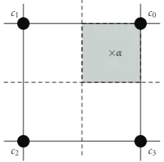
For the simplicity of the explanation, we do not consider Gray bit-mapping and neglect the edge effects, assuming that the point α falls in a region where it has four neighbor-ing signal points, as shown in Figure 2. The basic idea of the fast search method is to identify these four constellation points efficiently by exploiting the geometrical properties of the QAM constellation. The first step is to express the value ofαin the coordinate system of the real and imaginary parts of the source symbols as
sRα=Re{α}+ √
B−1
2 , s
I
α=Im{α}+ √
B−1 2 . (21) Then, the source symbols corresponding to the four neigh-boring constellation points can be identified easily by round-ing the values of sR
α and sIα up or down. For example, in Figure 2, the source symbolc0 = (cR0,cI0) corresponding to the upper right signal point can be obtained as cR
0 = sRα andcI0 = sIα. After determining the 4 source symbolsci = (ciR,cIi),i=0, 1, 2, 3, that correspond to the 4 nearest neigh-bors of α, we need to determine the order in which they
c1
c2 c3
c0
×α
Figure2: The fast QAM-search algorithm.
should be put on the list. The space between the neighbor-ing QAM constellation points is divided into 4 quadrants, as shown by the dashed lines inFigure 2, and the fractional parts ofsR
α andsIαare calculated to determine which quad-rant the valuesαfalls in by comparing the fractional parts to 0.5. Once the index of the quadrant is known, the source symbol corresponding to the signal point closest toα(c0in Figure 2) can be easily determined. The signal point furthest away fromα(c2inFigure 2) can also be identified. Based on this approach, the order between the other two source sym-bols (c1andc3inFigure 2) cannot be decided, but our simu-lations have shown that the actual order of the symbols is not important as long as the source symbol corresponding to the closest signal point is the first on the list, so we set arbitrary (e.g., random) order for those two signal points.
Finally, for each of the 4 source symbols, the algorithm calculates the corresponding channel symbol and checks whether the partial constraint is satisfied. If so, the sym-bol and the corresponding metric value are put on the lists. The remainingB−4 source symbols are ignored. Note that the symbols on the list will not be perfectly ordered some of the time. However, the algorithm ensures that the source symbol corresponding to the closest constellation point toα
will always be the first. As can be seen, the algorithm avoids the enumeration of all channel symbols satisfying the partial constraint and avoids the sorting operation altogether.
The edge effects are handled by projecting the values of
sR
α andsIαonto the boundaries of the constellation if neces-sary. That is, ifsR
α is smaller than 0, it is set to 0, and if it is greater than√B−1, it is set to√B−1. The imaginary partsI
α is transformed similarly. With this transformation, the trans-formedαpoint will fall on the boundary of a region with four neighboring constellation points, so the previously described algorithm can work properly. Since the original signal point
αwas outside the constellation, this perpendicular projection will not affect the identity of the closest constellation point.
5.2.2. PSK
In case ofB-ary PSK, the modulated complex channel sym-bol is determined by
Table3: Number of real operations for the preprocessing stages.
Implementation Number of Number of Number of Number of Total number additions multiplications divisions square roots of FLOPS
Complex 128.00 154.00 12.00 2.00 296.00
Real 158.00 196.00 18.00 4.00 376.00
Preprocessing stage of [12] 646.00 916.00 27.96 4.00 1593.96
In (22),Ris the radius of the constellation (usually unity), andΦis the rotation angle of the constellation (usually zero). The idea is similar to the square QAM case: we identify the source symbols corresponding to the two closest signal points toαwithout enumerating all signal points that satisfy the partial constraint. As the first step, we expressαin the coordinate system of the source symbols, which is an angular coordinate system:
sα= B 2π
Φα−Φ
, (23)
where Φα is the angle ofα, given by Φα = arctan(Im{α}, Re{α}), and arctan(·,·) is the four-quadrant arcus tangent function. Now we can easily determine the two source sym-bolsc0andc1 corresponding to the nearest neighbors ofsα by rounding up and down its value. For easy explanation, the edge effect will not be considered, soc0andc1are assumed to be in the set{0, 1,. . .,B−1}. If they fall outside, we can eas-ily map them back by adding or subtractingBto/from their values. Then, the fractional part ofsαis calculated to deter-mine which neighbor is the closest by comparing it to 0.5. The source symbol corresponding to the closest signal point is put on the list first, and the other source symbol will be the second, provided that they satisfy the partial constraint. The rest of the source symbols are ignored.
6. SIMULATION RESULTS
To illustrate the performance of the proposed sphere de-coding algorithm, we provide some simulation results. The simulated communication system had 2 transmit antennas (K=2), 2 receive antennas (L=2), and the 2×2 orthogo-nal design (6) was used as the SF code (M=KL=4,N=2,
G = 2). The OFDM modulation hadS = 128 subcarriers with an OFDM symbol period ofT=128μs. The frequency-selective MIMO channel was modeled by the COST 207 Typ-ical Urban 6-ray power delay profile [23].
Since the computational complexity of the preprocessing stage is independent of the applied modulation method and the sphere radius, it is discussed separately from the search-ing stage.Table 3shows the number of real operations exe-cuted by the complex and real preprocessing stages for each decoded code block. The entries in the first two rows of the table were obtained by substitutingM =4 andN =2 into the formulas of Tables1and2. The last row of the table con-tains the operation counts for the preprocessing stage of the sphere decoding algorithm in [12], which uses real QR de-composition. The QR decomposition was implemented ac-cording to the description in [20], and the values were ob-tained via simulations. The operation count values show that
10 12 14 16 18 20 22
10−5 10−4 10−3 10−2 10−1 100
Average SNR per bit (dB)
A
ver
age
b
it
er
ro
r
rat
e
2TX/2RX antennas, 64 QAM, 6-ray COST TU channel model
r=10
r=3
r=2
r=1.5
r=1
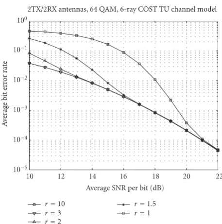
Figure3: Average bit error rate of the decoding algorithm with 64 QAM.
considerable complexity reduction can be achieved by im-plementing the preprocessing stage in the complex domain, even for smallMandNvalues. Particularly the number of necessary multiplications and square root operations can be reduced significantly. The computationally most expensive part was the calculation of the matrixHHH(orHTH), and the complexity of the Cholesky decomposition was negligi-ble due to the small size (2×2) of the matrix to be de-composed. It can also be observed that the preprocessing stage of [12] has considerably higher computational com-plexity, mainly due to the complexity of the QR decompo-sition.
We compared the complexity of the searching stages of different decoding algorithms by counting the number of real operations and averaging them over a large number (105−106) of experiments. The complex operations were counted according to the method described earlier. More-over, one floating-point comparison was counted as one addition. Some algorithms also used transcendent function evaluations, such as arcus tangent and arcus cosine; these op-erations are counted separately. The floating-point operation (FLOP) count includes all operations.
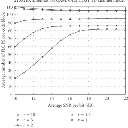
and the average FLOP counts per code block of the searching stage of the proposed algorithm is shown inFigure 4, both as a function of the average signal to noise ratio (SNR) in case of different radius values. The figure shows how the per-formance improves at the price of increased computational complexity. If the radius is small and the SNR is low, no solu-tion vector will fall inside the sphere some of the time, which reduces the average decoding complexity, but results in con-siderable performance degradation. It can also be observed that increasing the radius beyondr =3 has almost no effect on the decoding complexity of the searching stage. Therefore, the radius was set to a large enough value,r =10, to ensure ML performance in the SNR range of interest in case of all simulations.
6.1. 64 QAM
In case of 64 QAM modulation, we compared the complexity of the searching stages of five different decoding algorithms: the ML decoding algorithm (performing exhaustive search), the real-domain sphere decoding algorithm described in [10] (preprocessing stage: real Cholesky decomposition), the real-domain sphere decoding algorithm described in [12] (preprocessing stage: real QR decomposition), and the pro-posed decoding framework (preprocessing stage: complex Cholesky decomposition) with two symbol list generating method: the modulation-independent search and the fast QAM-specific search. Figure 5 depicts the BER curves as functions of the average SNR. It can be observed that all sphere decoding algorithms have the same performance as the ML decoding algorithm in the SNR range of interest. Table 4provides a detailed break-down of the number of op-erations for the searching stages, including the average value of nc. Since the variations of the operation counts is very small over the different SNR values, we only present the op-eration counts averaged over the simulated SNR values. In Figure 6, we also provide an example histogram ofnc, which is the number of valid signal vectors found in the sphere, at SNR of 16 dB.
Based on the above results, we can make several observa-tions. First, using sphere decoding, the computational com-plexity of the SF decoder can be reduced by orders of magni-tude without perceptible performance loss in the meaning-ful BER range. Second, the computational cost of the QAM-specific sphere decoding algorithms is dominated by the pre-processing stage. This is due to the combined effects of sphere radius reduction, the greedy tree search, and the fast symbol list generation method. Third, the complexity of the search-ing stages do not change considerably as the SNR increases, contradictory to the results of [13]. The reason is that in [13], the initial radius was reduced as the SNR increased (while we kept it constant), and the greedy tree search was not imple-mented. Fourth,nc takes the value of 1 with overwhelming relative frequency, and its average value is very close to 1, indicating that the first solution found by the greedy search was actually the ML solution most of the time. Finally, the searching stage of the algorithm described in [12] requires the least number of FLOPs, followed by the proposed fast
10 12 14 16 18 20 22
0 10 20 30 40 50 60 70 80 90 100 110
Average SNR per bit (dB)
A
ver
age
n
umber
o
f
F
L
O
PS
p
er
code
b
lock
2TX/2RX antennas, 64 QAM, 6-ray COST TU channel model
r=10
r=3
r=2
r=1.5
r=1
Figure4: Average FLOP counts of the searching stage of the decod-ing algorithms with 64 QAM.
10 12 14 16 18 20 22
10−5 10−4 10−3 10−2 10−1
Average SNR per bit (dB)
A
ver
age
b
it
er
ro
r
rat
e
2TX/2RX antennas, 64 QAM, 6-ray COST TU channel model
Algorithm of [10] Algorithm of [12]
Proposed algorithm, modulation independent Proposed algorithm, QAM-specific fast search ML decoding
Figure5: Average bit error rate of the decoding algorithms with 64 QAM.
Table4: The average umber of real operations for the searching stages, 64 QAM.
Algorithm Number of Number of Number of Number of Number of nc
additions multiplications divisions square roots FLOPS
ML decoding 167936 163840 0 0 331776 4096
Searching stage of [10] 183.6 48.5 8.1 8.1 248.3 1.00 Searching stage of [12] 57.8 20.8 4.1 0 82.7 1.00 Proposed method, modulation-indep. 1707.6 273.1 4.1 0 1984.8 1.00 Proposed method, fast search 76.1 26.3 4.0 0 106.4 1.00
0 0.5 1 1.5 2 2.5 3 3.5 4 10−6
10−5 10−4 10−3 10−2 10−1 100
ncthe number of vectors found in the sphere
R
elati
ve
fr
equency
(log)
Histogram ofnc: 2TX/2RX, 64 QAM, 6-ray COST TU channel model
Algorithm of [10] Algorithm of [12]
Proposed algorithm, modulation independent Proposed algorithm, QAM-specific fast search
Figure6: The histogram ofncfor the decoding algorithms with 64
QAM at SNR=16 dB.
depicted inFigure 7. Combining the FLOP counts of Tables 3and4, we observe that the total number of FLOPs per code block was reduced to about 64% of the FLOP count of the al-gorithm in [10] and to about 25% of the FLOP count of the algorithm in [12].
6.2. 16 PSK-QAM
The last experiment was conducted with 16 PSK-QAM mod-ulation. The constellation corresponding to this modulation method is shown inFigure 8. The 16 PSK-QAM constella-tion is made up of two PSK constellaconstella-tions. In case of nat-ural bit mapping, the inner PSK signal points can be gen-erated by (22) withR = 1,Φ = 0, andB = 8. The outer constellation points are determined by the same equation withR = cos(π/8) +√3 sin(π/8) = 1.5867, Φ = π/8, and
B=8.
The searching stages of four different decoding ap-proaches were compared: the ML decoding algorithm, the
10 12 14 16 18 20 22
0 500 1000 1500 2000 2500
Average SNR per bit (dB)
A
ver
age
n
umber
o
f
F
L
O
PS
p
er
code
b
lock
2TX/2RX antennas, 64 QAM, 6-ray COST TU channel model
Algorithm of [10] Algorithm of [12]
Proposed algorithm, modulation independent Proposed algorithm, QAM-specific fast search
Figure7: Average FLOP counts of the decoding algorithms with 64 QAM.
5
7 4
12 14
13 15
0 6
3
2 1 8
10
11 9
Figure8: The bit mapping for the 16 PSK-QAM constellation.
0 10 12 14 16 18 20 10−5
10−4 10−3 10−2 10−1
Average SNR per bit (dB)
A
ver
age
b
it
er
ro
r
rat
e
2TX/2RX antennas, 16 PSK-QAM, 6-ray COST TU channel model
Algorithm of [14]
Proposed algorithm, modulation independent Proposed algorithm, PSK-specific fast search ML decoding
Figure9: Bit error rate of the decoding algorithms with 16 PSK-QAM.
Table5: The average number of real operations for the searching stages, 16 PSK-QAM.
Algorithm Number of Number of Number of Number of Number of Number of nc
additions multiplications divisions square roots transc. op. FLOPS
ML decoding 10496 10240 0 0 0 20736 256
Searching stage of [14] 310.8 86.3 8.1 2.0 2.1 409.3 1.00 Proposed method, modulation-indep. 326.0 75.0 4.0 0 0 405.0 1.00 Proposed method, fast search 73.9 30.2 8.0 0 2.0 114.1 1.00
algorithms, the same complex Cholesky decomposition-based preprocessing stage was used, and the PSK-specific de-coding methods were modified for the 16 PSK-QAM modu-lation.
The average bit error rate curves of the above mentioned decoding methods are depicted inFigure 9. It is apparent that all sphere decoding approaches perform as well as the ML decoding algorithm. The detailed operation counts averaged over the simulated SNR range are given inTable 5. The aver-age number of transcendent function evaluations was added to the table, as some of the decoding algorithms calculate ar-cus tangent and arar-cus cosine values. The histogram of the
nc values at SNR=14 dB can be observed inFigure 10. Fi-nally, for overall comparison, the total number of FLOPS per code block, including both the preprocessing and the search-ing stages, is shown inFigure 11.
There are two important observations to be made. First, the constellation-independent search performs slightly bet-ter than the search method in [14]. However, for larger con-stellation sizes, built from PSK concon-stellations, the method of [14] is expected to have lower computational complexity than the modulation-independent decoding algorithm. Sec-ond, the proposed fast nearest-neighbor search algorithm
achieved significant complexity reduction compared to the search stage of [14]. Taking into account both decoding stages, the total number of FLOPs was reduced by the pro-posed decoding algorithm to about 58% of the FLOPs of the decoding method described in [14].
7. CONCLUSION
0 0.5 1 1.5 2 2.5 3 3.5 4 10−8
10−7 10−6 10−5 10−4 10−3 10−2 10−1 100
ncthe number of vectors found in the sphere
A
ver
age
fr
equency
(lo
g)
Histogram ofnc: 2TX/2RX, 16 PSK-QAM, 6-ray COST TU channel model
Algorithm of [14]
Proposed algorithm, modulation independent Proposed algorithm, PSK-specific fast search
Figure10: The histogram ofncfor the decoding algorithms with 16
PSK-QAM at SNR=14 dB.
8 10 12 14 16 18 20
0 100 200 300 400 500 600 700 800
Average SNR per bit (dB)
A
ver
age
n
umber
o
f
F
L
O
PS
p
er
code
b
lock
2TX/2RX antennas, 16 PSK-QAM, 6-ray COST TU channel model
Algorithm of [14]
Proposed algorithm, modulation independent Proposed algorithm, PSK-specific fast search
Figure11: Average FLOP counts of the decoding algorithms with 16 PSK-QAM.
the algorithm described in [12] seems to be the right choice, but in case of broadband MIMO-OFDM systems, where the preprocessing stage has to be executed for every code block, our algorithm offers the lowest decoding complexity without any perceptible performance loss.
Note
The work described in this manuscript was in part presented at the European Wireless Conference in February 2004 [24] and at the IEEE International Conference on Communica-tions in January 2004 [25].
REFERENCES
[1] D. Agrawal, V. Tarokh, A. Naguib, and N. Seshadri, “Space-time coded OFDM for high data-rate wireless communication over wideband channels,” inProceedings of 48th IEEE Vehic-ular Technology Conference (VTC ’98), vol. 3, pp. 2232–2236, Ottawa, Ontario, Canada, May 1998.
[2] H. B¨olcskei and A. J. Paulraj, “Space-frequency coded broad-band OFDM systems,” inProceedings of IEEE Wireless Commu-nications and Networking Conference (WCNC ’00), vol. 1, pp. 1–6, Chicago, Ill, USA, September 2000.
[3] Y. Gong and K. B. Letaief, “An efficient space-frequency coded wideband OFDM system for wireless communications,” in
Proceedings of IEEE International Conference on Communica-tions (ICC ’02), vol. 1, pp. 475–479, New York, NY, USA, April–May 2002.
[4] Z. Hong and B. L. Hughes, “Robust space-time codes for broadband OFDM systems,” in Proceedings of IEEE Wire-less Communications and Networking Conference (WCNC ’02), vol. 1, pp. 105–108, Orlando, Fla, USA, March 2002.
[5] Z. Liu, Y. Xin, and G. B. Giannakis, “Space-time-frequency coded OFDM over frequency-selective fading channels,”IEEE Transactions on Signal Processing, vol. 50, no. 10, pp. 2465– 2476, 2002.
[6] W. Su, Z. Safar, M. Olfat, and K. J. R. Liu, “Obtaining full-diversity space-frequency codes from space-time codes via mapping,” IEEE Transactions on Signal Processing, vol. 51, no. 11, pp. 2905–2916, 2003.
[7] S. M. Alamouti, “A simple transmit diversity technique for wireless communications,”IEEE Journal on Selected Areas in Communications, vol. 16, no. 8, pp. 1451–1458, 1998. [8] V. Tarokh, H. Jafarkhani, and A. R. Calderbank, “Space-time
block codes from orthogonal designs,”IEEE Transactions on Information Theory, vol. 45, no. 5, pp. 1456–1467, 1999. [9] E. Viterbo and J. Bouros, “A universal lattice code decoder
for fading channels,”IEEE Transactions on Information Theory, vol. 45, no. 5, pp. 1639–1642, 1999.
[10] A. M. Chan and I. Lee, “A new reduced-complexity sphere de-coder for multiple antenna systems,” inProceedings of IEEE In-ternational Conference on Communications (ICC ’02), vol. 1, pp. 460–464, New York, NY, USA, April–May 2002.
[11] E. Agrell, T. Eriksson, A. Vardy, and K. Zeger, “Closest point search in lattices,”IEEE Transactions on Information Theory, vol. 48, no. 8, pp. 2201–2214, 2002.
[12] M. O. Damen, H. El Gamal, and G. Caire, “On maximum-likelihood detection and the search for the closest lattice point,” IEEE Transactions on Information Theory, vol. 49, no. 10, pp. 2389–2402, 2003.
[13] H. Vikalo and B. Hassibi, “Maximum likelihood sequence de-tection of multiple antenna systems over dispersive channels via sphere decoding,”EURASIP Journal on Applied Signal Pro-cessing, vol. 2002, no. 5, pp. 525–531, 2002.
[15] K.-W. Wong, C.-Y. Tsui, R. S.-K. Cheng, and W.-H. Mow, “A VLSI architecture of a K-best lattice decoding algorithm for MIMO channels,” inProceedings of IEEE International Sympo-sium on Circuits and Systems (ISCAS ’02), vol. 3, pp. 273–276, Scottsdale, Ariz, USA, May 2002.
[16] B. Widdup, G. Woodward, and G. Knagge, “A highly-parallel VLSI architecture for a list sphere detector,” inProceedings of IEEE International Conference on Communications (ICC ’04), vol. 5, pp. 2720–2725, Paris, France, June 2004.
[17] A. Burg, M. Wenk, M. Zellweger, M. Wegmueller, N. Felber, and W. Fichtner, “VLSI implementation of the sphere decod-ing algorithm,” in Proceedings of 30th European Solid-State Circuits Conference (ESSCIRC ’04), pp. 303–306, Leuven, Bel-gium, September 2004.
[18] A. Burg, M. Borgmann, C. Simon, M. Wenk, M. Zellweger, and W. Fichtner, “Performance tradeoffs in the VLSI imple-mentation of the sphere decoding algorithm,” inProceedings of 5th IEE International Conference on 3G Mobile Communica-tion Technologies (IEE 3G ’04), pp. 92–96, London, UK, Octo-ber 2004.
[19] W. Su and X.-G. Xia, “Signal constellations for quasi-orthogonal space-time block codes with full diversity,”IEEE Transactions on Information Theory, vol. 50, no. 10, pp. 2331– 2347, 2004.
[20] G. H. Golub and C. F. Van Loan,Matrix Computations, Johns Hopkins University Press, Baltimore, Md, USA, 1996. [21] U. Fincke and M. Pohst, “Improved methods for calculating
vectors of short length in a lattice, including a complexity anal-ysis,”Mathematics of Computation, vol. 44, no. 170, pp. 463– 471, 1985.
[22] B. Hassibi and H. Vikalo, “On the expected complexity of in-teger least-squares problems,” inProceedings of IEEE Interna-tional Conference on Acoustics, Speech, and Signal Processing (ICASSP ’02), vol. 2, pp. 1497–1500, Orlando, Fla, USA, May 2002.
[23] G. L. St¨uber,Principles of Mobile Communication, Kluwer Aca-demic, Boston, Mass, USA, 2001.
[24] Z. Safar, W. Su, and K. J. R. Liu, “Fast sphere decoding of space-frequency block codes via nearest neighbor signal point search,” inProceedings of 5th European Wireless Conference, Mobile and Wireless Systems beyond 3G (EW ’04), Barcelona, Spain, February 2004.
[25] Z. Safar, W. Su, and K. J. R. Liu, “A fast sphere decoding frame-work for space-frequency block codes,” inProceedings of IEEE International Conference on Communications (ICC ’04), vol. 5, pp. 2591–2595, Paris, France, June 2004.
Zoltan Safarreceived the University Diplo-ma in electrical engineering from the Tech-nical University of Budapest, Budapest, Hungary, in 1996, and the M.S. and Ph.D. degrees in electrical and computer engi-neering from the University of Maryland, College Park, Maryland, USA, in 2001 and 2003, respectively. From September 2003 to March 2005, he was an Assistant Professor at the Department of Innovation, IT
Uni-versity of Copenhagen, Copenhagen, Denmark. Currently, he is a Senior Design Engineer at Modem System Design, Nokia, in Copenhagen, Denmark. His research interests include wireless communications and multimedia signal processing, with particular
focus on multiple-input multiple-output (MIMO) wireless com-munication systems and space-time and space-frequency coding. Dr. Safar received the Outstanding Systems Engineering Graduate Student Award from the Institute for Systems Research, University of Maryland, in 2003, and the Invention of the Year Award (to-gether with W. Su and K. J. R. Liu) from the University of Maryland in 2005.
Weifeng Su received the Ph.D. degree in electrical engineering from the University of Delaware, Newark, in 2002. He received his B.S. and Ph.D. degrees in mathemat-ics from Nankai University, Tianjin, China, in 1994 and 1999, respectively. His research interests span a broad range of areas from signal processing to wireless communica-tions and networking, including space-time coding and modulation for MIMO wireless
communications, MIMO-OFDM systems, cooperative communi-cations for wireless networks, and ultra-wideband (UWB) commu-nications. He has published more than 20 journal papers and 30 conference papers in the related areas. Dr. Su is an Assistant Pro-fessor in the Department of Electrical Engineering, the State Uni-versity of New York (SUNY) at Buffalo. From June 2002 to March 2005, he was a Postdoctoral Research Associate with the Depart-ment of Electrical and Computer Engineering and the Institute for Systems Research (ISR), University of Maryland, College Park. Dr. Su received the Signal Processing and Communications Faculty Award from the University of Delaware in 2002 as an outstanding graduate student in the field of signal processing and communica-tions. In 2005, he received the Invention of the Year Award from the University of Maryland. He won the first prize of the Chinese Olympic Mathematics Competition in 1990.
K. J. Ray Liureceived the B.S. degree from the National Taiwan University in 1983, and the Ph.D. degree from UCLA in 1990, both in electrical engineering. He is a Profes-sor and Director of Communications and Signal Processing Laboratories of Electri-cal and Computer Engineering Department and Institute for Systems Research, Univer-sity of Maryland, College Park. His research contributions encompass broad aspects of