Bandwidth Enhanced Circular and Annular Ring Sectoral
Patch Antennas
Uma Balaji*
Abstract—This paper presents the enhancement of bandwidth in circular and annular ring sectoral patch antennas. The cavity model approach has been used in identifying the higher order mode resonances that are close to each other in the sectoral patches. Bandwidth enhancement centered around these higher order mode resonances is achieved through the use of either a shorting pin or a parasitic patch. The sectoral patches have been simulated using ANSYS HFSS. The optimum position of the shorting pin and the dimension and position of the parasitic patch were determined through parametric simulations on HFSS. Measurements showed that the annular ring sectoral patch with optimally positioned shorting pin achieved 6.3 percent bandwidth with a return loss performance greater than 10 dB while the circular sector patch with a parasitic patch achieved 5.6 percent.
1. INTRODUCTION
Microstrip patch antennas have been popular for their size, light weight, and ease of production. The commonly used configuration is a rectangular patch whose geometry enables easy positioning as an element of a planar array. The rectangular, circular and ring patch antennas are easy to analyze and design using transmission line model or cavity model [1]. The cavity model based solutions are in close agreement with the full wave electromagnetic analyses such as moment method and finite element method. While rectangular patches are popular for their geometry, circular and annular ring patches offer additional capabilities such as enabling ease of dual frequency operation and circular polarization support. However, all of these patches are able to operate over a narrow bandwidth of two percent centered at the resonant frequency.
Bandwidth enhancement of rectangular patches by including parasitic patches has been reported extensively [2, 3]. Stacked geometries of circular and annular ring patches have been studied for bandwidth enhancement. The cavity model was extended for the design and analysis of circular, stacked circular and annular ring patches [4–7]. Shorting pins at selected positions in the geometry of patches have been used for its frequency tuning ability [8–10] of one or more higher order resonances.
Circular and ring sectoral patches offer multiple higher order resonances close to each other similar to full patches while being smaller in size. This capability of multiple resonances have been shown to be used for dual band applications [11–14]. Sectoral patch with square notches has been reported for circular polarization application [15]. Gap-coupled parasitic sectoral patch for bandwidth enhancement has been reported in a study [16]. The configuration of a coaxial probe fed sector placed at a radial distance from three other gap coupled parasitic sectors in a three quarter circular layout provided increased bandwidth while increasing the size of the antenna [16]. Microstrip line fed circular sector array placed in a circular layout with four or more elements as presented in [17] was shown to increase gain of the antenna.
Received 5 March 2019, Accepted 12 May 2019, Scheduled 22 May 2019
* Corresponding author: Uma Balaji ([email protected]).
This paper presents a unique approach to increase the bandwidth of sectoral patches while keeping the size of the antenna small in comparison to those presented in [11–16]. The enhanced bandwidth has been achieved through a careful choice of the higher order mode resonances in the patch and the use of either a shorting pin or a parasitic patch. The sectoral patches that are a 90◦ sector (a quarter of the full patch) have been simulated with ANSYS HFSS for return loss and radiation pattern. In particular, a parametric analysis was performed to determine the optimum position of shorting pin and size of the parasitic element. The bandwidth of interest in the parametric analysis was centered around the higher order resonant modes that are close to each other. The resonant frequencies of the sectoral patches have been determined using cavity model prior to simulation. The optimum position of the microstrip feed was determined through the parametric analysis. The patches were fabricated on FR4 substrate of height 1.59 mm, relative permittivity of 4.1 and loss tangent of 0.02. The technique used in bandwidth enhancement has been validated through measurements.
2. THEORY
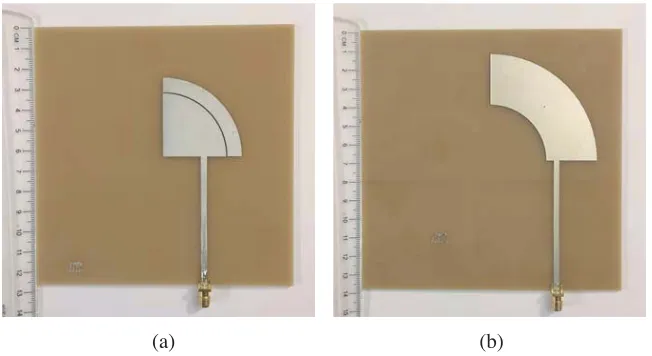
The prototype of the patch antennas that have been investigated in this work are shown in Figure 1. They are — (a) circular sectoral patch with a parasitic annular ring at the loop edge and excited by a microstrip feed, (b) an annular ring sectoral patch (90◦) that is excited by a microstrip feed and has one shorting pin in the patch.
(a) (b)
Figure 1. Patch antennas prototype, (a) circular sectoral patch (radius = 30.8) with a parasitic annular ring of inner radius = 31.8 mm and outer radius = 38.8 mm, (b) annular ring sectoral patch (inner radius = 30 mm, outer radius = 57 mm) with a shorting pin of diameter 1 mm located at 45◦ and radius of 41 mm.
2.1. Circular Sectoral Patch
The cavity model approach as described in [1] yields the field distribution in cylindrical coordinate system inside the one quarter circular sectoral patch (Figure 1(a)) and the resonant frequency of the antenna. SeveralT Mmn0 modes are excited in the quarter cylindrical cavity formed by the electric walls
on the top surface of the circular sectoral patch, the bottom surface (ground plane) of the patch and the magnetic walls on the three surfaces formed between the top surface and ground plane. A number of resonant modes with even values for m starting from 2 and nstarting from 1 can be excited in the cavity at different frequencies. The value ofmcorresponds to the azimuthal variation andncorresponds to the radial variation of the fields in the cavity. The subscript zero in the T Mmn0 indicates no field
variation in the height of the patch. The resonant frequency, fr for variousT Mmn0 modes is given as
fr = 2π√1μχ
mn
where ae is the effective radius of the patch, and χmn represents the nth zero of the derivative of the Bessel function of mth order, Jm(x), with μ and being the permeability and permittivity of the substrate of the patch. The effective radius is obtained by incorporating the fringing of the fields at the loop edge of the patch. If the patch radius isa and substrate height ish, the effective radius ae as described in [1] has been used for that sectoral patch and is given as
ae=a
1 + 2h
πar
lnπa
2h + 1.7726
(2)
The higher order modes that have values of resonant frequencies very close to each other are T M420, T M810,T M220. The resonant frequencies for these modes are obtained from the values ofχ42= 9.2824, χ81= 9.6474 andχ22= 9.9694. The resonant frequencies corresponding to these modes are 6.8873 GHz,
7.1581 GHz, and 7.3970 GHz for the radius of the patch equal to 30.8 mm on FR4 substrate. The enhancement of bandwidth is centered about these resonant frequencies in the design of the patch of Figure 1(a) with a parasitic ring placed at the loop edge of circular sectoral patch. A parametric analysis on HFSS was used to determine the spacing and the width of the parasitic ring for optimum bandwidth centered on the identified resonant frequencies of the circular sectoral patch.
2.2. Annular Ring Sectoral Patch
The one quarter annular ring patch (Figure 1(b)) is analyzed using the cavity model to determine the frequency of resonant modes. The top surface and bottom surface (ground plane) are the electric wall of a cylindrical cavity while the inner and outer cylindrical surfaces at the radial edges of the annular ring form magnetic walls. These boundary conditions are the same as that of a full annular ring. The surface at the 0◦ and 90◦ edges of the one quarter annular ring are magnetic walls while they can be a magnetic or electric wall for a full annular ring due to rotational symmetry. Hence the resonant frequencies of a one quarter annular ring are a subset of full annular ring. The characteristic equation for determining the resonant modes in the cavity is obtained from these boundary conditions as derived in [9] for a full annular ring and is given as
dJm(kρae)
dρ
dYm(kρbe)
dρ −
dJm(kρbe)
dρ
dYm(kρae)
dρ = 0 (3)
In the characteristic equation,ae andbe correspond to the inner and outer effective radii of the annular ring patch; Jm and Ym are the Bessel functions of the first and second kinds of order m, wherem is an integer greater than 1 and represents the variation of the fields in the azimuthal direction. The roots of the characteristic equations yields the resonant frequencies of theT Mmn0 modes that are excited in the
ring resonators. m, which is the order of the Bessel function, represents the azimuthal variation of the field in the patch, and nis the number of the roots in the solution (for a value ofm) to characteristic equation and represents the radial variations of fields in the patch. For the 90◦(one quarter ring) sectoral patch, m can only take even values. The well known numerical method of bisection to determine the roots of an equation is used to determine the wave numberskρin the characteristic equation for various even values of m. The wave number kρ and the resonant frequency fr of the modes are related to dielectric constant r of the substrate by
kρ= 2πfr
(μor) (4)
Due to fringing of the fields at the edges of the patch, the patch appears slightly bigger at the outer edge and smaller at the inner edge. The effective radius of the patchae and be as related to the actual radiusaand b as given in [9] and has been used in this work. They are given as
ae = a
1− 2h
πarΔCa (5)
be = b
1 + 2h
πbrΔCb (6)
ΔCa = ln2ah + 1.41r+ 1.7726 + ha(0.286r+ 1.65) (7)
ΔCb = ln b
2h + 1.41r+ 1.7726 + h
The characteristic equation for the determination of the resonant frequency of the sectoral patch is the same as that of full annular ring patch except that m takes on only even values due to the boundary condition at the straight edges of the sectoral patch. Also, the open straight edges at 0◦ and 90◦ of the sectoral patch cavity support a magnetic wall boundary condition and radiate. The frequencies of resonance of the T M620 and T M820 modes of the sectoral annular ring patch with inner radius of
30 mm and outer radius of 57 mm were determined from the characteristic equation as 6.27 GHz and 6.65 GHz respectively. A microstrip feed was used to excite the sectoral ring patch of this dimension at the straight edge (Figure 1(b)). The frequency band of interest was centered around these two resonant modes. A shorting pin inserted at 45◦ for this sectoral ring patch was investigated. A parametric analysis on HFSS was performed to identify the position of the shorting pin and the location of the microstrip feed for a return loss performance better than 10 dB in the frequency band of interest.
3. RESULTS
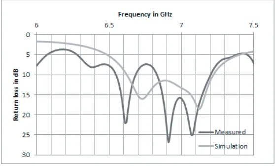
The width of the parasitic ring sector and the space between the fed patch and parasitic ring patch were determined from HFSS parametric analysis for the circular sectoral patch in Figure 1(a). A spacing of 1 mm between the parasitic element and the fed sectoral circular patch was found to provide a return loss greater than 10 dB in the band. The optimum width of the parasitic element was found to be 7 mm. The microstrip feed position was included in the parametric analysis, and its location was determined to be 18.5 mm from the origin. The patch was fabricated with these optimum dimensions. The measured and simulated return losses for this patch are shown in Figure 2. A return loss of better than 10 dB is achieved over a 8 percent bandwidth through simulation. However, measurements indicate bandwidth achieved to be 5.6 percent. The measurements also indicate that a bandwidth of 10.2 percent is achieved for a return loss of better than 7.4 dB. While optimizing the circular sector patch with the parasitic element, the simulation indicated that for a small portion of the optimized band, the return loss is close to 10 dB. Due to fabrication tolerances, one of the three identified resonances that are close to each other separated from the band causing the achieved bandwidth to be lower. A plot of the simulated radiation pattern of the patch at three different frequencies in the band is shown in Figure 3. The radiation characteristics at various frequencies in the antenna bandwidth are similar.
A 90◦ annular ring sectoral antenna (Figure 1(b)) on an FR4 substrate was analyzed around the center frequency of 6.5 GHz. The microstrip feed position as well as the location of shorting pin (diameter 1 mm) placed at 45◦ of the quarter ring was determined from the parametric analysis. The shorting pin placed at 41 mm and feed position at 34 mm radius yielded a return loss better than 10 dB in the band centered at 6.5 GHz. The measurement, as shown in Figure 4, is in agreement with the simulation. A 6.3 percent bandwidth indicated by simulation is obtained from the fabricated patch. The simulated
(a) (b)
Figure 3. Simulated radiation pattern of circular sectoral patch antenna with a parasitic ring, (a) yz
plane, (b)xz plane.
Figure 4. Measured and simulated return loss microstrip fed 90◦annular ring sector patch with shorting pin.
(a) (b)
Figure 5. Simulated radiation pattern of annular ring sectoral patch antenna, (a) yz plane, (b) xz
radiation patterns of the antenna in the xz and xy planes at three different frequencies close to band edges and center of the band is shown in Figure 5. The radiation is directional with an asymmetric pattern, but align closely in the frequency band.
4. CONCLUSION
This paper has presented methods to enhance the bandwidth of circular and annular ring sectoral patches and verified them with measurements. The resonant frequencies of sectoral patches have been determined using the cavity model. The modal resonances that are close to each other have been targeted for bandwidth enhancement by suitable use of shorting pins and parasitic elements. Parametric simulation on HFSS was successfully used to identify the location of shorting pins and the size and position of a parasitic element to obtain enhanced bandwidths in circular sectoral and annular ring sectoral patches. By using shorting pins, higher order modes have been tuned for better impedance match in the sectoral patches. Additionally, it has been shown that improvement of bandwidth in circular sectoral patch with a parasitic ring element is obtained without increasing the size of the antenna appreciably. The annular ring sectoral patch achieved 6.3 percent bandwidth with a return loss performance of 10 dB or better in the band with one shorting pin located optimally to support the modes. The circular sectoral patch with a parasitic element achieved a 5.6 percent bandwidth for a return loss performance of 10 dB or better.
REFERENCES
1. Balanis, C. A.,Antenna Theory Analysis and Design, 2nd edition, John Wiley and Sons Inc., 1997. 2. Wood, C., “Improved bandwidth of microstrip antennas using parasitic elements,”IEE Proceedings
H: Microwaves, Optics and Antennas, Vol. 127, No. 4, 231–234, 1980.
3. Ketineni, R. V., U. Balaji, and A. Das, “Improvement of bandwidth in microstrip antennas using parasitic patch,”IEEE Antennas and Propagation Symposium, 1943–1947, 1992.
4. Dahele, J. S., K. F. Lee, and D. P. Wong, “Dual-frequency stacked annular-ring microstrip antenna,” IEEE Transactions on Antennas and Propagation, Vol. 35, No. 11, 1281–1285, November 1987. 5. Gomez-Tagle, J. and C. G. Christodoulou, “Extended cavity model analysis of stacked microstrip
ring antennas,” IEEE Transactions on Antennas and Propagation, Vol. 45, No. 11, 1626–1635, November 1997.
6. Nurie, N. S. and R. J. Langley, “Input impedance of concentric ring microstrip antennas for dual frequency band operation including surface wave coupling,” IEE Proceedings H — Microwaves, Antennas and Propagation, Vol. 137, No. 6, 331–336, November 1990.
7. Chen, X., G. Fu, S. X. Gong, Y. L. Yan, and W. Zhao, “Circularly polarized stacked annular-ring microstrip antenna with integrated feeding network for UHF RFID readers,” IEEE Antennas and Wireless Propagation Letters, Vol. 9, 542–545, 2010.
8. Zhang X. and L. Zhu, “Patch antennas with loading of a pair of shorting pins toward flexible impedance matching and low cross polarization,”IEEE Transactions on Antennas and Propagation, Vol. 64, No. 4, 1226–1233, April 2016.
9. Balaji, U., “Circular patch antenna for radio LAN applications,” International Conference on Antennas and Propagation, 723–726, 2003.
10. Goto, J., S. Yamaguchi, K. Kihira, T. Toru, and H. Miyashita, “Dual frequency patch antenna using partially shorted annular ring patch antenna,” IEEE Antennas and Propagation Symposium URSI, 1869–1870, 2014.
11. Richards, W. F., J. D. Ou, and S. A. Long, “A theoretical and experimental investigation of annular, annular sector and circular sector microstrip antennas,”IEEE Transactions on Antennas and Propagation, Vol. 32, No. 8, 864–867, August 1984.
13. Deshmukh, A. A. and N. V. Phatak, “Broadband sectoral microstrip antenna,” IEEE Antennas and Wireless Propagation Letters, Vol. 14, 727–730, 2015.
14. Zhang, J., Y. Li, Z. Liang, S. Zheng, and Y. Long, “Design of a multifrequency one-quarter-rings microstrip antenna,”IEEE Antennas and Wireless Propagation Letters, Vol. 14, 209–212, 2015. 15. Tanaka, T., M. Takahashi, and K. Ito, “Study on the radiation characteristics of a miniaturized
circularly polarized circular sector patch antenna,” IEEE Antennas and Propagation Symposium, 1560–1564, 2006.
16. Kandwal, A. and S. K. Khah, “A novel design of gap-coupled sectoral patch antenna,” IEEE Antennas and Wireless Propagation Letters, Vol. 12, 674–677, 2013.