An Efficient Code Compression Technique for Embedded
Systems
Ms. Konduru Gowthami & Vadite Nanuku Naik
1 PG Student, Dept. Of VLSI and Embedded systems, SKR College Of Engineering & Technology, AP
2 Asst Professor, Dept. Of VLSI and Embedded systems, SKR College Of Engineering &Technology,AP.
ABSTRACT: Memory plays a crucial role in designing embedded systems. Embedded systems are constrained by theavailable memory. A larger memory can accommodate more and large applications but increases cost, area, as well as energy requirements. Code-compression techniques address this issue by reducing the code size of application programs. It is a major challenge to develop an efficient code-compression technique that can generate substantial reduction in code size without affecting the overall system performance. We
present an efficient code-compression
technique, which significantly improves the compression ratio. Two previously proposed algorithm are evaluated. The first algorithm is dictionary-based method, provides a small separated dictionary is proposed to restrict the codeword length of high-frequency instructions, and a novel dictionary selection algorithm is proposed to achieve more satisfactory instruction selection, which in turn may reduce the average CR. The second algorithm is mixed-bit saving dictionary selection (MBSDS) the fully separated dictionary architecture is proposed to improve the performance of the dictionary-based decompression engine. This architecture has a better chance to parallel decompress instructions than existing single dictionary decoders Additionally, this paper offers a third algorithm namely, to combine the two previously proposed schemes along with run length encoding to compress the code.
KEYWORDS:Bitmasks, code compression, decompression, embedded systems, memory, compression ratio, codedensity, run length encoding.
I.INTRODUCTION
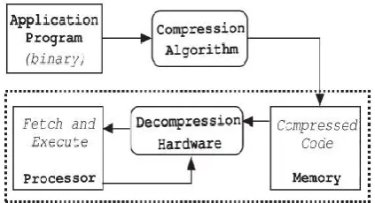
MEMORY is one of the key driving factors in embedded-system design because a larger memory indicates an increased chip area, more power dissipation, and higher cost. As a result, memory imposes constraints on the size of the application programs. Code-compression techniques address the problem by reducing the program size. Fig. 1 shows the traditional code-compression and decode-compression flow where the compression is done offline (prior to execution) and the compressed program is loaded into the memory. Compression ratio (CR), widely accepted as a primary metric for measuring the efficiency of code compression, is defined as
by considering mismatches. The basic idea is to create instruction matches by remembering a few bit positions. The efficiencies of these techniques are limited by the number of bit changes used during compression. It is obvious that if more bit changes are allowed, more matching sequences will be generated. However, the cost of storing the information for more bit positions offsets the advantage of generating more repeating instruction sequences. Studies [4] have shown that it is not profitable to consider more than three bit changes when 32-b vectors are used for compression. There are various complex compression algorithms that can generate major reduction in code size. However, such compression scheme requires a complex decompression mechanism and thereby reduces overall system performance. It is a major challenge to developan efficient code-compression technique that can generate Substantial code-size reduction without introducing any decompression penalty (and thereby reducing performance).
Fig. 1.Code-compression methodology. Various challenges in bitmask-based compression by developing efficient techniques for application-specific bitmask selection and bitmask-aware dictionary selection to further improve the CR[3]. In dictionary-based schemes, entire sequences of common instructions are selected and replaced by a
single new codeword which is then used as an index to a dictionary that contains the original sequence of instructions. In both cases, lookup tables (LUTs) are used to store the original instructions. The encoded instructions serve as indices to those tables. One of the major problems is that the tables can become large in size, thus diminishing the advantages that could be obtained by compressing the code.
II.RELATED WORK
The first code-compression technique for embedded processors was proposed by Wolfe and Chanin [5]. Their technique uses Huffman coding, and the compressed program is stored in the main memory. The decompression unit is placed between the main memory and the instruction cache. They used a Line Address Table (LAT) to map original code addresses to compressed block addresses. Lekatsas and Wolf [6] proposed a statistical method for code compression using arithmetic coding and Markov model. Lekatsaset al. [7] proposed a dictionary-based decompression prototype that is capable of decoding one instruction per cycle. The idea of using dictionary to store the frequently occurring instruction sequences has been explored by various researchers [9], [10]. Fig. 2 shows an example of the standard dictionary-based code compression.
compressed by using a dictionary-based scheme. Nam et al.
[12] also use dictionary-based scheme to compress fixed-format VLIW instructions. Various researchers have developed code-compression techniques for VLIW architectures with flexible instruction formats [13], [11]. Larin and Conte [10] applied Huffman coding for code compression. [11] usedTunstall coding to perform variable-to-fixed compression. Lin
et al. [12] proposed a Lempel–Ziv–Welch
(LZW)-based code compression for VLIW processors using a variable-sized-block method. Ros and Sutton [11] have used a post compilation register reassignment technique to generate compression-friendly code. Das et al.
[13] applied code compression on variable-length instruction-set processors.
3. CODE COMPRESSION USING
BITMASKS
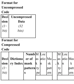
The motivation of our work is based on the analysis presented in Sec-tion 2. Our approach tries to incorporate maximum bit changes using mask patterns without adding signicant cost (extra bits) so that the compression ratio is improved. Our compression technique also en-sures that the decompression efciency remains the same compared to the existing techniques. Our scheme considers a 32-bit program code (vector) and uses mask patterns. Figure 2 shows the generic encoding scheme used by our compression technique. A compressed code can store information regarding multiple mask patterns. For each pattern, the generic encoding stores the mask type, (requires two bits to dis-tinguish between 1-bit, 2-bit, 4-bit, or 8-bit), the location where mask needs to be applied, and the mask pattern.
Format for Uncompressed
Code
Deci sion
Uncompressed
Data
(1− bit)
(32
bits)
Format for Compressed
Code
Deci sion
Dictiona ry Index
Numb er of
M as k
Loc atio n
Ma sk
.... .
M as k
Loc atio n
Mas k
mask pattern s
(1−
bit)
ty pe
patt ern
ty pe
patt ern
Extra bits for considering mismatches
Figure 2: Encoding Format for Our Compression Technique
The number of bits needed to indicate a location will depend on the mask type. A mask of size s can be applied on (32 s) number of places. For example, a 8-bit mask can be applied only on four places (byte boundaries). Similarly, a 4-bit mask can be applied on eight places (byte and half-byte boundaries). Consider a scenario where a 32-bit word is compressed using one 4-bit mask at second half-byte boundary, and one 8-bit mask at fourth byte boundary, the compressed code will appear as shown below.
0 1 0 1 0 01 0 4−bi t 1
1
1 1
8−bi
t Dictionar y Index mas k mas k
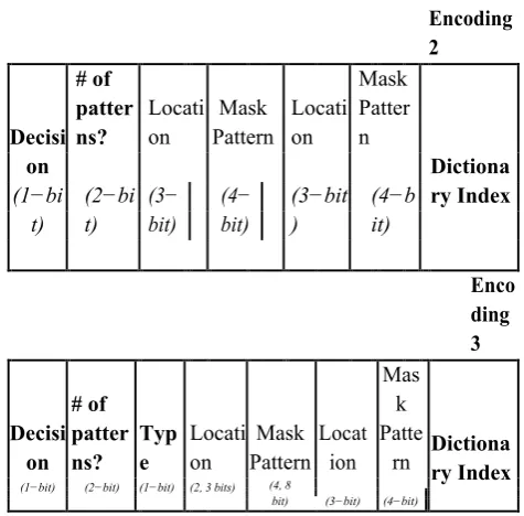
The generic encoding scheme can be further optimized. For code compression, we have found that using up to two bitmasks is sufcient to achieve a good compression ratio. We explored various customized version of our encoding format to gure out which encoding format works better across the target architectures. Clearly, a 32-bit mask pat-tern is not pro table. The 16-bit mask is also not useful unless there are too many mismatches which a 4-bit or 8-bit (or combined 12 bit) mask cannot capture. We explored all possible encoding scenarios us-ing 4-bit and 8-bit masks and observed that three customized encoding formats shown in Figure 3 work very well across applications and tar-get architectures. The rst encoding (Encoding 1) uses a 8-bit mask, the second encoding (Encoding 2) uses up to two 4-bit masks, and the third encoding (Encoding 3) uses up to two masks where rst mask can be either 4-bit or 8-bit whereas the second mask is always 4-bit.
Decisi on # of patter ns? Locati on Mask
Pattern Dictionary
Index Encoding 1
(1−bi t) (1−b it) (2− bit) (8−bit) Encoding 2 Decisi on # of patter ns? Locati on Mask Pattern Locati on Mask Patter n Dictiona ry Index (2−bi t) (3− bit) (4− bit) (3−bit ) (4−b it) (1−bi t) Enco ding 3 Decisi on # of patter ns? Typ e Locati on Mask Pattern Locat ion Mas k Patte
rn Dictionary Index
(1−bit) (2−bit) (1−bit) (2, 3 bits) (4, 8
bit) (3−bit) (4−bit)
Figure 3: Three Customized Encoding Formats
We rst explain our code compression algorithm. Next, we present our decompression mechanism. In Section 4, we report performance of these customized encoding formats.
3.1 Compression Algorithm
new repeating sequences they can create from mismatches using bitmasks with cost constraints. Table 1 provides the cost for the choices. For example, it is costly to use two 4-bit masks (cost: 15 4-bits) if an 8-4-bit mask (cost: 10 bits) can create the match. The second step chooses the smallest possible dictionary size without signicantly affecting the compression ratio. It is useful to consider larger dictionary sizes when the current dictionary size can-not accommodate all the vectors with frequency value above certain threshold. However, there are certain disadvantages of increasing the dictionary size. The cost of using a larger dictionary is more since the dictionary index becomes bigger. The cost increase is balanced only if most of the dictionary is full with high frequency vectors. Most impor-tantly, a bigger dictionary increases the access time and thereby reduces decompression efciency.
Algorithm 1:Code Compression using Mask Patterns
Input: Original code (binary) divided into 32-bit vectors Outputs: Compressed code and dictionary Begin
Step 1: Create the frequency distribution of the vectors. Step 2: Create the dictionary based on Step 1.
Step 3: Compress each 32-bit vector using cost constraints. Step 4: Handle and adjust branch targets.
returnCompressed code and dictionaryEnd
The third step converts each 32-bit vector into
compressed code (when possible) using the format shown in Figure 2. The compressed code along with any uncompressed ones are composed serially to generate the nal compressed program code. The nal step of the algorithm resolves the branch instruction problem by adjusting branch targets. Wolfe and Chanin [1] proposed the LAT, however, it requires an ex-tra space and degrades overall performance. Lefurgy [2] proposed a technique which patches the original branch target addresses to the new offsets in the compressed program. This approach does not require any additional space but it is not suitable for handling indirect branches. Our technique handles branch targets by:patching all the possible branch targets into new offsets in the compressed program, and padding extra bits at the end of the code preceding branch targets to align on a byte boundary, creating a minimal mapping table to store the new addresses for the ones that could not be patched.
This approach signicantly reduces the size of the mapping table re-quired, allowing very fast retrieval of a new target address. This tech-nique is very useful since more than 75% control ow instructions are conditional branches (compare and branch) and they are patchable. It leaves only 25% for a small mapping table. Our experiments show that more than 95% of the branches taken during execution do not require the mapping table. Therefore, the effect of branching is minimal in executing our compressed code.
3.2 Decompression Mechanism
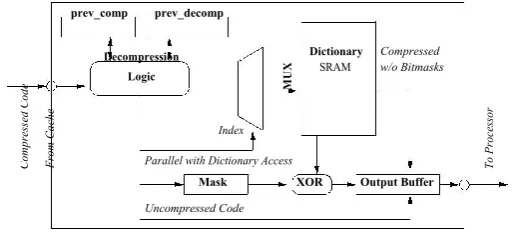
any stalling. Our design of the decompression engine is based on the one-cycle decompression engine (DCE) presented by Lekatsas et al. [4]. Figure 4 shows the design of our bitmask-based decompression unit. To expedite the decoding pro-cess, the DCE is customized for efciency, depending on the choice of bit-masks used. Using two 4-bit masks (Encoding 2 in Section 3), the compression algorithm generates 4 different types of encodings: i) uncompressed instruction, ii) compressed without bitmasks, iii) com-pressed with one 4-bit mask, and iv) compressed with two 4-bit masks. In the same manner, using one bitmask creates only 3 different types of encodings. Decoding of uncompressed or compressed code without bitmasks remain virtually identical to the previous approach.
For compressed encodings using bitmasks, our decompression unit provides two additional operations: generating an instruction-length (32-bit) mask, and XORing the mask and the dictionary entry. The creation of an instruction-length mask is straightforward as done by applying the bitmask on the specied position in the encoding. For example, a 4-bit mask can be applied only on half-byte boundaries (8 locations). If two bitmasks were used, the two intermediate instructionlength masks need to be OR-ed to generate one single mask. The ad-vantage of our design is that generating an instruction length mask can be done in parallel with accessing the dictionary, therefore generating a 32-bit mask does not add any additional penalty to the existing DCE.
The only additional time incurred in our design, compared to the previous one-cycle design, is in the last stage where the dictionary en-try and the generated 32-bit mask are
XOR-ed. We have surveyed the commercially manufactured XOR logic gates and found that many of the manufactures produce XOR gates with the propagation delay rang-ing from 0.09ns - 0.5ns, numerous under 0.25ns. The critical path of decompression data stream in [4] was 5.99ns (with the clock cycle of 8.5 ns). Additional 0.25ns satises the 8.5ns clock cycle constraint.
Compress
ed
Cod
e
F
ro
m
Ca
ch
e
prev_comp prev_decomp
Decompression
M
U
X
Dictionary Compressed SRAM w/o Bitmasks
Logic U n c o m p r e s s e d C o d e
To
Pr
oc
ess
or
Index Parallel with Dictionary Access
Mask XOR Output Buffer
Uncompressed Code
Figure 4: Decompression Engine for Bitmask Encoding
Our DCE can decode multiple instructions per cycle (with hardware support). If the codeword (with the dictionary index) is 10 bits, the encoding of instructions compressed only using the dictionary will be 12 bits or less. Instructions compressed with one 4-bit mask has the cost of additional 7 bits (total 18-19 bits). Therefore a 32-bit stream with any combination with a 12-bit code contains more than one instruction and can be decoded simultaneously. The best case is when a 32-bit stream contains two 12 bit encodings and prev comp register holds 4 bits of the compressed data from the previous cycle, the DCE engine has three instructions in hand that can be decoded concurrently.
4. EXPERIMENTS
section, we present experimental results using nine embedded applications for three target architectures. The nine benchmarks are collected from Mediabench and MiBench benchmark suites: adpcm en, adpcm de, cjpeg,
djpeg, gsm to,gsmun, mpeg2enc, mpeg2dec, andpegwit. We compiled thebenchmarks for three target architectures:TI TMS320C6x, MIPS, and SPARC. We used TI Code Composer Studio to generate binary for TI TMS320C6x. We used gcc to generate binary for MIPS and SPARC. We computed the compression ratio using the Equation (1). Our com-putation of a compressed program size includes the size of the com-pressed code as well as the dictionary and the small mapping table.
4.1 Results
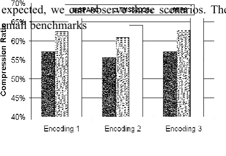
In Section 3, we presented our generic encoding format as well as three customized formats. Encoding 1 uses one 8-bit mask, Encod-ing 2 uses up to two 4-bit masks, and Encoding 3 uses 4-bit and 8-bit masks. Figure 5 shows the performance of each of these encoding for-mats using adpcm en benchmark for three target architectures. We used dictionary with 2K entries for these experiments. Clearly, the second encoding format performs the best by generating a compression ratio of 55-65%. Our experience with other benchmarks also suggests the same trend. We use the second encoding format (Encoding 2) for all the results presented in the remainder of this section.
Our technique performs well for different dictionary sizes. Figure 6 shows the efciency of our compression technique for all the nine bench-marks compiled for SPARC using dictionary sizes of 4K and 8K entries. As
expected, we can observe three scenarios. The small benchmarks
Figure 5: Compression Ratio for adpcm en Benchmark
such as adpcm en and adpcm de perform better with a small dictio-nary since a majority of the repeating patterns ts in the 4K dictio-nary. On the other hand, the large benchmarks such as cjpeg, djpeg, and mpeg2enc bene t most from the larger dictionary. The medium sizedbenchmarks such as mpeg2dec and pegwit do not bene t much from the bigger dictionary size. On an average, our technique generates 59% compression ratio.
Figure 6: Compression Ratio for Different Benchmarks
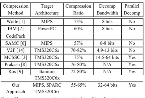
compression efciency of our technique is comparable to the state-of-the-art compression techniques (IBM CodePack[7] and SAMC[6]). However, due to the encoding complexity, the decompression band-width of those techniques are only 6-8 bits. As a result, they can not support one instruction per cycle decompression and it is not possible to place the DCE between the cache and the processor to take advan-tage of the post-cache design. Our decompression mechanism supports one instruction per cycle delivery as well as parallel decompression.
Table 2: Comparison with Various Compression Schemes
Compression Target Compression Decomp Parallel Method Architecture Ratio Bandwidth Decomp
Wolfe [1] MIPS 73% 8 bits No
IBM [7] PowerPC 60% 8 bits No
CodePack
SAMC [6] MIPS 57% 6-8 bits No
V2F [14] TMS320C6x 70-82% 4.9-13 bits No MCSSC [3] TMS320C6x 75% 14.5-64 bits Yes Prakash [8] TMS320C6x 76-80% N/A Yes
Ros [9] Itanium 72-80% N/A Yes
TMS320C6x
Our MIPS, SPARC 55-65% 32-64 bits Yes Approach TMS320C6x
Smaller compression ratio implies better compression technique.
5.CONCLUSION
An improved BCC algorithm is proposed in this paper. The encoding format was modified to enable the decompression engine to support multi-LUT access and use variable mask numbers to operate with the referenced instructions. Although the tag overhead to identify the codeword type is increased by 1 bit, the proposed method improves CR by over 7.5% with a slight hardware overhead. A new dictionary selection algorithm was also
proposed to improve the CR. The fully separated dictionary architecture was used to improve the performance of the decoder, and this architecture is better suitable to decompress instruction in parallel to increase the decompression bandwidth per cycle.
Multicore architecture has been a trend in modern embedded products. However, multicore systems require higher communication bandwidths either between the processors and the cache or between the cache and the memory, than singlecore systems. The design of a decompression engine is a new challenge for multicore systems. In the future studies, the design and implementation of a general multilevel separated dictionary decompression engine [23] with fu3
lly separated LUTs method and a parallel decompression engine will be investigated, for applying code compression to architectures with high bandwidth requirements, such as multicore architectures. Not only the CR, but also performance, power consumption, and communication bandwidth between the memory and the caches should be analyzed.
REFERENCES
1. Wei Jhih Wang and Chang Hong Lin ,Code Compression for Embedded Systems Using Separated Dictionaries”, in IEEE Transactions on very large scale integration (VLSI) systems 1063-8210 © 2015 IEEE
2. C. Lefurgy, P. Bird, I.-C. Chen, and T. Mudge, “Improving code density using compression techniques,” in Proc. 30th Annu.
ACM/IEEE Int.Symp. MICRO, Dec. 1997, pp.
3. S.-W. Seong and P. Mishra, “A bitmask-based code compression technique for embedded systems,” in Proc. IEEE/ACM
ICCAD, Nov. 2006, pp. 251–254.
4. S.-W. Seong and P. Mishra, “An efficient code compression technique using application-aware bitmask and dictionary selection methods,” in Proc. DATE, 2007, pp. 1–6.
5. M. Thuresson and P. Stenstrom, “Evaluation of extended dictionarybased static code compression schemes,” in Proc. 2nd
Conf.Comput.Frontiers, 2005, pp. 77–86.
6. H. Lekatsas and W. Wolf, “SAMC: A code compression algorithm for embedded processors,” IEEE Trans. Computer-Aided
Design Integr.Circuits Syst., vol. 18, no. 12, pp.
1689–1701, Dec. 1999.
7. S. Y. Larin and T. M. Conte, “Compiler-driven cached code compression schemes for embedded ILP processors,” in Proc. 32nd
Annu. Int.Symp. Microarchitecture, Nov. 1999,
pp. 82–91.
8. C. H. Lin, Y. Xie, and W. Wolf, “Code compression for VLIWembedded systems using a self-generating table,” IEEE Trans.
Very Large ScaleIntegr. (VLSI) Syst., vol. 15,
no. 10, pp. 1160–1171, Oct. 2007.
9. C.-W. Lin, C. H. Lin, and W. J. Wang, “A Power-aware codecompression design for RISC/VLIW architecture,” J. Zhejiang
Univ.-Sci. C(Comput. Electron.), vol. 12, no. 8, pp.
629–637, Aug. 2011.
10. T. Bonny and J. Henkel, “FBT: Filled buffer technique to reduce code size for VLIW
processors,” in Proc. IEEE/ACM Int. Conf.
CAD(ICCAD), Nov. 2008, pp. 549–554.
11. M. Ros and P. Sutton, “A hamming distance based VLIW/EPIC code compression technique,” in Proc. Compilers, Arch., Synth.
Embed.Syst., 2004, pp. 132–139.
12. J. Ranjith, N. J. R. Muniraj, and G. Renganayahi, “VLSI implementation of single bit control system processor with efficient code density,” in Proc. IEEE Int. Conf. Commun.
Control Comput. Technol. (ICCCCT), Oct.
2010, pp. 103–108.
Author’s Profile:
Ms.KONDURU.GOWT
HAMI
received B.Tech inElectronics and
Communication Engineering
from AUDISANKARA
Engineering College for woman, Nellore affiliated to the Jawaharlal Nehru technological university Anantapur in 2015, and pursing M. Tech in VLSI and Embedded systems from SKR College of Engineering affiliated to the Jawaharlal Nehru technological university Anantapur in 2015, respectively.
VADITE NANUKU NAIK as Asst Professor Department of ECE.