Low Profile Pattern Diversity Antenna Using Quarter-Mode
Substrate Integrated Waveguide
Kandasamy Krishnamoorthy1, *, Basudev Majumdar1, Jayanta Mukherjee1, and Kamla P. Ray2
Abstract—In this paper, a pattern diversity antenna, capable of radiating broad side as well as conical radiation patterns using quarter mode substrate integrated waveguide sub-array, has been presented. The pattern diversity is achieved by in-phase and out-of-phase excitation of the sub-array using a rat-race coupler feed network. The overall profile height of the proposed antenna is 3.17 mm. The measured performance of the antenna, in terms of return loss, isolation, gain and diversity performance in the
−10 dB impedance bandwidth, is in agreement with the simulated results. The proposed sub-array occupies 25% less area than the conventional microstrip antenna.
1. INTRODUCTION
The advancement in microwave wireless technology demands planar, low-profile and low-cost components and circuits. Substrate integrated waveguide (SIW) structures are promising candidates to realize low-loss, low-cost, and low-profile planar waveguide components and antennas [1–3]. It has the advantages of both conventional rectangular wave guide (RWG) and microstrip lines (high Q-factor, high power handling capacity, ease of interconnection, etc.). SIW based antennas have been proposed for frequency reconfigurability, polarization diversity and leaky wave antenna (LWA) applications [4–7]. Half mode SIW (HMSIW) has been proposed for 50% size reduction with similar performance as that of the corresponding SIW configurations [8]. The HMSIW based LWA is proposed in [9]. The quarter mode SIW (QMSIW) is realized by bisecting the HMSIW along the quasi magnetic wall, is reported in [10]. The QMSIW is also used as the antenna element for linear and circular polarization applications. The field distribution of QMSIW is almost similar to that of an original SIW. A Circular polarized (CP) planar antenna, based on the QMSIW sub-array, is presented in [11]. Each antenna element in subarray is fed with required amplitude and phase for the CP operation.
The pattern diversity antenna enhances the performance of the wireless systems such as high data rate, throughput and multipath fading mitigation. Various methods have been proposed to achieve the pattern diversity in antennas. In [12, 13], switching elements or varactor diodes are used on the radiator or feeding network for pattern reconfiguration. The switching diodes and varactor diode needs dc bias circuits, which increase the design complexity and fabrication cost of the antenna. In [14–16], a circular patch exited in TM11 and TM01 mode for broadside and conical pattern has been proposed. Shorting
pins are used to excite the two resonant modes at the same frequency in [14]. However, this configuration requires complex feed and matching network and also larger antenna size. A hybrid feed network has been proposed in [15] to excite the patch. In [17], the even and odd modes of a shorted patch have been exited using rat-race feeding network to get pattern diversity. The null scanning technique also proposed and implemented. Nevertheless, all the above designs employ air gap between the feed network and radiating patch, which increases the profile of the overall structure and the fabrication complexity
Received 3 June 2015, Accepted 12 August 2015, Scheduled 26 August 2015
* Corresponding author: Kandasamy Krishnamoorthy ([email protected]).
1 Department of Electrical Engineering, Indian Institute of Technology Bombay, Mumbai 400076, India. 2RFMS Division, Society
of the antenna. A fully planar antenna having radiation pattern diversity, based on QMSIW subarray, is proposed in this paper for the first time. The radiation pattern could be broad side or conical type depending on the excitation phase. A rat-race coupler is used to feed the antenna for the Pattern diversity. The proposed QMSIW sub-array based antenna, with pattern diversity, is planar, low profile, low loss and easily integrable with other planar circuits. In addition, each QMSIW element has the size of quarter wave length; this ensures compactness of the proposed antenna configuration. Additionally, this SIW antenna is less susceptible to electromagnetic interference. The return loss bandwidth and radiation characteristics of the proposed antenna are measured for comparison with simulated results. The antenna exhibits broad side and conical radiation pattern for in-phase and out-of phase excitations, respectively.
2. OPERATING PRINCIPLE AND ANTENNA GEOMETRY 2.1. QMSIW Principle of Operation
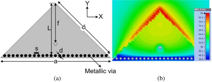
The QMSIW is a quadrant of a square SIW resonator as shown in Figure 1(a). Its resonant modes, field distribution and boundary conditions are analyzed in [10]. The QMSIW has two magnetic walls and one electric wall. The dominant mode of this isosceles right triangular wave guide is TM100/TM010[10].
The mode function of TM mode is given in (1) [10].
ϕT Mmn = cos
mπx
a
cos
nπy
a
−cos
nπx
a
cos
mπy
a
(1)
where, m and n are non-zero integers. Equation (1) satisfies the entire boundary conditions of TM mode when m=n. The QMSIW antenna is designed and simulated in CST microwave studio 2012 to verify the analytical model. The antenna is designed on the Rogers RT5880 substrate with thickness h= 1.574 mm, dielectric constantεr = 2.2 and low-loss tangent tanδ = 0.0011. The via hole diameter isd= 0.5 mm with the spacing between adjacent via holes ofs= 1 mm. The side lengths; a= 17.3 mm and b = 24.5 mm. The coaxial feed is located at f = 9.7 mm along the line of symmetry. The length L = 12.23 mm is chosen, which is quarter wavelength at the center frequency. Figure 1(b) shows the simulated electric field distribution of the antenna based on the QMSIW. The first resonance occurs at 5.17 GHz, which is corresponding to the TM100/TM010 mode of the QMSIW resonator.
(a) (b)
Figure 1. Quarter mode substrate integrated waveguide antenna. (a) Antenna geometry, (b) simulated electric field distribution of dominant mode.
2.2. Pattern Diversity Antenna Geometry
(a) (b)
(c)
(d)
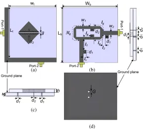
Figure 2. Configuration of the proposed pattern diversity antenna; (a) Top view, (b) bottom view, (c) side view, (d) ground plane;Lt=Wt= 60 mm,Lb =Wb = 65 mm.
The rat-race coupler is designed on the bottom side of the lower substrate to feed the sub-array and the top side is used as the ground plane as shown in Figures 2(b) and 2(c). The output ports of the rat-race coupler are directly connected to the QMSIW antenna sub-array through respective feed probe with diameter d= 0.7 mm. Two holes of diameterG= 2.4 mm is etched out in the ground plane as shown in Figure 2(d). The feed probes are connected to the antenna through ground plane holes. The rat-race coupler provides equal amplitude of in-phase and out-of-phase excitations when the signal fed to port 1 and port 2, respectively. The antenna subarray radiates conical and broadside pattern for in-phase and out-of-phase excitations, respectively. The rat-race coupler gives good isolation between two input ports. Two shorting lines with distances of l1 and l2 from rat-race ring are connected to the
port 1 and port 2 to match the port impedances to 50 Ω. It serves as a shunt inductance and by tuning length ls impedance matching has been achieved. The feed network has the following parameters:
lg = λg/4, ls = 4 mm, l1 = 12.7 mm, l2 = 3.5 mm, w1 = 2.65 mm, w2 = 4.5 mm, d2 = 1.4 mm and
λg= 40.5 mm.
3. SIMULATION AND MEASUREMENT RESULTS
The simulated electric current distribution of QMSIW sub-array is shown in Figure 3 for in-phase and out-of-phase excitations. The currents in the case of in-phase excitation have the opposite direction in the subarray patches, resulting in a null in the broadside, while they are in the same direction in the patches for the out-of-phase excitation giving maximum radiation at the broadside.
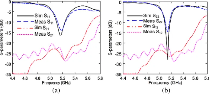
The fabricated prototype of the designed QMSIW subarray is shown in Figure 4. Figure 5 shows the measured and simulated s-parameters of the diversity antenna for port 1 and port 2. There is reasonable agreement between the simulated and measured results. The 10 dB return loss bandwidth from 5.1 GHz to 5.24 GHz for port 1 and 5.08 to 5.2 GHz for port 2 is observed. The isolation between the two feed ports is more than 22 dB.
Figure 3. Surface current distribution of the proposed quarter mode substrate integrated waveguide subarray pattern diversity antenna for in-phase and out-of-phase excitation.
(a) (b)
Figure 4. Fabricated prototype of the quarter mode substrate integrated waveguide pattern diversity antenna. (a) Antenna element on the top layer. (b) Feed network on the bottom layer.
(a) (b)
Figure 5. Measured and simulated S-parameters of the proposed quarter mode substrate integrated waveguide subarray pattern diversity antenna. (a) For In-phase excitation (port-1), (b) for out of-phase excitation (port-2).
gains in the range of operating bandwidth are presented in Figure 6(a). When the antenna radiation pattern is in broad side direction, the simulated and measured peak realized gains are 7.6 dB and 7.1 dB, respectively while in conical pattern mode, the respective simulated and measured antenna gains are observed to be 5.4 dB and 5.1 dB.
The measured gain is found to be less than the simulated gain of antenna along with feed network, which is attributed to the mismatch and connector losses in the measurement. The envelope correlation (ρe) and diversity gain (DG) are the important parameters for calculating the antenna performance of the diversity systems [18]. ρe can be calculated using the far-field parameters orS-parameters of the antenna. The envelope correlation for broadside and conical pattern antenna can be calculated from theS-parameters [19] by using
ρe = |S
∗
11S12+S∗S21S22|
(1−(|S11|2+|S21|2))(1−(|S22|2+|S12|2))
(2)
The Diversity gain (DG) is obtained [19] from (2) by using
DG= 10.481− |ρe|2 (3)
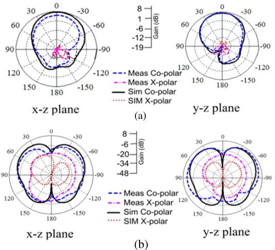
The simulated and measured far-field patterns of the antenna at 5.2 GHz for both input ports (in-phase and out-of-(in-phase excitations) are shown in Figure 7. For the input signal at port-2, the antenna radiation pattern is towards the +z direction (Figure 7(a)), while for port-1, conical radiation pattern with a null in the +z direction observed (Figure 7(b)). This pattern re-configurability is achieved by feeding the antenna structure in one port with other one match terminated with 50 ohm impedance. For conical pattern the measured cross polarization is found to be 25 dB below the co-polar radiation in the x-z plane and y-z plane. In the broadside mode of radiation the measured cross pole is around
−35 dB in both planes. The measured and simulated radiation pattern is stable for the entire −10 dB impedance bandwidth.
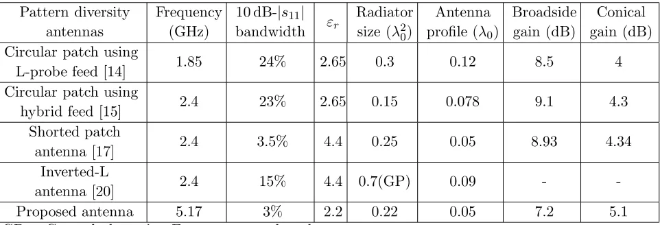
Table 1 presents the performance comparison between the proposed configurations and those of previously reported antennas. It is seen that the present configuration has comparatively low profile. In addition, radiation efficiency and gain are also improved.
(a) (b)
Figure 6. Measured and simulated gain, envelope correlation coefficient and diversity gain of the proposed pattern diversity antenna. (a) Gain plot, (b) diversity characteristics.
(a)
(b)
Table 1. Performance comparison of the proposed pattern diversity antenna with pervious literatures.
Pattern diversity antennas
Frequency (GHz)
10 dB-|s11|
bandwidth εr
Radiator size (λ20)
Antenna profile (λ0)
Broadside gain (dB)
Conical gain (dB) Circular patch using
L-probe feed [14] 1.85 24% 2.65 0.3 0.12 8.5 4
Circular patch using
hybrid feed [15] 2.4 23% 2.65 0.15 0.078 9.1 4.3
Shorted patch
antenna [17] 2.4 3.5% 4.4 0.25 0.05 8.93 4.34
Inverted-L
antenna [20] 2.4 15% 4.4 0.7(GP) 0.09 -
-Proposed antenna 5.17 3% 2.2 0.22 0.05 7.2 5.1
GP = Ground plane, λ0=Free space wavelength
4. CONCLUSION
A low-profile QMSIW sub-array based radiation pattern diversity antenna is proposed. The configuration is simulated and tested at 5.2 GHz. The antenna radiates conical and broad side pattern at fixed frequency when the subarray is excited with in-phase and out-of-phase excitation, respectively. The proposed structure produces pattern diversity with improved gain and less cross polarization level. This antenna, being low profile, is a good candidate for various applications of wireless communication.
REFERENCES
1. Deslandes, D. and K. Wu, “Integrated microstrip and rectangular waveguide in planar form,”IEEE Microw. Wireless Compon. Lett.,Vol. 11, No. 2, 68–70, Feb. 2001.
2. Wang, R., L.-S. Wu, and X.-L. Zhou, “Compact folded substrate integrated waveguide cavities and bandpass filter,” Progress In Electromagnetics Research, Vol. 84, 135–147, 2008.
3. Hong, W., K. Wu, H. Tang, J. Chen, P. Chen, Y. Cheng, and J. Xu, “SIW-like guided wave structures and applications,” IEICE Trans. Electron., Vol. E92-C, No. 9, 1111–1123, 2009.
4. Cheng, Y. J., “Substrate integrated waveguide frequency-agile slot antenna and its multibeam application,”Progress In Electromagnetics Research, Vol. 130, 153–168, 2012.
5. Sam, S. and S. Lim, “Frequency reconfigurable substrate integrated waveguide antenna,”
International Symposium on Antennas and Propagation (ISAP) 2012, 822–825, Oct. 29–Nov. 2,
2012.
6. Dong, Y. and T. Itoh, “Substrate integrated composite right-/left-handed leaky-wave structure for polarization-flexible antenna application,”IEEE Trans. Antennas Propag., Vol. 60, No. 2, 760–771, Feb. 2012.
7. Liu, J., D. R. Jackson, and Y. Long, “Substrate integrated waveguide (SIW) leaky-wave antenna with transverse slots,” IEEE Trans. Antennas Propag., Vol. 60, No. 1, 20–29, Jan. 2012.
8. Hong, W., B. Liu, Y. Wang, Q. Lai, H. Tang, X.-X. Yin, Y.-D. Dong, Y. Zhang, and K. Wu, “Half mode substrate integrated waveguide: A new guided wave structure for microwave and millimeter wave application,” Joint 31st International Conference on Infrared Millimeter Waves and 14th International Conference on Teraherz Electronics, 2006. IRMMW-THz 2006, 219–219, Sep. 18–22, 2006.
10. Jin, C., R. Li, A. Alphones, and X. Bao, “Quarter-mode substrate integrated waveguide and its application to antennas design,” IEEE Trans. Antennas Propag., Vol. 61, No. 6, 2921–2928, Jun. 2013.
11. Jin, C., Z. Shen, R. Li, and A. Alphones, “Compact circularly polarized antenna based on quarter-mode substrate integrated waveguide sub-array,” IEEE Trans. Antennas Propag., Vol. 62, No. 2, 963–967, Feb. 2014.
12. Sarrazin, J., Y. Mahe, S. Avrillon, and S. Toutain, “Pattern reconfigurable cubic antenna,” IEEE Trans. Antennas Propag., Vol. 57, No. 2, 310–317, Feb. 2009.
13. Nikolaou, S., R. Bairavasubramanian, C. L. Jr, I. Carrasquillo, D. C. Thompson, G. E. Ponchak, J. Papapolymerou, and M. M. Tentzeris, “Pattern and frequency reconfigurable annular slot antenna using pin diodes,” IEEE Trans. Antennas Propag., Vol. 54, No. 4, 439–448, Apr. 2006. 14. Yang, S. L. and K. Luk, “Design of a wide-band L-probe patch antenna for pattern reconfiguration
or diversity applications,”IEEE Trans. Antennas Propag., Vol. 54, No. 2, 433–438, Feb. 2006. 15. Wei, K., Z. Zhang, W. Chen, and Z. Feng, “A novel hybrid-fed patch antenna with pattern
diversity,” IEEE Antennas Wireless Propag. Lett., Vol. 9, 562–565, 2010.
16. Sun, L., W. Huang, B. Sun, Q. Sun, and J. Fan, “Two-port pattern diversity antenna for 3G and 4G MIMO indoor applications,” IEEE Antennas Wireless Propag. Lett., Vol. 13, 1573–1576, 2014. 17. Jiang, X., Z. Zhang, Y. Li, and Z. Feng, “A novel null scanning antenna using even and odd modes
of a shorted patch,”IEEE Trans. Antennas Propag., Vol. 62, No. 4, 1903–1909, Apr. 2014.
18. Meshram, M. K., R. K. Animeh, A. T. Pimpale, and N. K. Nikolova, “A novel quad-band diversity antenna for LTE and Wi-Fi applications with high isolation,” IEEE Trans. on Antennas Propag., Vol. 60, No. 9, 4360–4371, 2012.
19. Khaleghi, A., “Diversity techniques with parallel dipole antennas: Radiation pattern analysis,”
Progress In Electromagnetics Research, Vol. 64, 23–42, 2006.