Compact and High Selectivity Tri-Band Bandpass Filter Using
Multipath-Embedded Resonators
Shuai Yang*, Bian Wu, Cheng Zhu, Yi Wang, and Chang-Hong Liang
Abstract—In this paper, a novel compact tri-band bandpass filter (BPF) with compact circuit size and high passband selectivity has been presented and implemented using multipath-embedded resonator (MER). This filter includes two multipath-embedded stepped impedance resonators (SIRs), connected with stub-coupling at the symmetric plane. By tuning admittance ratio and length ratio of the multipath-embedded resonator, it can be designed at 1.84, 2.45, 3.05 GHz. Through internal edge-coupling and extemal zero-degree feed lines, a tri-band BPF can be achieved with compact circuit size, high passband selectivity and low insertion loss. The measured results validate the full-wave EM simulated results with good agreement.
1. INTRODUCTION
With the development of wireless communication, new consumer systems such as Long Term Evolution (LTE), Bluetooth, wireless local-area network (WLAN), and Worldwide Interoperability for microwave access (WiMAX) emerged into communication industry. The demand for integrating more than one communication standards (or modes) into a single wireless system is increasing. The tri-band transceiver [1] for GPRS applications, a typical example, tri-band bandpass filter serves as an important building block. Consequently, much research has been conducted, and various design approaches have been proposed.
For tri-band BPF designs, a typical method is to use stepped-impedance resonator (SIR) [2–4] and stub-loaded resonator (SLR) [5–7]. In [2, 3], a pair of asymmetric SIRs with parallel coupling arrangement was proposed to obtain the tri-band responses. Recently, a multimode SIR with 0◦ tapped-feed structure arrangement was proposed to achieve the tri-band responses [4]. Stub-loaded impedance resonator can also be used to design tri-band BPFs [5–7]. In [5], the resonant behavior of the stub-loaded SIR is analyzed, and after properly giving the impedance ratio and length ratio of the stub-loaded SIR, the required tri-band filter is obtained. In [6], a tri-band filter design is proposed where the DGS-based resonators result in first passband, and stub-loaded resonators contribute to the second and third bands. Different from other stub-loaded resonators, in [7], a tri-band BPF utilized a short-ended main transmission line and a centerly-loaded open stub. Other methods, such as multi-mode ring resonator [8], assembled resonators [9] and embedded bending stub resonators [10], are popular for the design of multi-band BPFs. In [8], a ring resonator with three pairs of degenerate modes was utilized for tri-band operation by controlling the perturbations of four open stubs. In [9], the assembled resonators constructed by a SIR and a common half-wavelength resonators were proposed to achieve the tri-band BPF. In [10], a tri-band BPF based on three embedded bending stub resonators (EBSRs) is proposed. Several methods for multi-band BPFs have been previously proposed [11–16]. As a very mature and popular technology, low temperature co-fired ceramic (LTCC) has attracted many people’s interest in
Received 21 October 2014, Accepted 14 November 2014, Scheduled 23 November 2014
* Corresponding author: Shuai Yang ([email protected]).
dual-band bandpass BPFs design in [11, 12]. In [13], the dual-mode square patch resonator is employed to achieve a dual-band bandpass filter. In [14], a dual-mode dual-band BPF is proposed by using asymmetric square loop resonators, and a pair of bent open-circuited stubs is installed to the loop as perturbation stubs. In [15, 16], the fractal geometry of a complementary single split ring resonator is used to design tri-band BPF.
In this letter, a compact tri-band BPF using multipath-embedded resonators (MERs) is proposed, which consists of two centrally connected the SIRs. The resonance characteristics of the proposed resonator are analyzed, and its design graph containing the normalized f2/f1 and length ratio of α with admittance ratio ofK is given. Based on the odd- and even-mode method analysis [17], the first three resonance frequencies corresponding to three paths can be determined according to given design specifications. To verify its performance, a tri-band BPF based on MERs is successfully designed and fabricated. The measured results validate the simulations.
2. TRI-BAND BANDPASS FILTER DESIGN AND ANALYSIS
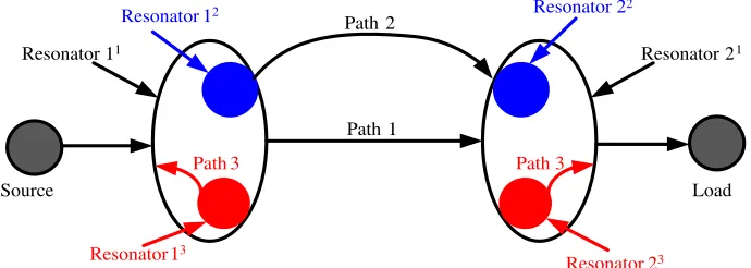
Figure 1 shows the coupling structure of the proposed filter. In comparison with conventional multi-passband filters, the filter only uses two coupled resonators to generate triple-multi-passband with high passband selectivity. The resonator includes three resonant paths at 1.84, 2.45, 3.08 GHz, as indicated by the superscripts of 1, 2 and 3 in Figure 1.
Path 1 Path 2 Resonator 12
Resonator 11
Resonator 22
Resonator 21
Resonator 13
Resonator 23
Source Load
Path 3 Path 3
Figure 1. Coupling structure of the proposed filter.
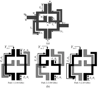
The layout of the proposed filter is shown in Figure 2(a). It is constructed by two steeped-impedance stub resonators (SISRs), and a common half-wavelength resonator is employed to achieve tri-frequency response. This novel resonator can be considered as a multipath-embedded resonator (MER), which includes three resonant paths as shown in Figure 2(b). Path 1 is designed at 1.84 GHz by using conventional half-wavelength SIRs and to be a main structure in the filter. Path 2 is designed at 3.08 GHz by using asymmetric half-wavelength SIRs. In our previous work [17], we used the even-odd-mode method to analyse the resonator mechanism of path 1 and path 2. We can derive that the resonant frequencies of even-mode (path 2) are well adjusted, whereas that of odd-mode (path 1) is fixed. Path 3 is designed at 2.45 GHz by using the quarter-wavelength SIRs. Path 2 and path 3 are embedded in a quarter-wavelength SIR (as path 1) so as to greatly reduce the circuit size. Three passbands are generated and controlled individually by tuning the structure parameters of each path. Path 1 and path 2 using stub-coupling in this filter, and path 3 couples with the main structure of the filter (path 1) in Figure 2(a).
The filter not only uses two coupled resonators to generate three passbands, but also produces four transmission zeros at each passband skirt. The transmission zeros are generated based on multipath propagation of cross coupling effects in the filter, and skew-symmetrical 0◦ feed structure [18] is introduced to achieve extra transmission zeros in the stop-band.
2
g t
3
g
1
g
W W1
2
W
2
W
2 2L
1
L
3
L
4
L
5
L
(a)
25
,
Z
1, 1 Z
1, 1 Z 1, 1
Z
22
,
Z 23
,
Z Z1, 4
1, 1 Z 1
in
Y
Y
in2Y
in3θ
θ θ
θ
θ
θ
θ
θ
Path 1 (1.84 GHz) Path 2 (3.08 GHz) Path 3 (2.45 GHz)
(b)
Figure 2. (a) Configuration and (b) each embedded resonant path of the proposed filter.
3.08 GHz) and quarter-wavelength SIRs ([(Z1, θ1), (Z2, θ5)] of path 3 at 2.45 GHz). According to the previous work [17], we set patch 1 at 1.84 GHz and patch 2 at 3.08 GHz. The resonant modes of the quarter-wavelength SIRs (path 3) can be derived by setting Y = 0, expressed as:
Yin3 =jY1
Ktanθ5+ tanθ1 1−Ktanθ1tanθ5
(1)
According to the resonance conditions Yin3 = 0, the resonance conditions of path 3 can be easily achieved as follows:
Ktan[(1−α)∗θ] + tan(α∗θ) = 0 (2)
θ=θ1+θ5 (3)
where the admittance ratioKand length ratioαare defined asK =Y2/Y1andα =θ1/(θ1+θ5). Several solutions for θ1 and θ5 are dependent on the choice ofK and α. Figure 3 shows relations between the normalized ratios of the first two resonance frequencies f2/f1 and length ratio of α with admittance ratio ofK for patch 3. It can be observed that maximums of f2/f1 occur when α= 0.5, thus these two resonant frequencies can be allocated more closely by tuning K <1.
Compared to the conventional design [2–4], normalized ratios of the first two resonance frequencies f2/f1 can be easily changed from 1 to 4. It is evident from Figure 3 that the normalized ratios f2/f1 have minimum value when 0 < K < 1 and maximum value when K > 1. This feature is useful for enhancing multi-band or wide-band filter.
3. EXPERIMENTAL VERIFICATION AND RESULT
0.2 0.4 0.6 0.8 1.0 1.5
2.0 2.5 3.0 3.5 4.0
f2
/
f1 K=0.1
K=0.3 K=0.5 K=0.7 K=1 K=1.3 K=1.5 K=1.7 K=1.9
α = θ /(θ + θ )5 1 5
Figure 3. Relationship between the normalized f2/f1and length ratioαwith different admittance ratioK.
Figure 4. Photograph of the fabricated BPF.
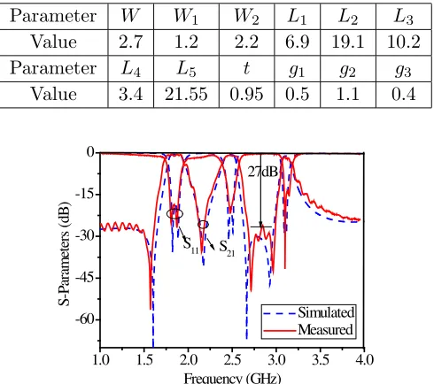
Table 1. Physical parameters of the filter (all in mm).
Parameter W W1 W2 L1 L2 L3 Value 2.7 1.2 2.2 6.9 19.1 10.2 Parameter L4 L5 t g1 g2 g3
Value 3.4 21.55 0.95 0.5 1.1 0.4
1.0 1.5 2.0 2.5 3.0 3.5 4.0 -60
-45 -30 -15 0
S
-P
ara
m
ete
rs (d
B
)
Frequency (GHz)
Simulated Measured S11 S21
27dB
Figure 5. Simulated and measured results of the proposed BPF.
Figure 4 shows a photograph of the fabricated BPF. The overall physical circuit size of the fabricated tri-band BPF is 27×33 mm2, alternatively, and it is equivalent to the size of 0.16λg×0.21λg, whereλgis the guided wavelength at the center frequency of first passband frequency. The simulated and measured frequency responses are illustrated in Figure 5. The simulation and measurement are accomplished by using IE3D and Agilent 8719ES network analyzer, respectively. The simulated and measured results show good agreement with each other over the frequency range from 1 to 4 GHz. The measured maximum insertion losses (IL) are found to be 0.51, 0.69, and 1.15 dB in the passbands centered at 1.84, 2.45, and 3.08 GHz, and their in-band return losses (RL) are 18.5, 18.7, and 25 dB, respectively.
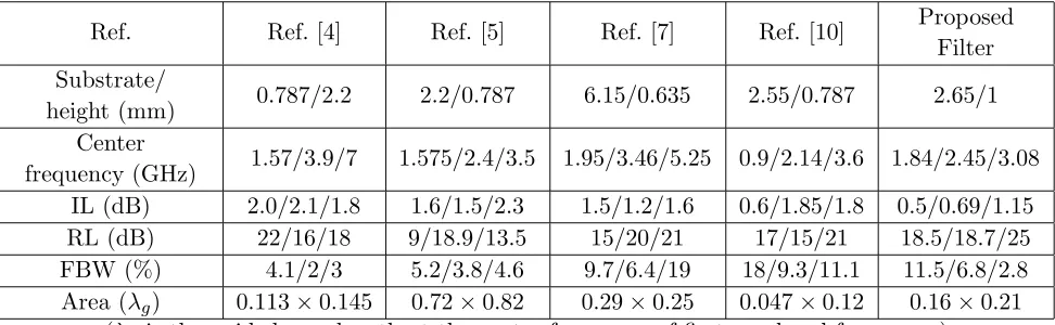
Table 2. Comparisons of the proposed filter with other reported tri-band filters.
Ref. Ref. [4] Ref. [5] Ref. [7] Ref. [10] Proposed
Filter Substrate/
height (mm) 0.787/2.2 2.2/0.787 6.15/0.635 2.55/0.787 2.65/1 Center
frequency (GHz) 1.57/3.9/7 1.575/2.4/3.5 1.95/3.46/5.25 0.9/2.14/3.6 1.84/2.45/3.08 IL (dB) 2.0/2.1/1.8 1.6/1.5/2.3 1.5/1.2/1.6 0.6/1.85/1.8 0.5/0.69/1.15
RL (dB) 22/16/18 9/18.9/13.5 15/20/21 17/15/21 18.5/18.7/25
FBW (%) 4.1/2/3 5.2/3.8/4.6 9.7/6.4/19 18/9.3/11.1 11.5/6.8/2.8 Area (λg) 0.113×0.145 0.72×0.82 0.29×0.25 0.047×0.12 0.16×0.21
(λg is the guided wavelength at the center frequency of first passband frequency.)
Table 2 summarizes the comparison of the proposed tri-band filter with other reported tri-band BPFs [4, 5, 7, 10]. It can be concluded that the proposed filter has the advantage of low insertion loss, high selectivity, compact size and high band-to-band isolation level.
4. CONCLUSIONS
This letter presents a new compact tri-band BPF using multipath-embedded resonators. The proposed MER can generate three resonant frequencies with high degree of freedom which essentially helps not only to create the transmission zeros by multipath propagation, but also to reduce the overall circuit size. The proposed MERs can provide more feasibility to control the resonant frequencies, and skew-symmetrical 0◦ feed structures is introduced to achieve steep skirt selectivity. The simple and effective design method and excellent performance make the proposed filter attractive for multiple-band wireless communications.
ACKNOWLEDGMENT
This work was supported by the National High Technology Research and Development Program of China (863 Program) No. 2012AA01A308, the National Natural Science Foundation of China (NSFC) under project No. 61271017 and FRFCU No. JB140226.
REFERENCES
1. Lin, Y.-S., C.-C. Liu, K.-M. Li, and C.-H. Chen, “Design of an LTCC tri-band transceiver module for GPRS mobile applications,” IEEE Trans. Microw. Thoery and Tech., Vol. 52, No. 12, 2718– 2724, Dec. 2004.
2. Chen, W.-Y., S.-J. Chang, M.-H. Weng, Y.-H. Su, and H. Kuan, “Simple method to design a tri-band tri-bandpass filter using asymmetric SIRs for GSM, Wimax and WLAN applications,” Microw.
Opt. Technol. Lett., Vol. 53, No. 7, 1573–1576, Jul. 2011.
3. Li, J., S. S. Huang, and J. Z. Zhao, “Design of a compact and high selectivity tri-band bandpass filter using asymmetric stepped-impedance resonators (SIRs),” Progress In Electromagnetics Research
Letters, Vol. 44, 81–86, 2014.
4. Liu, H.-W., Y. Wang, X.-M. Wang, J.-H. Lei, and W.-Y. Xu, “Compact and High selectivity tri-band tri-bandpass filter using multimode stepped-impedance resonator,” IEEE Microwave. Wireless
5. Chen, W.-Y., M.-H. Weng, and S.-J. Chang, “A new tri-band bandpass filter based on stub-loaded step-impedance resonator,” IEEE Microwave. Wireless Compon. Lett., Vol. 22, No. 4, 179–181, Apr. 2012.
6. Lai, X., C.-H. Liang, H. Di, and B. Wu, “Design of tri-band lter based on stub loaded resonator and DGS resonator,” IEEE Microwave. Wireless Compon. Lett., Vol. 20, No. 5, 265–267, May 2010. 7. Zhang, X. Y., L. Gao, Z. Y. Cai, and X. L. Zhao, “Novel tri-band bandpass filter using stub-loaded
short-ended resonator,” Progress In Electromagnetics Research Letters, Vol. 40, 81–92, 2013. 8. Luo, S., L. Zhu, and S. Sun, “Compact dual-mode triple-band bandpass filters using three pairs
of degenerate modes in a ring resonator,”IEEE Trans. Microw. Theory and Tech., Vol. 59, No. 5, 1222–1229, May 2011.
9. Chang, F.-C. and Q.-X Chu, “Design of compact tri-band bandpass filter using assembled resonators,”IEEE Trans. Microw. Theory and Tech., Vol. 57, No. 1, 165–171, Jan. 2009.
10. Peng, Y., L. Zhang, Y. Leng, and J. Guan, “A compact tri-band passband filter based on three embedded bending stub resonators,” Progress In Electromagnetics Research Letters, Vol. 37, 189– 197, 2013.
11. Zhang, Q., B.-Z. Wang, W.-Y. Yin, and L.-S. Wu, “Design of a miniaturized dual-band double-folded substrate integrated waveguide bandpass filter with controllable bandwidths,” Progress In
Electromagnetics Research, Vol. 136, 211–223, 2013.
12. Zhou, C., Y.-X. Guo, L. Wang, and W. Wu, “Design of compact dual-band filter in multilayer LTCC with cross coupling,”Progress In Electromagnetics Research, Vol. 135, 515–525, 2013. 13. Yeo, K. S. K. and A. O. Nwajana, “A novel microstrip dual-band bandpass filter using dual-mode
square patch resonators,” Progress In Electromagnetics Research C, Vol. 36, 233–247, 2013. 14. Deng, K., S. Yang, S.-J. Sun, B. Wu, and X.-W. Shi, “Dual-mode dual-band bandpass filter based
on square loop resonator,” Progress In Electromagnetics Research C, Vol. 37, 119–130, 2013. 15. Xu, H.-X., G.-M. Wang, Q. Peng, and J.-G. Liang, “Novel design of tri-band bandpass filter based
on fractal shaped geometry of complementary single split ring resonator,”International Journal of
Electronics, Vol. 98, No. 5, 647–654, May 2011.
16. Xu, H.-X., G.-M. Wang, and J.-G. Liang, “Novel designed CSRRs and its application in tunable tri-band bandpass filter based on fractal geometry,” Radioengineering, Vol. 20, No. 1, 312–316, Apr. 2011.
17. Yang, S., L. Lei, J.-Z. Chen, K. Deng, and C-H. Liang, “Design of compact dual-band bandpass filter using dual-mode stepped- impedance stub resonators,” Electronics Letters, Vol. 50, No. 8, 611–613, Apr. 10, 2014.
18. Tsai, C.-M. and S.-Y. Lee, “Performance of a planar filter using a 0◦ feed structure,” IEEE Trans.
Microw. Theory and Tech., Vol. 50, No. 10, 2362–2367, Oct. 2002.