International Journal of Advanced Research in Computer Science
RESEARCH PAPER
Available Online at www.ijarcs.info
Nulls Placement of Circular Array Antenna Using Adaptive Differential Evolution
Algorithm
Banani Basu
*Department of Electronics and Communication Engineering, National Institute of Technology,
Durgapur, India [email protected]
G. K. Mahanti
Department of Electronics and Communication Engineering, National Institute of Technology,
Durgapur,India
Anwesh Mukherjee and Vishal Gupta
Department of Electronics and Communication EngineeringNational Institute of Technology, Durgapur, India [email protected]; [email protected]
Abstract:The article describes the application of adaptive differential evolution (ADE) to optimize uniform circular array to produce radiation pattern with specified side lobe level (SLL) and null placement control. Two instances of null pattern synthesis are presented in this work. In the first problem ADE is used to synthesize multiple deep nulls at specific directions. In the second problem wide and deep nulls are generated at the angular sector of the arrival of broadband interferences. The optimization process is accomplished by perturbing the complex weights of the antenna element in the circular array. The simulation results show that it is possible to obtain an symmetric radiation pattern having deep and wide nulls on both sides of the main lobe with depth greater than -60dB. Proposed method is proved very efficient in solving the various problems of circular array antenna optimization.
Keywords:Adaptive Differential Evolution (ADE); Side lobe Level; Deep Nulls; Wide Nulls; Circular Array.
I. INTRODUCTION
Null pattern synthesis has an extensive use in communication since it is capable of suppressing interferences coming from specific directions. For broadband interferences, nulls are formed in the pattern at the wide angular sector in the direction of the arrival of the interferences.
A convenient way to solve the null pattern synthesis problems is the use of global stochastic optimization methods. Thus the metaheuristic approaches like genetic algorithm [1,2], ant colony optimization [3], particle swarm optimization (PSO) [4,5], differential evolution [6,7] and their derivatives are useful tools for these highly nonlinear optimization problems. The optimization techniques aim to find a set of excitations and antenna element positions that facilitate the radiation pattern to fulfill the stringent designing goals. The priori works related to null steering techniques is accomplished by controlling the complex weights [8,9], the amplitude only [10,11], the phase-only [12,13], and the position only of the array elements [14,15].
Literature [16,17] describes the synthesis of circular arrays using evolutionary algorithms.
In our paper we have presented two examples of null pattern synthesis. In the first example optimization algorithm is used to synthesize radiation pattern with desired side lobe level and multiple deep nulls at specific directions. In the second problem pattern is formed to place the deep nulls in the wide angular sector in the direction of the arrival of the broadband interferences. For both the cases side lobe level is kept at same value and the angular width of the main beam
between the first nulls is not allowed to exceed a maximum limit. Algorithm calculates a symmetric excitation (amplitude and phase) distributions to place the deep and wide nulls on both sides of the main lobe with depth greater than -60dB. Interference suppression with complex weights offers greater degrees of freedom in the solution space. An improved variant of a popular metaheuristic algorithm called differential evolution (DE) is used for designing the proposed optimization problem. In the adaptive algorithm, parameter values like scale factor and cross over rate are automatically tuned according to the objective function values produced by the donor vector and target vector during the same run.
II. METHODOLOGY
We consider a circular array of N uniformly spaced radiating elements at a distance 0.5λ apart along the circle of radius r in the x-y plane, as shown in Fig. 1. The elements in the array are assumed to be isotropic so that the radiation pattern of the array can be described by its array factor. We need to vary the current excitation amplitude and phase to keep the peak SLL below a desired level where first null beam width is not allowed to exceed a fixed value and achieve a null control at desired directions.
The expression of the array factor for the circular array can be written as follows:
(
)
∑
=− −
− =
N
1 n
n 0 0 n
ne {exp(jkr[sin cos( ) sinθ cos( )])}
I φ θ,
AF ψn θ φ φ φ φ
where
λ
π
2 = k ,π
2 Nd r = andN n
n
π
φ
= 2 , N is thenumber of array elements,
θ
∈
[
−
π
2
,
π
2
]
,φ
∈[
0,π
]
,λ
isthe wavelength at the design frequency,
d
is the inter-element spacing, In is the excitation current amplitudeand
ψ
n is the excitation phase of each element.Without loss of generality we may consider that peak of the radiation pattern is directed at (θ0,φ0)=(0,0).
The problem is now to find the set of excitation distributions with the proposed adaptive DE that will generate the array pattern with desired SLL and nulls at specific directions. To achieve the optimization task fitness function is formed as follows:
( )
2 2)
(
)
(
SLL
oSLL
dD
o kD
dFit
k
−
+
−
=
∑
θ
θ
(2)
SLL0= Obtained maximum side lobe level (dB) in the
entire theta domain except the main lobe and the angular regions considered for null placement. SLLd= desired value
of SLL in dB.
( )
k dBValue
of
(
k)
in
dB
o
AF
D
θ
=
θ
and θk is the direction of the nulls and Dd=desired null
depth.
Figure.1. Uniform Circular Array of N isotropic elements
III. OVERVIEW OF ADAPTIVE DIFFERENTIAL
EVOLUTION ALGORITHM
Differential evolution (DE) is a stochastic optimization problem that was introduced by Storn and Price [20-21]. Since inception DE is known as simple, robust and very fast global optimization technique over continuous spaces.
In each generation G, DE uses NP D-dimensional parameter vectors as a population as follows
]
,
,
,
,
[
1,, 2,, 3,, ,,,G iG iG iG DiG
i
x
x
x
x
X
K
r
=
(3) For each parameter there may be a definite region where better search results are likely to be found. The initial population should cover the entire search space constrained by the specified upper and lower bound xmax and xmin.
Hence we may initialize the j-th component of the i-th vector as
(
,max ,min)
, min
, 0 ,
,i j i j
(
0
,
1
)
j jj
x
rand
x
x
x
=
+
⋅
−
(4) where randi,j(0,1) is a uniformly distributed random number
lying between 0 and 1. This random initial population improves through mutation, crossover, and selection operations.
A. Mutation:
DE mutates and recombines the population to produce a population of NP trial vectors. In particular, differential mutation adds a scaled, randomly sampled, vector difference to a third vector.
− ⋅ +
= r G
G r i G best G
i X F X i X i
V
, ,
,
, 1 2
r r
r r
(5) The indices
r
1i andr
2i are mutually exclusive and randomly chosen integers. Fi is called scaling factor that istuned automatically depending on the value of the cost function generated by each vector.
If the objective function value of any vector nears the objective function value attained byXbest,G
r
, Fiis estimated as
follows. ∆ + ∆ ∗ = i i i J J F δ 8 .
0 (6)
where
δ
=
10
−14+
∆
J
i/
10
,∆
J
i=
J
(
X
i)
−
J
(
X
best)
and4
.
2
<
∆
J
iThe expression results a lesser value of Fi causing lesser
perturbation in the solution. So it will undergo a fine search within a small neighborhood of the suspected optima.
If ∆Ji>2.4 Fi is selected obeying the following relation.
(
Ji)
i
e
F
=
0
.
8
*
1
−
−∆ (7) Eq. (7) results a greater value of Fi that ultimately booststhe exploration ability of the algorithm within the specified search volume.
B. Crossover:
To increase the potential diversity of the population, crossover operation is introduced. In crossover the donor
vector exchanges its components with the target vector X→i,G
to obtain the trial vector
U
i,G. ≤ = = otherwise ) j j or Cr (0,1) (rand if , , rand i j i, , , , , G i j G i j G i j x v u (8) where randi,j[0, 1] is a uniformly distributed random
number and Cri is a constant called crossover rate.
[
D]
jrand∈1,2,K, is a randomly chosen index, which ensures
that Ui,G
r
gets at least one parameter from Vi,Gand does not
where Ji J
( ) (
Vi J Xbest)
r r
− =
∆ , Crmin=0.1,Crmax=0.7 and
Crconst=0.95
The parameter Cri is updated automatically depending on
the value of the cost function produced by the donor vector. If the donor vector yields a cost value lesser than the minimum value attained by that population, Cri value is
chosen high to pass more genetic information into the trial vector otherwise it remains small. Cri is determined
accordingly.
C. Selection:
Selection decides whether the target vector survives to the next generation or not. The trial vector is compared with the target vector using the following criterion.
(
)
(
)
(
)
(
)
> ≤ =
+
G i G
i G
i
G i G
i G
i G
i
X J U
J X
X J U
J U
X
, ,
,
, ,
, 1 ,
if
if
r v
r
r r
r r
(10) If the trial vector has an equal or better objective value then it replaces the corresponding target vector in the next generation. Otherwise the target is retained in the population. DE is an elitist method since the best population member is always preserved and the average objective value of the population will never deteriorate.
IV. RESULTS AND DISCUSSIONS
The ADE algorithm presented in the section III is applied for the synthesis of radiation pattern with desired SLL and null placement control. We consider a uniform circular array of 30 isotropic sources spaced at 0.5λ apart. We use symmetric excitation to excite the array in order to obtain the symmetric radiation pattern in both side of the main lobe.
For ADE we use the following parametric setup for both the designing problems.
a. Population size NP=50;
b. Maximum number of cycles =1000.
c. Maximum number of function evaluations = 50000. d. Scaling Factor F and Cross Over rate Cr are modified
[image:3.612.327.541.333.466.2]based on the fitness function of individual population as stated by eq.(6), (7) and (9).
Table I Symmetric current amplitude and phase distribution for multiple nulls placement
Element no.
Current amplitude
Current phase
1 & 16 0.44149 125.99
2 & 17 0.34563 -84.283
3 & 18 0.65367 159.58 4 & 19 0.19039 179.96 5 & 20 0.55123 157.63 6 & 21 0.28761 171.06 7 & 22 0.99772 161.19 8 & 23 0.85224 -154.73 9 & 24 0.99728 171.91 10 & 25 0.55715 -166.73 11 & 26 0.61486 163.89 12 & 27 0.076661 120.98 13 & 28 0.069083 -166.2
14 & 29 0.50619 91.224 15 & 30 0.70678 -106.15
In the first instance we try to find out the optimal pattern for the 30 elements array with desired maximum at 00 and multiple prescribed nulls at 420 and 780 respectively. It is obvious that image nulls would be imposed at -420 and -780 since the experiment considers symmetric excitation distribution. The peak SLL at the specified null directions is not allowed to exceed -60dB. Otherwise the desired SLL value is fixed at -20dB. ADE is used to optimize the objective function specified in Eq. (2). The dynamic range allowed for elements amplitude and phase perturbation is (0,1) and (-1800,1800) respectively. Table I shows the symmetric current amplitude and phase distribution to generate radiation pattern with desired SLL and multiple nulls. Symmetric radiation pattern obtained using the optimized data in theta domain is shown in Fig.2.
It is seen that the array pattern generated has maximum side lobe level equal to -20.05dB. Nulls are imposed at 780 and 420 with null depth equal to -61.25dB and -62.16dB respectively. The nulls become deeper with wider main beam width. Maximum allowable tolerance in the main beam broadening is chosen not more than 400 (FNBW) for this case.
[image:3.612.335.540.520.739.2]Figure.2. Normalized power pattern with multiple nulls
Table II. Symmetric current amplitude and phase distribution for wide null placement
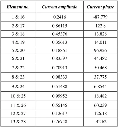
Element no. Current amplitude Current phase
1 & 16 0.2416 -87.779 2 & 17 0.86115 122.8 3 & 18 0.45376 13.828 4 & 19 0.35613 14.011 5 & 20 0.18861 96.926 6 & 21 0.83597 44.482
7 & 22 0.70913 50.468
8 & 23 0.98333 37.775
9 & 24 0.51488 6.8544
10 & 25 0.99952 18.482
[image:3.612.66.250.524.739.2]14 & 29 0.36512 107.14 15 & 30 0.23442 -17.456
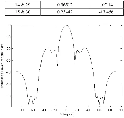
Fig.3. Normalized power pattern with wide null
In the second instance optimal pattern is generated using the same 30 elements array with desired maximum at 00 with desired wide nulls located within 550 to 700. It is obvious that the symmetric nulls would be imposed between -700 to -550 as the designed instance considers symmetric excitation distribution like the first case. It is expected that the ADE suppresses the array pattern more than -60dB at the specified null regions. Maximum side lobe level is constrained not to exceed -20dB. The null depth it is desired to keep -40dB relative to the peak SLL.
Table II shows the symmetric current amplitude and phase distribution to generate radiation pattern with desired SLL and wide nulls. The dynamic range allowed for elements amplitude and phase perturbation is (0,1) and (-1800,1800) respectively. Symmetric radiation pattern obtained in theta domain is presented in Fig. 3. Table III shows desired and obtained results for deep and wide null synthesis.
[image:4.612.43.269.559.699.2]The maximum side lobe level obtained in this case is equal to -19.17dB whereas the depth of the imposed wide null is found -60dB. SLL as well as depth of the nulls both can be improved with wider main beam width. Maximum allowable tolerance in the main beam broadening is kept within 400 (FNBW) like before.
Table III. Desired and obtained results for deep and wide null synthesis
Multiple Deep Nulls
Synthesis Wide Nulls Synthesis Design
Parameters
Desired Obtained Obtained Desired
Side Lobe
Level in dB -20.00 -20.05 -20.00 -19.17
AF at ±780 -60.00 -61.25 NA NA
AF at ±420 -60.00 -62.16 NA NA
AF from -700
to -550 and
550 to 700 NA NA -60.00 -60.00
V. CONCLUSIONS
Designing uniform circular antenna arrays with desired SLL and null placement control in specific directions is a challenging optimization problem in computational electromagnetics.
This paper illustrated the use of an improved variant of DE algorithm for the synthesis of the uniform circular array with desired side lobe level and null placement control. We formulated the design problem as an optimization task on the basis of a cost function that takes care of the maximum side lobe levels and the null control. The cost function is minimized satisfying both the constraints.
ADE was successfully used to optimize the excitation current amplitude and phase distributions of the array in order to generate an array pattern with desired specifications. Moreover the patterns, amplitude and phase distributions are all symmetric in nature that greatly simplifies the feed network.
Future research may focus on exploring the design of other array geometries and concentric circular arrays with ADE or some more improved population based metaheuristic algorithms.
VI. REFERENCES
[1]. Haupt, R.L, ”Thinned arrays using genetic algorithms”, IEEE Trans. Antennas Propagat.42, 993–999,1994. [2]. R.L.Haupt, "Adaptive Nulling with Weight Constraints",
Progress In Electromagnetics Research B, Vol. 26, 23-38, 2010.
[3]. S. A. Hosseini and Z. Atlasbaf, "Optimization of side lobe level and fixing quasi-nulls in both of the sum and difference patterns by using continuous ant colony optimization (ACO) method", Progress In Electromagnetics Research, Vol. 79, 321-337, 2008. [4]. Jin, N. and Rahmat-Samii, Y, “Advances in particle
swarm optimization for antenna designs: Real-number, binary, single-objective and multiobjective implementations”, IEEE Trans. Antennas Propag, 55, 556-567,2007.
[5]. N. N. Pathak, B. Basu, and G. K. Mahanti, "Combination of inverse fast fourier transform and modified particle swarm optimization for synthesis of thinned mutually coupled linear array of parallel half-wave length dipole antennas", Progress In Electromagnetics Research M, Vol. 16, 105-115, 2011.
[6]. N. I. Dib, S. K. Goudos, And H. Muhsen, "Application of Taguchi's Optimization Method And Self-Adaptive Differential Evolution to the Synthesis of Linear Antenna Arrays", Progress In Electromagnetics Research, Vol. 102, 159-180, 2010.
[7]. A. Chowdhury, A. Ghosh, R. Giri, and S. Das, "Optimization of antenna configuration with a fitness-adaptive differential evolution algorithm", Progress In Electromagnetics Research B, Vol. 26, 291-319, 2010. [8]. Karaboga, D., K. Guney, and A. Akdagli, “Antenna array
pattern nulling by controlling both the amplitude and the phase using modified touring ant colony optimization algorithm," Int. Journal of Electronics, Vol. 91, 241-251, 2004.
Progress In Electromagnetics Research, PIER 33, 167-182, 2001.
[10]. Guney, K. and M. Onay, “Amplitude-only pattern nulling of linear antenna arrays with the use of bees algorithm", Progress In Electromagnetics Research, PIER 70, 21-36, 2007.
[11]. Babayigit, B., A. Akdagli, and K. Guney, “A clonal selection algorithm for null synthesizing of linear antenna arrays by amplitude control", Journal of electromagnetic Waves and Applications, Vol. 20, No. 8, 1007-1020, 2006.
[12]. Haupt, R. L., “Phase-only adaptive nulling with a genetic algorithm", IEEE Transactions on Antennas and Propagation, Vol. 45, 1009-1015, 1997.
[13]. Mouhamadou, M., P. Armand, P. Vaudon, and M. Rammal, “Interference supression of the linear antenna arrays controlled by phase with use of SQP algorithm", Progress In Electromagnetics Research, PIER 59, 251-265, 2006.
[14]. Ismail, T. H. and M. M. Dawoud, “Null steering in phased arrays by controlling the element positions", IEEE Transactions on Antennas and Propagation, Vol. 39, 1561-1566, 1991.
[15]. Akdagli, A., K. Guney, and D. Karaboga, “Pattern nulling of linear antenna arrays by controlling only the element positions with the use of improved touring ant colony optimization algorithm", Journal of Electromagnetic Waves and Applications, Vol. 16, No. 10, 1423-1441, 2002.
[16]. Gourab Ghosh Roy, Swagatam Das, Prithwish Chakraborty, and Ponnuthurai N. Suganthan, "Design of Non-Uniform Circular Antenna Arrays Using a Modified Invasive Weed Optimization Algorithm", IEEE Transactions on Antennas and Propagation, Vol. 59, No. 1, 2011.
[17]. M. A. Panduro, C. A. Brizuela, L. I. Balderas, and D. A. Acosta, "A comparison of genetic algorithms, particle swarm optimization and the differential evolution method for the design of scannable circular antenna arrays", Progress In Electromagnetics Research B, Vol. 13, 171-186, 2009.
[18]. Storn, R. and Price, K. V. ”Differential Evolution–a simple and efficient heuristic for global optimization over continuous spaces”, J. Global Optimization,11, 341– 359, 1997.