International Journal of Advanced Research in Computer Science RESEARCH PAPER
Available Online at www.ijarcs.info
An Experimental Analysis of Aluminium Metal Matrix Composite using Al2O3/B4C/Gr
Particles
Raminder Singh Bhatia Mechanical Engineering Deoartment, SBBSIET,Padhiana, DisttJalandhar,Punjab
Kudlipsingh
Mechanical Egineering Department, SBBSIET,Padhiana, DisttJalandhar,Punjab
Abstract: The present work aims to develop hybrid Aluminium metal matrix composites (HAMC”S) by incorporating different types of reinforcements such that combination of best properties could be achieved. The metal base was selected was Aluminium alloy 12% Si and it is reinforced with varying weight percentage of alumina, graphite, and boron carbide. These AMC were developed by by using stir casting technique, in which predetermined reinforcement is added to the molten matrix and then slurry is stirred well to obtain desired castings. These castings were studied for microstructural behavior and subjected to mechanical testing to study the effects of various reinforcements. The analysis of interfaces obtained revealed that boron carbide interface cracks produced greater wettability of particles and perfect interface was observed between Alumina and graphite particles and this increased microhardness of surface with further reinforcements
I. INTRODUCTION
Aluminium and its alloys are one of the best materials suited for aerospace, mechanical and manufacturing industries where weight saving is of prime requirement. In addition to weight savings,Aluminium alloys and Aluminium metal matrix composites provides combination of mechanical properties such as high strength to weight ratios, higher stiffness, better wear resistance and damping capacities. Metal Matrix Composites (MMC) allowed property modifications of commercially available conventional materials. The domain of materials science has been diversified with the developments of composites and newer materials are developed for various applications of engineering and technology.
1.1 METAL MATRIX COMPOSITES
There are many definitions of metal matrix composites which are widely accepted worldwide and in general metal matrix composites are materials which consist of two or more materials phases with primary bulk phase of metal. The bulk metal material in which other materials are added is called matrix phase, whereas materials added to alter the properties are called reinforcements, which are in the form of particles or fibers and are dispersed in the metal matrix .Metals reinforced with hard particles such as boron carbide or aluminium oxide are called particulate metal matrix composites. If reinforcements are added in the form of long or short fibers such as carbon fibers, then fiber reinforced
composites are obtained. Further, fiber reinforced composites can be divided into laminate composites consisting of unidirectional, bi-directional or multi-directional mats, reinforced in metal matrix. Infiltration composites derived their name due to the processing method used for manufacturing metal matrix
composites. All the broadly classified metal matrix composites are processed by various routes and these routes are explained in further sections. The aim of research is to replace the conventional monolithic materials including aluminium alloys, ferrous alloys, titanium alloys and polymer based composites in several applications by low weight high strength AMCs which requires lower power for processing routes.
1.3 ALUMINIUM METAL MATRIX COMPOSITE (AMC)
Aluminium metal matrix composites (AMC’s) refers to the class of high performance, lightweight aluminium based material systems The AMC material system offers a combination of properties which are superior to many commercially available high strength monolithic materials. Over the years, AMC’s have been utilized in numerous structural, non-structural and functional applications of engineering and technology sectors. The main driving force for the utilization of AMCs in these sectors includes high performance, economics and environmental benefits. The key benefits of AMC’s in transportation sector includes lower weight which in turn effects the consumption, higher efficiencies, less noise produced, lower pollution and better shock absorbing capabilities.
TYPES OF ALUMINIUM METAL MATRIX COMPOSITES
The aluminium based metal matrix composites are divided into following categories depending upon the type of reinforcement (Surappa, 2003) and are discussed in detail in this section.
(a) PARTICLE-REINFORCED AMCs (PAMCs)
These composites contain the ceramic reinforcements in the form of oxides, carbides or borides (Al2O3, SiC, B4C, TiB2 etc.). The volume
than 30% and for electronic packaging applications volume fraction can be increased up to 70%. The mechanical properties of these particle reinforced composites are lower than whiskers or fibers reinforced composites but much better than unreinforced aluminium alloy. These composites are less expensive as compared to fiber reinforced and are isotropic in nature. PAMCs can further be subjected to number of secondary operations such as rolling, extrusion, forging and machining.
(b) WHISKER OR SHORT FIBRE-REINFORCED AMCs
When aspect ratio of reinforcements i.e. L/D becomes greater than 5, the reinforcement can be termed as whiskers or short fibers and composites reinforced with these reinforcements are called SFAMCs. The mechanical properties are better than particle reinforced composites..
(c) CONTINUOUS FIBRE-REINFORCED AMCs (CFAMCs)
The reinforcements having higher aspect ratios and in the form of continuous fibers are termed as continuous/long fiber reinforcements (alumina, SiC and carbon). These fibers can be in the form of long parallel unidirectional fibers or in the form of woven mats. These composites have highest tensile strength and elastic stiffness. These composites are utilized in maximum of the structural and heavy duty applications in the field of engineering.
(d) MONO FILAMENT-REINFORCED AMCs (MFAMCs)
Monofilaments are large diameter reinforcements (100 to 150 µm) fibres, usually produced by chemical vapour deposition (CVD) of either silicon carbide or boron into a core of carbon fibre or tungsten wire. The bending properties of monofilaments are low as compared to multifilament. Monofilament reinforced aluminium matrix composites are produced by diffusion bonding techniques, and is limited to super plastic forming aluminium alloy matrices. In CFAMC and MFAMC the load carrying members are fibers only and aluminium matrix serves the purpose of bonding the reinforcement in their respective places and act as stress transfer medium.
(e) HYBRID AMCs (HAMCs)
The hybrid aluminium metal matrix composites contains two or more type of reinforcements. Reinforcements in terms of mixtures of particles, whiskers and fibers with different weight percentage and varying sizes are utilized in aluminium matrix for multi functional properties.
PROCESSING ROUTES FOR AMC
The primary processing methods of aluminium metal matrix composites at industrial level is broadly classified into two categories:
1) Solid state processes 2) Liquid state processes
The process of stir casting of metal matrix composites was started with the introduction of alumina particles into aluminium melt by stirring molten aluminium alloys containing the ceramic powders. Stir casting is a process in which the distribution of reinforcing phases (usually in powder form) takes place into melt of molten metal (usually low melting point metals such as aluminium, magnesium, copper etc) by mechanical stirring. After proper mixing of melt and reinforcement, the resultant molten alloy, with ceramic particles, can be used for sand casting, die casting or permanent mold casting. The process of Stir casting is suitable when the volume fraction of reinforcement is up to 30%. The distribution of the particles in the molten matrix depends on the factors like geometry of the stirrer, placement of the mechanical stirrer in the melt, melting temperature, and the characteristics of the particles added. The process of stir casting is one of the general methods used for producing low cost aluminium metal matrix composites (Hashim et al., 1999) and allows manual insertion of reinforced particles using continuous stirring. The recent development in stir casting process is a two-step mixing process. In this process, initially the matrix material is heated up to its melting point. The melt is then cooled and kept in a semi-solid state. At this stage, the preheated particles are added and mixed into this semi-solid metal. This slurry is again heated to a fully liquid state and mixed thoroughly. Among all the well-established metal matrix composite fabrication methods, stir casting is the most economical and suitable method for mass production of metal matrix composites. The stir casting process is systematically described in Figure 2.
1.3 ADVANTAGES OF AMC
There are numerous advantages of aluminium metal matrix composites, however some of the important aspects which led the researchers to work in this field are reported below:
1. The most important property of aluminium based metal matrix composite is their higher strength per unit mass. The mechanical advantage of composites is determined by two parameters, specific modulus and specific strength.
=
𝐸𝐸
𝜌𝜌………(1)
2. The tensile strength of most of the steel grades decreases and material becomes brittle at lower temperature, but aluminium shows increases in tensile strength at low temperatures and decreases at high temperature.
3. Aluminium matrix composites are used in many thermal engineering applications due to higher thermal conductivity with lower weight. This property was further enhanced by the addition of conductive reinforcements such as graphite, which increases the material conductivity.
AMCs, which allowed these materials to be utilized in many automotive industries.
5. Aluminium is highly corrosion resistant metal. It reacts with the oxygen in the air to form an extremely thin layer of oxide. Further, reinforcements of ceramic materials enhance the corrosion resistance of AMCs.
6. Some of the important properties of aluminium composites are their reusability, excellent casting properties and machinabilty.
All these unique properties encouraged researchers to further explore the properties of aluminium alloys such that the area of applications can be widen up.
1.4 ALUMINIUM ALLOYS AS MATRIX
MATERIAL
Aluminium alloys are classified into two groups i.e. wrought alloys and cast alloys. Aluminium and its alloys are used in a variety of cast and wrought form and conditions of heat treatment. Cast aluminium alloy comes after sand casting, permanent mould casting, die casting, investment casting, centrifugal casting, squeeze casting and continuous casting such as Al-Si and Al-Mg alloys. The designation of Cast Aluminium alloy is shown in Table 2.
The second and third digits (xXX.x) are arbitrary numbers given to identify a specific alloy in the series. The number which following the decimal point indicates whether the alloy is a casting (.0) or an ingot (.1 or .2). A capital letter prefix indicates a modification to a specific alloy.
To meet the various requirements of industrial applications, aluminium is alloyed with copper, manganese, magnesium, zinc and silicon as major alloying elements. We shall first consider the 4-digit wrought aluminium alloy identification system. The first digit (Xxxx) indicates the principal alloying element. This alloying element has been added to the aluminium alloy and is often used to describe the aluminium alloy series, that is, 1000 series, 2000 series, 3000 series, up to 8000 series. Wrought aluminium alloys designation system is shown in Table 3. Further some of the alloys are heat treatable while some are non heat treatable. The heat treatable alloys acquire their optimum mechanical properties through a process of thermal treatment. The most common thermal treatments are Solution Heat Treatment and Artificial Aging. In the Solution Heat Treatment process, the alloy is heated to an elevated temperature (around 9900 F) and put the alloying elements or compounds into solution. This is followed by quenching, to produce a supersaturated solution at room temperature. Aging is the precipitation of a portion of the elements or compounds from a supersaturated solution in order to yield desirable properties. The aging process is of two types: aging at room temperature, which is (natural aging) and aging at elevated temperatures (typically about 320 Deg. F) termed artificial aging. The non-heat treatable alloys acquire their optimum mechanical properties through strain hardening. In strain hardening process, the strength is increases with the application of cold working. Table 4 shows some of the aluminium alloys with their industrial applications.
The role of reinforcements was already stated in the earlier text, however proper selection of reinforcements and their volume fraction is necessary for efficient performance of composites. A large number of reinforcements are available which have been utilized for bringing the metallurgical and mechanical changes in the aluminium alloys. Some of the reinforcements are added to enhance the tensile properties and on the other hand reinforcements are available which makes composites stronger in compression. Properties of the aluminium metal can be altered by selective addition of reinforcements. In present work properties of those powders will be discussed which will be used in the present work.
TYPE OF REINFORCEMENT
ALUMINA REINFORCEMENT (Al2O3)
Alumina is aluminium oxide which is a chemical compound of aluminium and oxygen with the chemical formula Al2O3.
It is the most commonly occurring aluminium oxides, and is specifically identified as aluminium (III) oxide Some of the important properties of alumina are:
• High hardness • High strength • High melting point
• Moderate densities and thermal conductivity
BORON CARBIDE REINFORCEMENT (B4C)
Boron Carbide is one of the hardest materials known, ranking third behind diamond and cubic boron nitride. It is the hardest material produced in tonnage quantities. Boron carbide powder is mainly produced by reacting carbon with B2O3 in an electric arc furnace, through carbothermal
reduction or by gas phase reactions. For commercial use B4C powders usually need to be milled and purified to
remove metallic impurities. Some of the key properties of boron carbide are:
• Extreme hardness • Good chemical resistance • Good nuclear properties
GRAPHITE REINFORCEMENT
Graphite is an allotrope of carbon and is considered as made up of entirely carbon atoms. As reinforcement graphite lowers the wear of material by providing lubrication and helps in the formation of tribological layer which prevents metal to metal contact.
CHARACTERIZATION OF AMC
EXPERIMENTAL SET UP FOR STIR CASTING PROCESS
The various equipments used for the casting of aluminium alloy are shown in Table 6 and brief description of various equipments is as follows:
1. Muffle Furnace 2. Graphite Stirrer 3. Graphite Crucible
Muffle furnace is used to heat the aluminium alloy material to its desired melting temperatures by conduction, convection, or blackbody radiation with the help of electrical resistance heating elements. A muffle furnace (sometimes, retort furnace) in historical usage is a furnace in which the subject material is isolated from the surrounding fuel and all of the products of combustion including gases and flying ash. In muffle furnace, desired metal of lower melting points are placed in graphite crucibles in form of raw pieces and temperature can be set through sensors. The furnace which is used for present work can operate up to a maximum temperature of 1100°C which is sufficient to melt aluminium alloy. The muffle furnace is shown in Figure 4 and schematic representation of stir casting process is shown in Figure 5.
Stir casting process allows manual insertion of reinforcements in the molten aluminium metal matrix. The uniform distribution of particles in the matrix is an essential requirement for obtaining isotropic composite. Agglomeration of reinforcements can seriously degrade the performance of the composites. To obtain uniform distributions, continuous stirring of slurry consisting of molten aluminium and reinforcements is required. Stirring is done in two ways either manual or by using mechanical motor connecting the stirrer. Better the stirring process, better dispersions will be obtained and better microstructures will be obtained. The essential requirements of stirrer material are that it should not contaminate the composite slurry and should not react or melt in the molten slurry. Graphite being hard and having higher melting
4. Power Hacksaw
It is a cutting machine having fine-toothsawwithabladeundertensionina frame and isusedforcuttingmaterials. It is powered by using electric motor and is used to cut the aluminium alloy into small pieces such that they can be feed into crucible kept into the muffle furnace
Acrucibleisarefractorycontainerusedforanumberofmodernla boratoryprocesses and itcanwithstandtemperatureshigh enoughtomelt metals. Melting of aluminium metals is carried out in graphite crucibles, which are kept in the furnace at high temperature. Earlier crucibles were made ofclay,buttheycanbemadeofanymaterialwithahighertemperat ureresistancethan the substances they are used to hold.
MATERIALS AND SAMPLE PREPARATION
The selected material for metal matrix is commercially available aluminium alloy Al-12%Si and its elemental composition is shown in Table 1.
Morphology Spherical Spherical Agglomerated
Flaked
Purity 99.5% 99.5% 99.5%
Table 2: Elemental composition of aluminium alloy Al-12%Si
Element Al Cu Mn Si+Fe Zn Percent
(%)
Bal. 0.05-0.2
0.05 max.
12.59 max.
0.1 max.
Aluminium alloy Al-12%Si is a commercially available aluminium alloy having excellent low weight and thermal stability properties. It is commonly used in heat exchanger fins, fins stock, dials, automobile parts such as pistons, cylinder liners and brake rotors, decorative parts, rivets, reflectors, and is extensively used in structural work. This alloy has excellent machinabilty, formability and can be readily welded to form complex structures. In market, sheets of this alloy are readily available in various forms of sheets, angles and bars. The reinforcements added were selected on the basis of literature review. The main parameters of selected reinforcements are shown in Table 3.
Table 3: Parameters of reinforcements
Parameters Alumina Boron Carbide
Graphite
Powder Size 30±10 µm 50±10 µm 80±10 µm
These reinforcements were added in the aluminium alloy to produced hybrid composites. The weight percentages of reinforcements were again selected from the previous work of researchers (Singh et al., 2014, Kumar et al., 2015) and the composition of reinforcements in various composites developed are shown in Table 9.
. This heating allowed removal of any moisture content and also increases the wettability of reinforced particles with matrix by enhancing the interfacial strength.
After proper addition and stirring of hybrid particulate reinforcements in the molten aluminium, the composite slurry is poured into a cast iron permanent mould of dimensions 160x65x35 mm. Cast iron permanent mould filled with the composite slurry is shown in Figure 8. Argon gas was supplied until the entire melt was poured into the permanent mould such that atmospheric contamination was restricted. The composites were allowed to solidify in atmospheric air and were taken out from the mould after solidification.
CHARACTERIZATION TECHNIQUES
are investigated and measured by using relevant techniques. It is one of the fundamental processes of understanding the material behavior in the field of materials science, without which the scientific and technical understanding of engineering materials is not possible.
The X-ray diffraction (XRD) is an analytical technique which is primarily used for phase identifications of a crystalline materials and it provide information on unit cell dimensions complete structure of material grains which forms the complete structure. This technique is highly used for detections of phases which have evolved during processing of materials. The quantitative analysis by this technique can provides the average bulk composition of materials microstructure. The X-ray diffraction technique is based on constructive interference of monochromatic X-rays and a crystalline sample. These X-rays are generated by a cathode ray tube which is filtered to produce monochromatic radiation which are collimated to concentrate and directed on the sample surface. The interaction of the incident rays with the sample produces constructive interference and a diffracted ray when conditions satisfy Bragg's Law (nλ=2d sin θ). This law relates the wavelength of electromagnetic radiation to the diffraction angle and the lattice spacing in a crystalline sample. These diffracted X-rays are then detected, processed and counted by receiving sensors. By scanning the sample
through the various ranges of 2θangles, all possible
diffraction directions of the lattice can be attained. The conversion of the diffraction peaks to d-spacing allows identification of the mineral because each mineral has a set of unique d-spacing. Typically, this is achieved by comparison of d-spacing with standard reference patterns. All diffraction methods are based on generation of X-rays in an X-ray tube. These X-rays are directed at the sample, and the diffracted rays are collected. A key component of all X-Ray diffraction is the angle between the incident and diffracted rays. The X-ray diffractometers consist of three basic elements: an ray tube, a sample holder, and an X-ray detector as
X-rays are generated in a cathode ray tube by heating a filament to produce electrons which are accelerated toward the target by applying a voltage and bombarded on the target material. When electrons have sufficient energy to dislodge inner shell electrons of the target material, characteristic X-ray spectra are produced which produces the information regarding the phases present in the material. In present work XRD is used to determine the phases of nickel powder, nickel rod, joints developed by microwave and TIG welded joints.
Scanning Electron Microscopy (SEM) Equipped With Energy Dispersive X-ray Spectroscopy (EDS)
The scanning electron microscopy (SEM) is a technique used to scan the surface area and is used to determine the microstructures of samples at higher magnifications. the small diameter of the primary electron beam. The detection and measurements of the energy permits elemental analysis (Energy Dispersive X-ray Spectroscopy or EDS). An EDS can provide rapid qualitative, or with adequate standards, quantitative analysis of elemental composition with a sampling depth of 1-2 microns. X-rays may also be used to
form maps or line profiles, showing the elemental distribution in a sample surface. Figure 10 shows the principle of SEM analysis and SEM equipment equipped with EDS.
1. Vickers Microhardness Testing
2. Tensile Testing
3. Wear Testing
[image:5.595.315.559.286.454.2]Tests were carried out under dry sliding conditions and at ambient temperature in open conditions. Samples were taken out from the cast composite and sample surface were prepared by polishing using 600, 800 and 1200 grit size silicon carbide emery papers followed by acetone cleaning. The parameters selected for dry sliding wear tests are shown in Table 4.
Table 4: Details of sliding wear test
Parameters Descriptions
Test setup Pin on disc tribometer
Wear specimen Cylindrical samples of various composites with initial roughness of 0.5µm.
Counter disc Material: EN31, Hardness: 70 HRc, Dia: 90 mm and Initial roughness 2µm
Sliding Distance (m) 2000
Sliding speed (m/s) 0.5-2.0 in steps of 0.5 Normal load (N) 5, 10, 15, 20, 25 Lubrication condition Dry
Temperature Room temperature (28˚C)
Initial and final weights were calculated using weighing machine having accuracy of 0.001 grams. Wear in terms of weight loss was calculated for the composites and data was presented in terms of wear rate given by Equation 3.
𝑊𝑊𝑊𝑊𝑊𝑊𝑊𝑊𝑊𝑊𝑊𝑊𝑊𝑊𝑊𝑊
=
𝑊𝑊𝑊𝑊𝑊𝑊𝑊𝑊𝑊𝑊𝑊𝑊𝑊𝑊𝑊𝑊𝑊𝑊𝑊𝑊
𝑆𝑆𝑊𝑊𝑆𝑆𝑆𝑆𝑆𝑆𝑆𝑆𝑆𝑆𝑆𝑆𝑆𝑆𝑆𝑆𝑊𝑊𝑊𝑊𝑆𝑆𝑆𝑆𝑊𝑊
𝑊𝑊𝑊𝑊
3⁄
𝑊𝑊
…...(3)The surface of worn out specimens will be analyzed by SEM for studying the wearing mechanisms of the composites. Results of all the characterizations carried out on the aluminium alloy and its composites are presented in the next chapter.
4.1 MICROSTRUCTURE ANALYSIS
It is observed that graphite and boron carbide got aggregated with each other and it becomes difficult to identify the particles as flakes of graphite covered the boron carbide particles.
Figure 1: SEM image showing the powder morphology of (a) Graphite, (b) Alumina and (c) Boron carbide
[image:6.595.39.296.110.179.2]From the studies of dispersion behavior, it was confirmed that composite containing 15% alumina, 5% graphite and 3% boron carbide show uniform dispersions in the matrix and no accumulation was observed. At higher magnifications the interface between reinforcements and matrix is clearly visible. Figure 16 shows SEM observations of interfaces of reinforcements with aluminium matrix. It was observed that graphite flakes and alumina particles form quality interfaces with aluminium matrix and reveals that interfaces are free from cracks and porosity defects; however, boron carbide particles shows the debonding and cracks at the interfaces due to lower wettability of particles.
Figure 2: Optical micrographs showing distribution behavior of reinforcements in (a) Al+ 5%Al2O3+1%Gr+1%B4C, (b)
Al+ 10%Al2O3+3%Gr+2%B4C, (c) Al+ 15%Al2O3 +5%Gr+
3%B4C (d) Al+20%Al2O3+8%Gr+4%B4C and (e) Al+
25%Al2O3 + 11%Gr +5%B4C composites
The SEM image at higher magnification showing the aggregation of reinforcement particles at one spot in the aluminium matrix is shown in Figure 17. Clustering of particles is visible at higher weight percentage of reinforcement in matrix and is caused due to increased particle interactions coupled with lower wettability of particles.
The elemental distribution in developed composite containing 15% alumina, 5% graphite and 3% boron carbide was studied by Energy Dispersive X-ray Spectroscopy.
The results of elemental distributions revealed that aluminium is the main element present in the composite and shows similar compositions at other sites. The presence of oxygen is due to the alumina reinforcement and the presence of carbon represents the graphite content with carbides of boron. The homogeneity of reinforcements in the matrix
allowed similar elemental composition at all the sites of developed composite.
4.1.2 XRD Analysis
The X-ray diffractions of various developed composites were carried out on X’PERT PRO of PAN ANLYTICAL
using Cu Kα radiations. The scanning was carried out at the
[image:6.595.316.577.240.373.2] [image:6.595.68.248.371.495.2]rate of of 1˚ mm-1in the 2θ range of 10–100˚. Typical XRD spectrums of composites are shown in Figure 19, which shows predominant peaks of aluminium matrix.
Figure 3: Typical XRD spectrums of (a) Al+
5%Al2O3+1%Gr+1%B4C, (b) Al+
10%Al2O3+3%Gr+2%B4C, (c) Al+ 15%Al2O3 +5%Gr+
3%B4C (d) Al+20% Al2O3 +8%Gr+4%B4C composites
With an increase in the content of reinforcements, peaks of alumina and carbon (representing graphite) can be seen. The position of high aluminium peaks corresponds to the values
of 2θ≈38.45˚, 45.28˚, 65.52˚ and 78.32˚. The presence of
alumina corresponds to the 2θ values of 29.28˚, 33.58˚ and 56.78˚. The peaks corresponding to graphite corresponds to
the 2θ values of 55.5˚ and 72˚. The presence of boron
carbide is shown by small peaks corresponds to the 2θ
values of 41.65˚ and 65.28˚.
4.2 MECHANICAL CHARACTERIZATIONS
After studying the microstructure of composites containing various reinforcements, it is essential to estimate the effect of reinforcements on mechanical properties. These properties further, determine the scope of material in various fields of engineering and technology. In the present work Vickers microhardness and tensile testing was carried out to estimate the effect of reinforcements on the strength of aluminium matrix.
Table 5: Vickers microhardness of aluminium and reinforced composite specimens
S.No. Alumina (Wt %)
Boron Carbide (Wt %)
Graphite (Wt %)
Average Vickers Microhardness (HV)
1 0 0 0 48±10
2 5 1 1 55±10
3 10 2 3 62±10
4 15 3 5 70.08±10
5 20 4 8 67±25
6 25 5 11 60.65±25
The results show that the composite specimen with 15% alumina, 5% graphite and 3% boron carbide shows highest hardness of 70.08±10 HV; however, with increasing the content of reinforcements, the variations in microhardness also increases. This variation is due to the non-uniform dispersion of reinforcements, which allowed agglomeration of particles and causes spots of variable hardness. Though, hardness of higher reinforced composites is much higher, but higher variations in different locations are obtained
Tests were carried out two times and average value is considered as a final value of tensile strength. It was observed that the tensile strength of AMC’s increased with increase in value of reinforcement up to some extent and on further increasing the content, strength decreases. The maximum tensile strength was observed in the composite containing 10% of alumina, 3% graphite and 2% of boron carbide. The decrease in strength on further increasing the reinforcement is due to the increased hardened phases such that interfacial cracking and agglomeration of particles allows premature failure. The presence of these hard particles also decreases the plastic deformation thus showing lower percentage elongation. The best composite (186.124 MPa) shows 54.82% higher strength than the base aluminium alloy (120.79 MPa). However, the decrease in percentage elongation of composite was ~37.74% in comparison to base alloy. Reinforcement in the matrix prevents the higher order deformations and contributes to the tensile strength by acting as load carrying members.
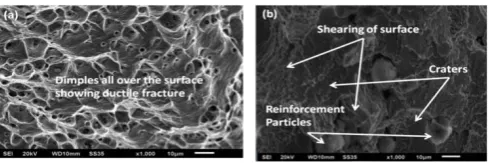
[image:7.595.39.279.88.238.2].
Figure 5: SEM image of fractures surface of (a) Aluminium Alloy Al-12%Si, (b) Aluminium composite containing 15% alumina+5% graphite +3% boron carbide.
4.3.1 Wear Behavior
Wear represents the material loss behavior of materials under sliding conditions and allows designers to study the interaction of materials under direct contact. It is one of the main parameters for development of parts having relative motion between them i.e. either sliding or rolling. If excessive losses of materials exist, then materials are said to have low wear resistance properties. A lot of research is going in this field such that high wear resistance materials are produced for applications in the field of surface engineering.
Figure 4: Wear rate of aluminium alloy and developed composites at varying normal load
spots. Figure 26 shows the optical micrographs showing the formation of uniform tribolayer and smearing of tribolayer at higher load.
It is observed that initially COF is higher in the initial stages due to interlocking of surfaces and higher frictional force required to slide the surface over one another. With an increase in the normal
V. CONCLUSIONS
The present work was based on the development of aluminium alloy Al-12%Si with the additions of different reinforcements in terms of varying weight percentages. Developed composites were characterized by microstructural analysis, mechanical testing in terms of microhardness and tensile strength, and study of dry sliding behavior. Following points can be concluded from the work carried out:
• The microstructural analysis revealed that uniform distribution of reinforcements were observed up to 15% of aluminium content with 5% graphite and 3% boron carbide. The SEM images revealed better interface was observed in alumina and graphite particles; whereas, due to lower wettability interfacial cracking was observed in boron carbide particles.
• At higher reinforcement levels, agglomeration was observed in the matrix which is due to the increased particle-particle interactions.
• The Vickers microhardness tests revealed that composite with 15%Al2O3 +5%Gr+ 3%B4C shows
highest microhardness value of 70.08±10 HV, which is 1.46 times better than base alloy. Highly reinforced composites shows higher variations due to the agglomeration of particles and the average value was lower than the 15% alumina reinforced composite.
[image:7.595.318.554.179.262.2] [image:7.595.40.285.621.702.2]alumina. The highest tensile strength was shown by 10%Al2O3 +3%Gr+ 1%B4C composite with
186.12 MPa and was 54.82% higher strength than the base aluminium alloy (120.79 MPa).
• The presence of higher amount of reinforcements in the matrix increases the discontinuities, which leads to lower strength. The hard phases present in the matrix prevents the higher order deformations and percentage elongation of material gets reduced.
• Tribological studies revealed that hardest composite revealed least wear and the presence of appropriate amount of graphite (5%) leads to uniform tribo layer. At higher loads and higher sliding velocity, the formed layer gets smeared; resulting in increased COF and wear rate of composites.
REFERENCES
[1] Alaneme, K. K. and Sanusi, K. O. (2015) “Microstructural Characteristics, Mechanical and Wear Behaviour of Aluminium Matrix Hybrid Composites Reinforced With Alumina, Rice Husk Ash And Graphite”, Engineering Science and Technology, An International Journal.
[2] Auerkari, P. (1996) “Mechanical and Physical Properties of Engineering Alumina Ceramics”, VTT Manufacturing Technology, Julkaisija-Utgivare Publisher, Finland.
[3] Chandramohan, D. and Marimuthu, K. (2011) “A Review on Natural Fibers. International Journal of Research and Reviews in Applied Sciences, vol. 8, 2, pp. 194–206.
[4] Hariprasad, T., Varatharajan, K., & Ravi, S. (2014) “Wear Characteristics of B4C and Al2O3 Reinforced with Al 5083 Metal
Matrix based Hybrid Composite”, Procedia Engineering, vol. 97, pp. 925–929.
[5] Hashim, J., Looney, L. and Hashmi, M. S. J. (1999) “Metal matrix composites: production by the stir casting method”, Journal of Materials Processing Technology, vol. 92–93, pp. 1–7.
[6]
http://en.wikipedia.org/wiki/Characterization_(materials_science), Accessed on 18/4/2015.
[7] Kala, H., Mer, K. K. S. and Kumar, S. (2014) “A Review on Mechanical and Tribological Behaviors of Stir Cast Aluminum Matrix Composites”, Procedia Materials Science, vol. 6, pp. 1951– 1960.
[8] Kalaiselvan, K., Murugan, N. and Parameswaran, S. (2011) “Production and Characterization of AA6061–B4C Stir Cast
Composite”, Materials & Design, vol. 32, 7, pp. 4004–4009.
[9] Kaw, A. K. (2005) “Mechanics of Composite Materials”, Second Edition, CRC press, Taylor & Francis, United States.
[10] Kumar, A. B., and Murugan, N. (2012) “Metallurgical and Mechanical Characterization of Stir Cast AA6061-T6-AlNp Composite”, Materials and Design, vol. 40, pp. 52–58.
[11] Kumar, A., and Singh, S. (2013) “Analysis of mechanical properties and cost of glass/jute fiber-reinforced hybrid polyester composites”, Proceedings of the Institution of Mechanical Engineers, Part L: Journal of Materials: Design and Applications. (Article in press) doi:10.1177/1464420713507915
[12] Kumar, V. G. B., Rao, C. S. P. and Selvaraj, N. (2012) “Studies on Mechanical and Dry Sliding Wear of Al6061–SiC Composites”, Composites Part B: Engineering, vol. 43, 3, pp. 1185–1191.
[13] Miranda, G., Buciumeanu, M., Carvalho, O., Soares, D. and Silva, F. S. (2015) “Interface Analysis and Wear Behavior of Ni Particulate Reinforced Aluminum–Silicon Composites Produced by PM”, Composites Part B: Engineering, vol. 69, pp. 101–110.
[14] Mohammad Sharifi, E., Karimzadeh, F. and Enayati, M. H. (2011) “Fabrication and Evaluation of Mechanical and Tribological Properties of Boron Carbide Reinforced Aluminum Matrix Nanocomposites”, Materials & Design, vol. 32, 6, pp. 3263–3271. [15] Naidu, A. L., Sudarshan, B. and Krishna, K. H. (2013) “Study On Mechanical Behavior Of Groundnut Shell Fiber Reinforced Polymer Metal Matrix Composities”, International Journal of Engineering Research & Technology, vol. 2, 2, 2013, pp. 1-6.
[16] Niranjan, K. and Lakshminarayanan, P. R. (2013) “Dry Sliding Wear Behaviour of In Situ Al–TiB2 Composites”,
Materials & Design, vol. 47, pp. 167–173.
[17] Ravindran, P., Manisekar, K., Narayanasamy, P., Selvakumar, N. and Narayanasamy, R. (2012) “Application of Factorial Techniques to Study the Wear of Al Hybrid Composites with Graphite Addition”, Materials & Design, vol. 39, pp. 42–54.
[18] Sharma, A., Garg, M., and Singh, S. (2015) “Taguchi Optimization of Tribological Properties of Al/Gr/B4C Composite”,
Industrial Lubrication and Tribology, vol. 67, 4. (Accepted Article).
[19 Singh, S., Singh, G., Kumar, L. and Singh, S. (2015) “Microstructural analysis and tribological behavior of aluminum alloy reinforced with hybrid alumina / nanographite particles”, Proceedings of the Institution of Mechanical Engineers, Part J: Journal of Engineering Tribology, vol. 229, 5, pp. 597–608.
[20] Srinivas, K., and Bhagyashekar, M. S. (2014) “Wear Behaviour of Epoxy Hybrid Particulate Composites”, Procedia Engineering, vol. 97, pp. 488–494.
[21] Stevulova, N., Kidalova, L., Junak, J., Cigasova, J., and Terpakova, E. (2012) “Effect of Hemp Shive Sizes on Mechanical Properties of Lightweight Fibrous Composites”, Procedia Engineering, vol. 42, pp. 496–500.
[22] Su, H., Gao, W., Feng, Z. and Lu, Z. (2012) “Processing, Microstructure and Tensile Properties of Nano-Sized Al2O3
Particle Reinforced Aluminum Matrix Composites”, Materials & Design, vol. 36, pp. 590–596.
[23] Surappa, M. K. (2003) “Aluminium matrix composites: Challenges and opportunities”, Sadhana, vol. 28, 1-2, pp. 319–334.