DOI: http://dx.doi.org/10.26483/ijarcs.v8i7.4574
Volume 8, No. 7, July – August 2017
International Journal of Advanced Research in Computer Science
RESEARCH PAPER
Available Online at www.ijarcs.info
ISSN No. 0976-5697
DISPERSION COMPENSATION AND SNR ENHANCEMENT IN MULTI-GBPS
WDM OPTICAL SYSTEMS USING MULTI STAGE EDFA
Abha Jain
M. Tech Scholar ( Digital Communication) Geetanjali Institute of technical Studies Udaipur
Anurag Paliwal
Assistant Professor (Digital Communication) Geetanjali Institute of Technical Studies Udaipur
Navneet Agrawal
Assistant Professor (Digital Communication) CTAE, Udaipur
Abstract: Fiber optic systems are of the backbone to modern day communication networks. The high bandwidth and data rates provided by fiber optics con truly be utilized by employment of WDM (wavelength division multiplexing) techniques. The WDM system is able to cater to a pleoethera of integrated broadband services combining voice, data, video, multimedia services and VAS (Value Added Services). WDM system long widely used in large distance lines suffers from problems such as a dispersion and attenuation which results degraded system performance. Dispersion compensation and optical power amplification are essential parameters in WDM systems. This work is about exploitation of multistage EDFA( Erbium Doped Files Amplifier) system to enhance power and reduce dispersion and achieve higher SNR(Signal Noise Ratio) as composed to signal EDFA of some source power. It is also imperative that by placement of stoger of EDFA pre and post FBG, allow for an order of magnitude increase in SNR and achieve excellent DC (Dispersion Compensation) in WDM systems.
Keyword: Optical fiber, WDM system, FBG, DC, multistage EDPA, pre and post FBG EDPA
I. INTRODUCTION
Optical fiber
The latest advancement which transmits data and prepared for transmitting messages module onto light waves. With uses glass (or plastic) strings (fibers) to transmit. A fiber optic connection contains a store of glass strings, each of which is prepared for transmitting messages adjust onto light waves.[1]
Wavelength Division Multiplexing
In fiber optic correspondence structure, wavelength-division multiplexing (WDM) is an advancement which multiplexes different optical transporter signals onto a lone optical fiber by using assorted wavelength (i.e. tones) of laser light. This method enables bidirectional trades more than one strand of fiber, and what's more duplication of utmost. A WDM structure uses a multiplexer at the transmitter to unite the signs, and a de-multiplexer at the receiver to part them isolated. With the right kind of fiber it is possible to have a device that do both at the same time and can fill in as an optical incorporate drop multiplexer. This is consistently done by usage of optical-to-electrical-to-optical (O/E/O) translation at the very edge of the vehicle sort out, thusly permitting cover operation with existing equipment with optical interfaces.
Dispersion Compensation Fiber (DCF)
Electronic balance strategies are utilized as a part of technique. Since there is immediate recognition at the receiver, direct contortions in the optical space, e.g. chromatic scattering, are converted into non straight mutilation after optical - to-electrical change. It is because of reason that the idea of
Non linear channel demonstrating actualized. For this mostly bolster forward equalizer (FFF) and choice criticism equalizers (DFE) structures are utilized. EDC appears down the speed of correspondence since it backs off the computerized to analog conversation.
Fiber Bragg Grating (FBG)
Optical fiber bragg grating (FBG) has as of late discovered a pragmatic application in remuneration of scattering broadening in long-haul correspondence. In this, chirped fiber grinding (CFG) is favored. CFG is a little all-fiber inactive gadget with low addition misfortune that is perfect with the transmission framework and CFG's scattering can be effortlessly balanced. CFG ought to be situated in-line for optical outcomes. This is the favored method due to its points of interest including little impression. Low addition misfortune scattering slant remuneration and unimportant non-straight impacts. Be that as it may, the design utilizing FBG is mind boggling Misinterpretation. [2, 3]
What is EDFA?
Erbium-doped fiber enhancer (EDFA) is an optical repeater gadget that is used to support the power of optical signs being helped through a fiber optic interchanges framework. An optical fiber is doped with the uncommon earth component erbium so that the glass fiber can assimilate light at one recurrence and radiate light at another recurrence.
Working Principles of EDFA
nm), it is propelled to a long-lifetime halfway state, at that point it rots back to the ground state by emanating light inside the 1525-1565 nm band. The Erbium can be either pumped by 980 nm light, in which case it goes through an unsteady short lifetime state before quickly rotting to a semi stable state, or by 1480 nm light in which case it is specifically eager to the semi stable state. Once in the semi stable state, it rots to the ground state by producing light in the 1525-1565 nm band. This rot procedure can be animated by prior light, in this manner bringing about enhancement. The working standards of EDFA are appeared in the Figure 1.
Figure 1: The working standards of EDFA
Basics design of EDFA
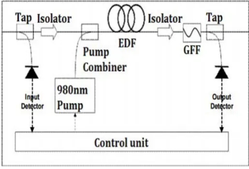
EDFA design is mostly made out of an EDF, a pump laser, and a segment (frequently alluded to as a WDM) for consolidating the flag and pump wavelength so they can proliferate all the while through the EDF. On a basic level, EDFAs can be composed to such an extent that pump vitality engenders an indistinguishable way from the flag (forward pumping), the other way to the flag (in reverse pumping), or both heading together. The pump vitality may either be 980 nm pump vitality, 1480 nm pump vitality, or a blend of both. For all intents and purposes, the most widely recognized EDFA setup is the forward pumping design utilizing 980 nm draw vitality, as appeared in the Figure 2. [4, 5, 6, 7]
Figure 2: The EDFA setup with 980 nm pump vitality
II. LITERATURE REVIEW
This article concentrates on the production of a four-channel WDM (Wavelength Division Multiplexing) framework utilizing SOA (Semiconductor Optical Enhancer) at the speed
of 10 Gbps and the dispersing of 1nm. In making an optical system it is important to use programming devices reproducing a genuine optical system under the given conditions. Assessment of the optical line quality for the separate channel is performed on the premise of BER (Bit Blunder Rate). The aftereffect of the article is a WDM framework in a mimicked domain assessing BER at specific stream in SOA. The wavelengths thought about were of 1549 nm and 1550 nm at draw current in the SOA: 0.05 A, 0.1 A and 0.2 A. The thought itself of wavelength multiplexing in optical correspondence was at that point hypothetically outlined and portrayed in the second 50% of the 1960s. However, the pragmatic application took after numerous years after the fact for the most part because of a weakness in the innovation required for the get together. The primary research center transmission of two wavelengths in one fiber was effectively done in 1978 and as far back as then the WDM for viable application has been seriously created and enhanced. Presently the WDM frameworks are a typical piece of the foundation of transmitting innovations and one optical fiber transmits tens or up to several optical signs isolated from each other by various wavelengths. The entire WDM chain comprises of n optical sources and locators where for each utilized wavelength the transmitter regulates the transmitted flag. The point of this article was to find the ideal direct current in SOA in a WDM framework in light of the BER for the individual channel. Negligible piece blunder rate required for a line is 10-12 for optical correspondence frameworks. In the reproduction with SOA draw current of 0.05 A the estimation of BER was demonstrated deficient in the collectors RX-2 and RX-3 as the BER vacillated around 10-5. At a draw current of 0.1 A the BER for the recipient RX-2 demonstrated satisfactory for utilization in optical correspondence as its esteem was 10-12. While expanding the current in SOA to 0.2 A the BER deteriorated to 10-4. As indicated by hypothetical information and recreation tests it was conceivable to utilize a draw current of 0.1 An in SOA for the four-channel WDM framework with separating of 1 nm in C band. [8]
We tentatively show interestingly a bidirectional transmission up to 60-km of a 16-channel-WDM-PON at 10-Gb/s. An optical-spending plan more than 30-dB was gotten. This depended on self-seeded RSOAs and multi-level-tweak of RF signals.
[image:2.595.37.295.507.681.2]utilizing EDFAs. One of the appropriate and vital parts in optical correspondence framework is Fiber Bragg Grating (FBG). Uniform FBG is contemplated as a scattering compensator in any optical correspondence framework. The test system utilized is OPTISYSTEM 7.0 reproduction programming. Every one of the recreations are done in OPTISYSTEM 7.0 at 10 Gbits/sec and 210 km of transmission fiber. The recreated transmission framework has been broke down on the premise of various parameters such as BER, Q-calculate, Output control, Gain, Noise Figure and Eye tallness. In this paper, we have mimicked an optical transmission framework. When we watched scattering, we choose to repay it. For this reason, we utilized uniform FBG and reenact it. The framework has been examined for with and without FBG grinding and apodization capacities. We have broke down that uniform FBG gives better outcomes for yield energy of optical fiber at 10 Gbits/sec. For a long separation optical correspondence framework the scattering in optical fiber confines the execution. By the utilization of fiber bragg grinding the scattering is adjusted. The utilization of fiber bragg grinding upgrades the bit mistake rate and the Q-calculate. We can infer that the uniform fiber bragg grinding gives better Q-variable and Bit mistake rate than without FBG. In future this can be utilized for long separation optical correspondence with high information rates and low misfortune. [9]
A long reach and heartbeat width diminished radio over fiber design in light of self stage tweak is exhibited for duplex correspondence to serve radio get to units (RAUs). A duplex design that worked on rate of 1 Giga bits for every second has been checked and pondered on execution parameters. Most extreme work is expert to communicate information from focal office (CO) to versatile base station more than 40 Km SMF-28 and from base station (BS) to radio get to units over the fiber extend of 300m. Work is done to satisfy the requests of future era fast portable correspondence frameworks that provide food various RAUs at delayed separations. Beat width diminishment effectiveness is examined for scattering remuneration fiber and fiber boast gratings in the proposed engineering. A notable normal for intelligent semiconductor optical enhancer is squeezed into administration to convey information speed and savvy frameworks. Intelligent semiconductor optical intensifier (RSOA) serves the upstream radio get to units and limits the cost of ROF framework. Bidirectional radio over fiber transmission of signs over rational beat self stage balance dependent optical bearers era has been illustrated. Signs were transmitted at the aggregated pace of 1 Gbps in duplex RoF framework. This work concentrated on the practical way to deal with creates and convey motions in RoF design. We proposed a helpful and also skillful plan through the joining of nonlinearity based self stage adjustment, to slice the use and to offer a long achieve framework. Significant corruption in the RoF correspondence which constrains the achievement of delayed separation transmission is because of heartbeat expanding and between image impedance. Beat width decrease effectiveness is investigated for scattering remuneration fiber and fiber boast gratings in the proposed engineering. It is watched that framework works for 50Km with great quality when DCF is joined in the framework. Correlation uncovered that FBG is utilized for PWR yet DCF performs better than FBG. [10] With the disclosure of optical fiber there was an across the board unrest in the field of correspondence. Optical fiber
correspondence offers high information rate, security, adaptability, higher data transmission and so on. However variables, for example, scattering, weakening, dissipating and so on., enormously hamper its execution. In addition it's scattering that extremely harms the fast information transmission in optical fiber. Scattering makes the beat spread as it goes along the fiber and causing obstruction. There are different strategies for scattering pay. This examination is done to underline the impact of scattering and how to defeat it by utilizing FBG. Fiber Bragg Grating is one of the broadly utilized advances to repay scattering in optical fiber correspondence and here we have utilized FBG to remunerate scattering in a 80Gb/s WDM organize utilizing NRZ modulator at transmitter side and the outcomes in this manner acquired are thought about. The estimation of Q-component, eye tallness and bit blunder rate (BER) is resolved for every last channel and their esteems are looked at. In view of the examination, the transmission framework has been planned which comprises of laser light as the source, modulator, single mode optical fiber as the channel, Fiber Bragg grinding (FBG) as the scattering compensator at that point, the optical transmission. [11]
The most regularly utilized scattering pay fiber (DCF) innovation is considered. Three plans (Pre-compensation.post-remuneration, blend pay of Dispersion Compensation strategies for 40 Gb/s non-come back to Zero connection utilizing standard and scattering repaid fiber through FBG compensator to upgrade high information rate optical transmission. Goals is to build the quality variable ,fiber length and better educational in eye chart utilizing distinctive adjustments procedures. The reproduction results are approve by investigating the Q-element and Bit blunder Rate(BER) in the numerical simulator. A fiber boast grinding (FBG) is a standout amongst the most critical and appropriate segment in an optical correspondence framework. The utilization of trilled FBG has been contemplated as a scattering compensator in an optical correspondence framework. The recreation Results are approved by investigating the Q-calculate .According to test ,when Q=6,the BER is around 10-9; when Q=7,the BER is around 10-12.Input power is taken as 9-10 db,The corresponding BER is better. It is watched that the symmetrical-pay conspire performs superior to anything pre-,post –compensation plans for 8x40 Gb/s wdm framework. It is watched that the remuneration plans diminished the scattering suitably yet among post pay conspire lessened the aggregator fiber chromatic scattering to the most extreme conceivable develop. direct lesser estimation of fiber Bragg grinding scattering and greater estimation of laser normal power is good to the execution of the transmission framework. It can be understood that heartbeat was expanded and its energy is expanded subsequently of increment in the peep parameter which is the best volume. We have break down the 8 channel WDM framework at 40 Gbps for various scattering pay plans utilizing DCF. We watched that the symmetrical-pay plot performs superior to the pre and post-remunerations plans.[12]
III. METHODOLOGY
Introduction of Optic system
examination of these systems, which commonly fuse nonlinear devices and non-Gaussian disturbance sources, are exceptionally baffling and to an incredible degree time-genuine in this manner, these endeavors would now be able to simply be performed capably and feasibly with the help of forefront new programming gadgets. OptiSystem is an imaginative optical correspondence structure reenactment package that blueprints, tests, and advances in every way that really matters any kind of optical association in the physical layer of a far reaching scope of optical frameworks, from basic video broadcasting systems to intercontinental spines. OptiSystem is a stay singular thing that does not rely on upon other amusement frameworks. It is a structure level test framework in light of the viable showing of fiber optic correspondence systems. It has a proficient new propagation condition and a different leveled significance of sections and systems. Its abilities can be produced easily with the development of customer parts, and can be faultlessly interfaced to a broad assortment of mechanical assemblies. A broad Graphical UI (GUI) controls the optical part arrangement and netlist, fragment models, and presentation representations (see Figure 1 on page 10). The expansive library of dynamic and dormant sections joins down to earth, wavelength-subordinate parameters. Parameter clears empower you to analyze the effect of particular contraption particulars on system execution. Made to address the necessities of research analysts, optical telecom engineers, system integrators, understudies, and a wide grouping of various customers; OptiSystem satisfies the demand of the impacting photonics promote for a proficient and easy to-use optical structure design instrument.
Optic Framework is an extensive programming plot suite that engages customers to mastermind, test, and duplicate optical associations in the transmission layer of present day optical frameworks.
Optic Framework is a broad programming diagram suite that engages customers to mastermind, test, and reproduce optical associations in the transmission layer of current optical frameworks.
A broad Graphical UI (GUI) controls the optical part configuration and netlist, portion models, and presentation plans.
Optic Framework considers the arrangement computerization of in every practical sense any sort of optical association in the physical layer, and the examination of a broad scope of optical frameworks, from Entire arrangement Systems, Metropolitan Region Systems (Keeps an eye on) and Neighborhood (LANs). Optic Framework consolidates an expansive library of test optical diagram (.osd) records that can be used as configurations for optical arrangement wanders or for taking in a show purposes. Optic Framework limits can be connected with the development of customer parts, and can be faultlessly speak with a broad assortment of gadgets.[1,13,14,15]
Multi stage EDFA for optical power amplification
Optical fiber correspondence is a standout amongst the most solid, speediest and most secure broadcast communications innovations. In present day advancement, it has duplicated. Through several kilometers of handling and transmission of information, solid piece blunder rate is dependable. An optical
flag or light is transmitted through an optical fiber. Optical fiber correspondence is a standout amongst the most solid, speediest and most secure broadcast communications advances. In present day advancement, it has increased. Through many kilometers of handling and transmission of information, dependable piece blunder rate is solid. An optical flag or light is transmitted through an optical fiber.
In optical fiber correspondence, there is an issue of flag corruption amid the transmission of separation. To take out misfortune limits, utilize an optical enhancer. The optical speaker specifically enhances the transmitter optical flag without changing over it into electrical shape. On account of choosing the flag enhancement technique, the erbium doped fiber intensifier (EDFA) is favored. EDFA is the utilization of doped fiber as an increase medium to open up EDFA optical flag level upgraded optical enhancer, enhance the Q consider and decrease the BER. Accordingly, the general execution of the transmission plan, for example, WDM is expanded. In the EDFA, populace reversal is accomplished by optical pumping to get populace reversal, which can be adequately pumped with a laser having a wavelength of 980 nm or 1,480 nm and displaying a pick up in the district of 1,550 nm. Intensification is accomplished by excitation of photon outflow. The pumped lasers energize particles into higher energies, from which they can be weakened by the fortified emanation of photons at the flag wavelength back to the lower level. Along these lines, the flag is opened up toward its of travel. EDFA expands the scope of transmission. For better execution, utilize multi-channel and multi-level EDFA setups. The stage upgrade in the EDFA and enhanced the quality element (Q consider) and decreased the bit mistake rate (BER). Therefore, general framework execution is progressed. Multi-channel and multi-level EDFA design, including three, three-way, and so forth. By mimicking diverse multi-channel and multi-arrange EDFA designs, enhancements can be broke down
Proposed System Implementation In Optisytem
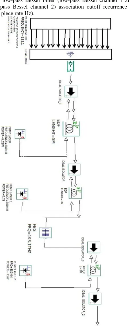
Programming Optisystem is utilized to outline EDFA in WDM frameworks. The framework comprises of 16 info signals (channels), perfect multiplexers, 4 isolators, pump lasers, erbium-doped fiber with a length of 5m, demultiplexer, photodetector PIN, low-pass bass Filter, as appeared in Figure 3.3.1. The framework is an adjusted balanced wavelength multiplex flag with a 100Ghz direct separating in the wavelength locale of 193.1 Thz. The energy of each channel is 0 dBm. Pumps at 980 nm are utilized to energize doping iotas at 0.75 W to a higher vitality level. Behind each isolator is erbium-doped fiber. First (isolator _1) trailed by EDF, pump laser recurrence of 980nm, energy of 0.75W, than there are additionally incorporate second isolator taken after by second EDF (Erbium doped fiber_1) with length of 5 m, and pump laser 1 with recurrence of 980nm and power 0.75W.
Next in the framework, the demultiplexer 1 * 2 is trailed by two photodetector pins for the photodetector stick _1 and the photodetector stick 2 and in addition each photodetector stick with low-pass Bessel Filter (low-pass Bessel channel 1 and low-pass Bessel channel 2) association cutoff recurrence = 0.75 piece rate Hz).
Fig: 3: Proposed System Architecture of multi stage EDFA with FBG
IV. RESULT
Single stage EDFA
The product Optisystem is utilized to outline the EDFA in the WDM framework. The framework comprises of 16 info signals (channels), a perfect multiplexer, isolators, a pump laser, erbium doped fiber with length of 15 m, demultiplexer, photograph finder PIN, low pass Bessel channel as appeared in Figure . The contribution of the framework is 16 evened out wavelength multiplexed motions in the wavelength locale of 193.1 Thz with100 Ghz channels dispersing. The energy of each channel is 0 dBm. The pumping at 980nm is utilized to energize the doped molecules to a higher vitality level with 0.75 W.
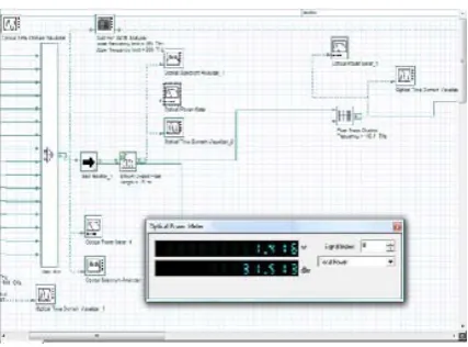
[image:5.595.236.554.300.656.2]In single stage EDFA case, when the signs goes through from perfect mux, and the signs which gone from perfect mux, the perusing will on first optical power meter ( optical power meter_4). The figure 6.1 demonstrates that estimation of signs on beginning of this operation. This is the primary meter to take note of the estimation of transmitted flag. Likewise called additionally optical transmitter.
Table 1: Value of signals on each optical power meter at different distance for single stage EDFA
S.No
.
Length
Of
Optical
Fiber
Input
Power
EDFA
Amplifi
er
After
FBG
Power
Received
Value
1
5KM
8.71
MW
1.419 W 1.379
W
1.096 W
2
10KM
8.71
MW
1.416 W 1.379
W
0.871W
3
15KM
8.71
MW
1.416 W 1.379
W
0.691 W
4
20KM
8.71
MW
1.416 W 1.379
W
[image:5.595.298.564.323.651.2]Fig 4: Optical Power Meter Reading
Multi Stage EDFA
The product Optisystem is utilized to plan the EDFA in the WDM framework. The framework comprises of 16 info signals (channels), a perfect multiplexer, four isolators, a pump laser, erbium doped fiber with length of 5 m, demultiplexer, photograph locator PIN, low pass Bessel channel as appeared in Figure 1. The contribution of the framework is 16 adjusted wavelength multiplexed motions in the wavelength area of 193.1 Thz with100 Ghz channels dividing. The energy of each channel is 0 dBm. The pumping at 980nm is utilized to energize the doped iotas to a higher vitality level with 0.75 W. The each isolator taken after by Erbium Doped Fiber. The fisrt isolator (isolator_1) trailed by EDF, draw laser with recurrence of 980 nm and power 0.75 W.
Table 2: Value of signals on each optical power meter at different distance for multistage EDFA
[image:6.595.316.548.66.209.2]In multi arrange EDFA case, when the signs goes through from perfect mux, and the signs which gone from perfect mux, the estimation of signs will be on first optical power meter ( optical power meter_4). The figure 6.5 demonstrates that estimation of signs on beginning of this operation. This is the main meter to take note of the estimation of transmitted flag. Additionally called likewise optical transmitter.
Fig 5: Optical Power Meter Reading
V. CONCLUSION
Conclusion
As shown above, the proposed system has been successfully implement and tested in optisystem simulation environment. As warranted, the proposed design is able to give superior signal to noise ratio (s) and noise figure (dB) as compare to single stage EDFA using with same output. As there is a significant rise in optical power as compared to single stage EDFA. Strategic placement of multistage EDFA, pre and post FBG, also enhance the some optical power input . As shown there is an average implement ofdB. In noise figure and mw in terms of optical power as proved by the result.
Table 3: Comparison between single stage and multi stage EDFA Results
S.NO
1
2
3
4
Lengt
h
5
10
15
20
Input
power
(MW)
8.71
8.71
8.71
8.71
Single
Stage
EDFA
Result
Receiv
ed
power
(MW
1.096
W
0.871
W
0.691
W
0.549
W
Avg.
Gain
17.90
50
16.44
88
15.06
56
13.68
59
Avg.
Noise
Figure
16.81 17.34
16
17.66
29
18.04
32
Output
OSNR
(DB)
38.36
2
37.84
37
37.52
32
37.14
35
S.No.
Length Of Optical
Fiber
Input Power
EDFA Amplif ier MW
After EDFA 1 Power
MW
After EDFA 2
(W)
Received Value W
1 5KM 8.71
MW
1.419 W
1.379 W
1.384 1.096 W
2 10KM 8.71
MW
1.416 W
1.379 W
1.384 0.871W
3 15KM 8.71
MW
1.416 W
1.379 W
1.384 0.691 W
4 20KM 8.71
MW
1.416 W
1.379 W
Multi
Stage
EDFA
Result
Receiv
ed
power
(MW)
1.099 0.873 0.693 0.551
Avg.
Gain
17.91
62
16.39
42
15.07
51
13.69
40
Avg.
Noise
Figure
7.610
4
8.137
0
8.462
0
8.850
4
Output
OSNR
(DB)
47.59
11
47.06
91
46.75
00
46.36
89
After comparison we find out the difference between single stage and multi stage result, multi stage recived power and output OSNR is more compare to single stage EDFA. In multi stage EDFA avg. Noise Figure is low compare to single stage EDFA and Avg. Gain is minor low. Thus all the whole experiment multi stage EDFA is give good output compare to single stage EDFA.
VI. FRUTURE SCOPE
WDM system are the life line of modern day optical fiber network. As depicted by our work, use of multistage EDFA in comparison to single stage. EDFA can provide for significant gains in terms of noise figure and optical power. This improve the perform once of a WDM system considerably as this is progressing research avenue , a lot more is required to cater the ever increasing bandwidth demand. Use of fives grating fibers can provide highly effective dispersion compensation. Also ongoing research in optical amplifier via enhances EDFA to use more sophisticated martial and component either than EDFA. Another research avenue is use of nanotechnology for building loss less optical amplifier. With the gamut of these new technologies on the verge to be introduce, we will see a lot happening in this decode.[12,13,16]
VII. REFERENCES
[1] Tomas Ivaniga, Lubos Ovsenik, Jan Turan “The Four-Channel WDM System Using Semiconductor Optical Amplifier” IEEE 2016.
[2] Ch. Pranavi& B. Geetha Rani “Uniform FBG as Dispersion Compensator in Optical Fiber Communications” IJIR 2017. [3] Pargat Singh&Dr.Charanjit Singh “A Carrier Generated
Self Phase Modulation Reliant Rof System Employing RSOA As Modulator For Upstream RAUs And Incorporating DCF, FBG For Dispersion Compensation” IJARCS 2017.
[4] P. S. Rath, Ajeet Satyam, Diwakar Mani Jha, Iftekhar Khalid “Performance Analysis of Long Fiber Optic Link using Fiber Bragg Grating for Dispersion Compensation” IJESC 2017.
[5] RupinderKaur, Mandeep Singh“Analysis on Dispersion Compensation with DCF based on Optisystem-A Review” IJOES 2016.
[6] Sachindev, Col.(Dr.) Suresh Kumar “Dispersion Compensation in Optical Fiber Communication using Bragg Grating” ICRISTM 2016.
[7] Sahil Kakalia and Munish Singh “Performance Analysis of DWDM System Having 0.8- Tbps Date Rate with 80 Channels” IJST 2016.
[8] B.Geetha Rani &Ch.Pranavi “DispersionCompensation In OFC Using FBG” IJERGS 2016.
[9] R. K. Sethi&Dr. AdityaGoel “Performance Analysis of Optical Communication Systems using OFDM by Employing QPSK Modulation” IJRITCC 2015.
[10] Jiangbing Du, Lu Li, Xinyu Fan, Qingwen Liu and Zuyuan He “Sensitivity Enhancement for Fiber Bragg Grating Sensors by Four Wave Mixing” SJTU 2015.
[11] Ranjita Rout &SubhrajitPradhan&SrikantaPatnaik “Role of DCF technique for enhancing optical fiber communication System utility” IRJET 2015.
[12] AashimaBhardwaj, GauravSoni “Performance Analysis of Optical Communication System Using Fiber Bragg Grating” SSRG-IJECE 2015.
[13] ManpreetKaur, HimaliSarangal “Simulation of Optical Transmission System toCompensate Dispersion Using Chirped Fiber Bragg Grating (FBG)” IJARCCE 2015. [14] TarunBansal&Mr.P.S.Bhullar “Designing High Data Rate
Long Haul Optical Communication System 96 × 80 Gb/s transmission using hybrid Raman-Erbium doped optical amplifiers with Improved Performance using DWDM” IJAR 2015.
[15] MulayamYadav&A.K.Jaiswal&NeeleshAgrawal&Navendu Nitin“Design Performance of High Speed Optical Fiber WDM System with Optimally Placed DCF for Dispersion Compensation” IJCA 2015.