Experimental and Finite Element Analyses of
an I-Shaped Prototype for Different
Orientations and Thicknesses
M. Harish Yadav1, G. Suresh Kumar 2 , Dr.Y.V. Mohan Reddy 3
P.G. Student, Dept. of Mechanical Engineering, GPR Engineering College, Kurnool, Andhra Pradesh, India1
Assoc. Professor, Dept. of Mechanical Engineering, GPR Engineering College, Kurnool, Andhra Pradesh, India 2
Professor & HOD, Dept. of Mechanical Engineering, GPR Engineering College, Kurnool, Andhra Pradesh, India3
ABSTRACT: Rapid Prototyping (RP) has been a powerful technology for preparing Prototypes of complex parts and products. In the present work, Fused Deposition Modelling concept of RP is used to prepare I-Shaped prototype using Acrylonitrile Butadiene Styrene (ABS). Two orientations, namely, Horizontal-Vertical (00 / 900) and Criss-Cross (+450/ -450) orientation for the layers have been used. Also different thicknesses of prototype are considered (3mm, 4mm, 5mm & 6mm) for experimentation. By preparing different orientation-thickness combinations of the prototype, vibrational analysis is carried out and frequencies and deflections are determined. Also, finite element analysis is carried out using ANSYS software, and the results obtained are compared with the experimental results.
KEYWORDS: Rapid prototyping, Fused Deposition Modelling, Fabrication, Vibration, Frequency, ANSYS
WORKBENCH, Acrylonitrile Butadiene Styrene (ABS).
I. INTRODUCTION
Rapid prototyping is used to quickly fabricate a prototype of a part using 3D computer aided data with the layer-by-layer addition of the material. Fused Deposition Modelling (FDM) comes under the solid based Rapid Prototyping systems. The current range of materials include Paper, Wax, Resins, Nylon, Plastics, Thermo-plsatics, Metals and Ceramics.
Among the various Rapid Prototyping systems, FDM has major advantages, since the FDM prototyped parts need not to be subjected to the post-processing tasks like cleaning and post-curing. FDM uses production-grade thermoplastics. Parts built from this 3D printing technology has high thermal, mechanical and chemical strengths when compared to the other Rapid Prototyping processes. In FDM machines head moves in X-Y direction and the build platform moves in Z direction which helps in printing the parts in different orientation as shown in fig 1[12]. FDM systems use two spools of material, one for the build material and second for the support material. The build material is supplied in the form of spools and is fed into the extrusion head where the material is heated just above melting point so that it solidifies easily after extrusion. Once the required part is printed completely, it is removed from the printer and the part is separated from its support structure [11]. The prototype exhibited different properties based on its printing orientation and layer thickness [5, 3].
Figure 1. Schematic of FDM (Garg and Singh, 2011 [12])
Figure1 shows the Fused Deposing modelling process arrangement cosisting of the extuders, print heads, material spools and support material spools, build platform which has movement in Z-direction.
II. FABRICATION OF SPECIMENS.
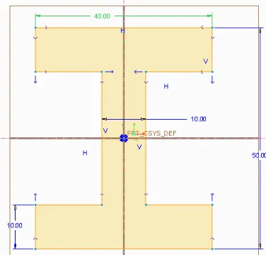
I Shape models have been fabricated for the present study and the material used is Acrylonitrile Butadiene Styrene (ABS) thermo-plastic. FDM principle based 3D printer is used to print the models of various part thicknesses in two different layer orientations (horizontal-vertical, criss-cross) with common layer thickness of 0.1mm for all the parts. The various dimensions of the I-Shaped prototype are shown in figure.2.The various part thicknesses considered in this study are of 3mm, 4mm, 5mm, 6mm. Hence a total of eight samples were fabricated. The table.I shows the details of no. of specimens fabricated for the respective orientations and part thickness.
The detailed breakups of the number of specimens fabricated for each layer orientation and part thickness is given in Table I.
TABLE. I: Orientation-Thickness combinations for the Prototype.
Layer Orientation
Part Thickness (mm)
Horizontal &Vertical (00/900)
Criss-Cross(+450/-450)
3mm 1 1
4mm 1 1
5mm 1 1
6mm 1 1
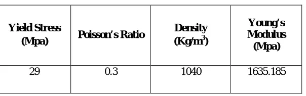
Mechanical properties of ABS material obtained in Tensile test are as follows:
TABLE IIMECHANICAL PROPERTIES OF ABS PLASTIC
Yield Stress
(Mpa) Poisson’s Ratio
Density (Kg/m3)
Young’s Modulus (Mpa)
29 0.3 1040 1635.185
III. EXPERIMENTAL SETUP AND EXPERIMENTATION
The fabricated models were set for analysing their natural frequency. The experimental system consists of three main components: 1. Impact Hammer, 2.Accelerometer, 3.Data Acquisition System(DAQ).
Figure3, Figure4&Figure5 shows the components employed for the present experimentation.
Figure4. Accelerometer
Figure5. DigitalAcquisition(DAQ)System
The Impact hammer is used to create an impact over the prototype. The accelerometer is used to convert the mechanical motion of the structure into an electrical signal. The DAQ system is used to convert the analog signals into digital format. Software, DEWESOFT 7.1.1. is used to execute signal processing and to analyse.
Free vibration is conducted on the test specimen to obtain its Dynamic characteristics includes natural frequencies and deflections. The prototype is supported as cantilever. The impact is applied by striking at the free end of the test specimen.
During free vibrations, the dynamic response of the beam is measured through the accelerometer. For this test, the location of the accelerometer is set at the free end of the prototype, inorder to extract the signals of the vibrations. The accelerometer mounted is used primarily for measuring the response in terms of acceleration. A Data Acquisition system is used to store the record data and transfer the measured data to the system installed PC for analysing the results. From this Fast Fourier Transform [FFT] graphs are obtained and hence the natural frequencies are analysed.
The prototype is supported as a cantilever and hammering is done at the free end by using the Impact Hammer and the Accelerometer which is attached to the prototype with the help of wax, record the vibrations and the recorded vibrational signals are sent to the Digital-To-Analog conversion unit. Then the analog signals are sent to analysis in DEWESOFT 7.1.1. Thus the vibrational analysis is done and the natural frequency values are obtained. Also the deflection in terms of ‘g’ value are obtained and equivalent values are calculated in terms of ‘mm’ using an empirical relation.
IV. EXPERIMENTAL RESULTS
For the experimental setup and the process of experimentation done, the natural frequencies obtained are noted as shown in table.III. Finite Element Analysis [FEA] is also done for the same prototypes to analyse their frequencies and deflections. The values obtained from FEA are also noted. Hence the experimental results and FEA results are compared and as shown in table.IV.
Also, the variation in frequencies is observed with the change in layer-orientation. For the layer orientation of Horizontal (00/900), the frequencies obtainedwere greater compared to criss-cross (+450/-450) orientation. This shows that the criss-cross layer oriented parts have greater stability.
From the comparison of the Experimental results & FE Analysis results, small variation in the results observed. This might be due to process-errors occurred/encountered during fabrication of prototypes.
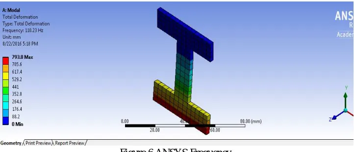
The Frequency graph as shown in Figure5 was obtained from ANSYS WORKBENCH 17.0 for I-shape model with 3mm thickness. The frequencies of the remaining specimens are driven out of ANSYS as the present one.
Figure 6 ANSYS Frequency
TABLE III FREQUENCY AND DEFLECTION
Part thickness
(mm)
Layer
Orientation Frequency(HZ) Deflection (mm)
3mm
Horizontal & Vertical (0/90)
140 0.00313
Crisscross (45/-45)
117.5 0.01041
4mm
Horizontal & Vertical (0/90)
152.5 0.000170
Crisscross (45/-45)
117.5 0.00381
5mm
Horizontal & Vertical (0/90)
172.5 0.00122
Crisscross (45/-45)
170 0.00387
6mm
Horizontal & Vertical (0/90)
237.5 0.00263
Crisscross (45/-45)
TABLEIV COMPARISION OF NATURAL FREQUENCY
Part
Thickness(mm) Layer Orientation
Natural Frequency (Hz)
Experimental ANSYS
3mm
Horizontal and Vertical (0/90)
140
110
Crisscross (+45/-45) 117.5
4mm
Horizontal and Vertical (0/90)
152.5
145
Crisscross (+45/-45) 117.5
5mm
Horizontal and Vertical (0/90)
172.5
164.97
Crisscross (+45/-45) 170
6mm
Horizontal and Vertical (0/90)
237.5
215.99
Crisscross (+45/-45) 237
V. CONCLUSIONS
The experimental modal analysis is done to find out the vibrational properties of 3D printed I-shapedprototype supported under cantilever conditions. The results obtained from the ANSYS analysis are matching with those obtained experimentally. The natural frequency of the prototype obtained from experimentation indicates that the value changes when the part thickness and layer orientation of the model changes. This indicates that catastrophic failures may occur if proper layer orientation and part thickness are not selected in real life situations. Further experiments are needed to verify the vibration properties of the Rapid Prototyped components.
REFERENCES
[1] V. Scott Gordon, James M. Bieman, “Reported effects of Rapid Prototyping on industrial software quality”; Software Quality, Journal, vol. 2, pp: 93-110, June
1993.
[2] DetlefKochan, Chua Chee Kai, Du Zhaohui, “ Rapid Prototyping issues in the 21st century”; Computers in Industry vol. 3, pp. 3-10, 1999.
[3] O. S. Es-Said, J. Foyos, R. Noorani, M. Mendelson and R. Marloth, “Effect of layer orientation on Mechanical properties of Rapid Prototyped samples”; Materials
and Manufacturing processes, Vol 15, No.1, pp. 107-122, 2000.
[4] Hopkinson, N. and Dickens, P.M.,” Rapid prototyping for direct manufacture. Rapid prototyping”; journal, 7 vol. 4, pp. 197- 202, 2001. DOI:
10.1108/EUM0000000005753.
[5] Sung-Hoon Ahn, Michael Montero, Dan Odell, Shad Roundy and Paul K. Wright, “Anisotropic material properties of fused deposition modeling ABS”; Rapid
prototyping Vol. 8- Number 4, pp. 248-257, 2004.
[6] Steve Upcraft, Richard Fletcher, “The Rapid Prototyping technologies”; Assembly Automation, Vol. 23, Number 4, pp. 318-330, 2003.
[7] Pham, D., &Dimov, S., Rapid prototyping: A time compression tool; Ingenia, vol. 17, pp. 43–48, 2003.
[8] Yucheng Ding, HongboLan, Jun Hong, Dianliang Wu, “An integrated manufacturing system for rapid tooling based on rapid prototyping”; Robotics and
Computer-Integrated Manufacturing vol. 20, pp. 281-288, 2004.
[9] B. Valentan, T. Brajlih, I. Drstvensek, J. Balic, “Evaluation of shape complexity based on STL data”; Journal of Achievements in Materials and Manufacturing
Engineering (JAMME) Vol. 17, Issue 1-2, pp. 293-296, 2006.
[10] A. Bagsik, V. Schoppner, E. Klemp,“FDM part quality manufactured with Ultem 9085”; 14th International Scientific Conference on Polymeric Materials,
vol.17,issue 8, 2010.
[11] NurSaaidah Abu Bakar, Mohd Rizal Alkahari, HambaliBoejang, “Analysis on Fused Deposition Modelling performance;” Journal of Zhejiang University-
SCIENCE A (Applied Physics & Engineering), vol. 12: pp. 972-977, 2010.