Numerical Prediction of Crack Propagation Behavior in Structural Component by
Enhanced Element-Free Galerkin Method
Sang-Ho Lee 1~, Young-Cheol Yoon 1~ and Jang-Ho Jay Kim 2)
1) Department of Civil Engineering, Yonsei University, 134 Shinchon-Dong, Seodaemoon-Ku, Seoul 120-749, Korea 2) Department of Civil Engineering, Sejong University, 98 Kunja-Dong, Kwangjin-Ku, Seoul 143-749, Korea
ABSTRACT
In this paper, an improved Element-Free Galerkin (EFG) method is proposed by adding enrichment function to the EFG approximation and discontinuity function to the shape function. The singularity and the discontinuity of the crack are efficiently modeled using the enrichment basis and the discontinuity function, respectively. It is a well-known fact that EFG method is one of the most suitable analysis methods for crack propagation problems because node distributions are not restricted by element connectivity. The proposed method improves an already powerful method by using only initial nodes arrangement without any additional modification until an analysis is completed.
Also this study proposes an unconventional approach in the analysis of fatigue crack growth which predicts the crack growth path and the fatigue life of the pre-cracked structural members. From these analysis results, an engineer is able to obtain crucial data needed to determine the capacity and safety of the structures for repairing and strengthening purposes.
INTRODUCTION
In realistic situations, cracks grow in arbitrary directions under mixed mode loading conditions. This consecutive crack propagation direction requires an analysis that must trace the crack for each crack growth step. Therefore, the general numerical computation analysis method such as FEM must remesh continuously to follow the crack growth path. The features such as a crack growth rate, a crack growth direction, and a repeated process treating specialized numerical techniques must be included in the computational method.
The Element-Free Galerkin (EFG) method, a mesh-free method, can be modified to analyze fatigue crack growth
problems. The EFG method was developed by Belytschko et al. [1] and has been applied to solving problems of solid
member with continuous changes in geometry due to static and dynamic fractures [2], [3], [4]. Since the essential
boundary condition of mesh-free method is difficult to satisfy, several methods such as Lagrange multiplier method, modified variational principle, or penalty method have been proposed to enforce essential boundary conditions [5]. In
addition, a method coupling with conventional FE [14] was also tried. Lately, an approach to solve the problem was
studied using a constrained variational principle with a penalty function by Gavete et al. [12] where a formulation for
penalty condition was derived by applying weak form for kinematic boundary condition, Galerkin method and point collocations, [13]. Also, some improvements in numerical integration of the Galerkin weak form in meshfree methods was investigated [9] and convergence of the continuous and discontinuous shape functions in the Element-free Galerkin method was studied. In the case of a linear shape function, the convergence rate was not affected by the discontinuities [15]. Organ
et aI. [18] studied a technique of smoothing EFG shape functions around the crack tip to improve the accuracy of the solutions and Belytschko and Fleming [6] proposed several methods to enrich the EFG approximations near the crack tip. With EFG method, an adaptive approach to a crack problem based on strain gradient was studied [13]. A formulation for stable crack growth in an elastic solid [23] and quasi-static growth concerning crack tip plasticity in elastic-plastic materials was similarly improved by Xu [24]. The EFG method having an expression for normalized, critical traction for quasi-static, mixed-mode fracture was presented [20].
Recently, based on FEM, a crack growth modeling technique with only minimal remeshing and enrichment function was developed by Belytschko and Black [7] and it can be noted that the formulation procedure is similar to that of enriched
EFG method [11]. Mo~s et al. [16] developed a FEM requiring no remeshing and being able to analyze crack growth,
which was called 'X-FEM'.
This paper will first briefly review the formulation procedures of EFG method and present an improvement for the crack modeling technique for EFG method. The singularity and the discontinuity of a crack are efficiently modeled using the enrichment basis and the discontinuity function, respectively. Subsequently, to improve the applicability of the developed method, a stress analysis technique using EFG method is combined with a generalized fatigue crack growth theory. Then, a numerical simulation method analyzing crack growth behaviors such as crack paths and growth rates is proposed. Finally, several numerical examples are presented.
EFG METHOD FOR CRACK MODELING USING ENRICHED FUNCTION AND DISCONTINUITY FUNCTION
Reviews of Moving Least Square Approximation
The Element-Free Galerkin method as formulated by Belytschko et al. [1] will be briefly explained for 2-D elasticity.
SMiRT 16, Washington DC, August 2001 Paper # 1519
In elastostatics problem, the EFG method has essential features of a system of equations and kinematic boundary conditions incorporated with Moving Least Square approximation and constitutive law for elasticity. In EFG method, an
approximation function u h ( x ) for a domain surrounding the target point x can be obtained by using the moving least
square (MLS) interpolant. The function u ( x ) is approximated by
t/N
u h ( x ) = ~ p i ( x ) q t ( x ) _ p r q (1)
I=1
where, u h ( x ) denotes the approximation of the function u ( x ) , P l ( X ) is a polynomial basis of arbitrary order, and
q i ( x ) is the corresponding unknown coefficient. In order to obtain the coefficient vector q ( x ) we can consider a
weighted residual and the stationary condition that minimizes the weighted residual. As a result we obtain the MLS approximation as
n N m rlN
h
(x)(A-1
u ( x ) - ~ p j ( x ) C ( x ) ) j l U I = ~ N i ( x ) d I = N d (2)
I j /=1
where m is the number of terms in the polynomial basis, the matrices A ( x ) and C ( x ) are given as equation (3a), (3b)
and the shape function N I (x) for node I in the local domain is defined as equation (3c).
n N
A ( x ) - ~, w ( x - x I ) p ( x I ) p r (x I ) (3a)
I=1
C ( x ) - [w(x - x I ) p ( x I ), ... , w ( x - Xnu )P(XnN )] (3b)
m
N I ( x ) = Y ' , p / ( x ) ( A < ( x ) C ( x ) ) / : . (3c)
J
The weight function is an essential part of MLS interpolation. The correct choice of the weight function improves the accuracy of the approximation. The weight function determines the relative weight of an arbitrary point contained in the domain of influence of a node. As the distance from the node increases, the weight will decrease and vise versa. Additionally, the value of weight will be zero when a node lies outside of the domain of influence. In the EFG method, various weight functions can be used with a compact support type [5]. The weight function with Gaussian form is applied in this study. It is important to determine the proper size of the local domain. The size is associated with the number of points included in constructing a shape function of the node by MLS interpolation. In this study, a circular type of local compact support that can change its size according to the density of neighboring nodes is used and the neighbor nodes of proper number will be included in the local domain to construct stable shape functions.
P r o b l e m F o r m u l a t i o n
A 2-dimensional problem with a linear elastic constitutive law and small displacements on the domain g2 bounded by F ( F - F, w F t vo F C ) is considered. Here, Fc+ and F c_ indicate crack surfaces with traction free condition. In each
point x 6 g2, the differential form of the governing equations yields equation (4a) with stresses a and body forces b and boundary conditions to be satisfied are also given in (4b) and (4c).
V . o" + b = 0 in g2 (4a)
o'. n = / on F t (4b)
~ . n = 0 on Fc+ a n d F c_ (4c)
where, the superposed bar denotes prescribed boundary values, n is the unit normal to the domain g2, and t is the traction along the boundary.
Among the space of kinematically admissible displacement fields, the space of displacement trial function, test function, and H 1 space are shown in equation (5a), (5b), and (5c), correspondingly.
{
-
}
aU : { ~u e H ' ( a ) . du = 0 on F u , du is discontinuous on F c }
Hi(g2) = { u e Lz(E2)" V u ~ L2(g2) } where, L2(E2)= {u~ C ° ' ~ a u d g 2 < ¢ ~ }
(5b)
(5c)
The problem is to find u e U satisfying the governing equation. After considering the constitutive relation and the kinematics constraints, the weak form for the global system equation is taken as equation (6) with trial function from above space.
fa & r (6u) " D " e(u) dg2 - Ia 6u r . b d g2 + Iv, 6ur . { d P V & e 6U
(6)
where, 6'u is a test function in the same space of u of H ~ space.
However, it is a well known fact that essential boundary condition is not satisfied in the EFG method for the shape function of the EFG method since the Kronecker delta condition at each node is not satisfied. Though several methods are available in the weak form [5], [14], a penalty method is used to remedy this problem [2]. Though the larger value of penalty parameter results in a more accurate approximation, the choice is usually based on the experience of the analyst.
Discontinuity function
The discontinuity across crack faces is an inherent geometrical characteristic of a crack. When the domain is completely divided by a crack, there is no influence across the domain. To describe this discontinuity of crack surface,
Mo~s et al. [16] introduced a 'jump' function defined in the local crack coordinate system into the FE approximation.
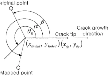
In this section, a new discontinuous function is implemented in EFG approximation. In order to exclude the neighboring nodes located at the opposite side of the crack from the target node, new discontinuity functions were defined. Figure l illustrates some characteristic angles for defining sign functions and discontinuity functions. When analyzing the model, the crack is expressed as a series of straight-line segments. As the crack grows, a new crack segment is added to the previous model. In this procedure the discontinuity was aligned by a sequence of mappings. The mapping is achieved by rotating each section of the discontinuity onto the crack trace [7], [11], which is very useful in calculating fracture parameters for curved crack. Some angle descriptions in the mapping procedure were applied to newly define the sign functions as equation (7).
original point
Crack growth Crack tip direction
~//' (Xkinked'Ykinked)(Xt;'Ytip)
0
Mapped point
Figure 1 Some characteristic angles for the definition of the sign and the discontinuity functions
A discontinuity function is formulated by using the product of the two sign functions. As shown in equation (7), the sign functions have only the value of 1 o r - 1 for the conditions of the angle ratio.
G ( O ) = I 1 f o r c~/O R >_I and H ( O ) = I 1 f o r f l / O R >_I
l - 1 f o r a ' / 0 R < l
L-I
f o r / 5 ' / 0 R < l(7)
The discontinuity function is shown as equation (8), which is a criterion of excluding the node that has no influence on the shape function of the target node due to the presence of a crack.
S(O)=G(O) H(O)
(8)where, if S(O) is equal to 1, then x m e I disnbr and i f - 1 , then x m ~ I disnbr . In other words, when the discontinuity
[ disnbr indicates the neighbor nodes that should be included in MLS approximation. The set is as follows
I disnbr : { X m E
N'diat(xs,
x)<
d / m a x , S(O)=1 }
(9)where, N refers to the set of all nodes in the model and dist(x I , x ) , the distance between the target node and the neighbor
node of interest.
EFG Method with Enriched Functions for Crack
The model consists of the EFG method and a crack representation which utilizes an approximation with enriched basis and discontinuity function. In this section, an enrichment approximation is implemented in the conventional EFG
approximation for the case where the domain is partially divided by the crack. Earlier Moes et al. [16] developed a
standard finite element model with discontinuous enrichment. This research partially shares the main idea of the former approach. The conventional EFG approximation does not contain certain terms to express the singularity near crack tip as shown in equation (2). But a new approximation includes the enrichment terms for describing the singularity near crack tip and can be written as
n N n E 4
u h ( x ) = Z N s d i + ~, ~ - ' N s g k ( x ) a l k = N d + N g a (10)
I=1 I=lk=l
where, N I is the EFG shape function, n g is the number of neighboring nodes and n E is the number of nodes using
enriched function. It is notable that the number of interpolating basis nodes in the first and the second term is not same as
the bar above the matrix form denotes. Additionally, g k ( x ) indicates the standard enrichment functions expressed as
equation (11).
O ~/Tsin o ~ r sin O sin O, ,j-r-r cos 0__ sin 0}
gk (x) - .4'7r cos-~-, ~-, 2 2 (11)
In order to obtain the system equation, the strain-displacement approximation is initially taken as follow:
n N n E 4
6 h (X) = Z NI.iUl + Z ~_.[Nl.igk (X)+ N I gk.i(X)] alk =
Bd + (Bg + Nh)a
I=1 I=1k=1
(12)
where, B and h indicate the derivatives of shape function N and enrichment function g , respectively. Then, equation (11) and (12) is substituted into weak formulation equation (6). The left hand side and right side of equation (6) turn into equation (13a) and (13b) respectively.
LHS o f (6) - ~a 6er (&)" D ' e ( u ) dg2
q- ¢~lT Ig2 [( gkT -BIT q- hkT "NIT ) D B j d + (gk T B--IT+ hk T N t T )D(-Bj gl + N j h l ) a ]d~~
(l?a)
RHS of
( 6 ) -
.Tar, +
.Oda
_ , +
(13b)
Arranging above equations with respect to N/r and ~ r , the discrete system equation as equation (14a) is
obtained in matrix form and each component of the system equation is shown as the detailed form in equation (14b) to (14f). Note that the coefficient matrix in the system equation remains symmetric and positive definite.
E""
{ I' }
K m r K ~g~l a f zk
Ktj = IaBITDBj dg2
K I j ` = ~ a B l r D ( - B j g l + N , h l ) d g 2 , l = 1, ..., 4
KiJk, -,a(gkrB--i T +hkTNzr)D(-Bjg, +Njh,)dg2, k , l - 1 , . . . , 4
f , : y c N z r t d F + y a N z r b d f2
T - - - r ~ t r b _ ,
f Zk - ~r gk N zr t dF +fagk dg2, k 1,... 4
(14b)
(14c)
(14d)
(14e)
(14f)
In the EFG method, modeling of the discontinuity across the crack faces and the singularity at the tip can be calculated using nodes and geometric information. As a crack grows in an arbitrary path, a numerical modeling must be able to trace the path. When the crack tip lies in the domain of influence, the influence between the nodes in the domain must be considered to a certain degree. In order to guarantee accuracy and continuity, the approximation function should be modified properly. In this study, the diffraction method [6] is used where the distance between the nodes is corrected. The correction is required for the extraction of the shape function near the surface or the tip of crack. This method enables the reflection of the effect of nodes placed on each side of the crack line.
If the plastic zone in front of the growing fatigue crack can be assumed to be small, a crack analysis can be done based on LEFM. In order to calculate a SIF for a specific geometry and a loading condition, the domain integral form (the
interaction integral or M-integral) [17] is used, which is developed from the domain form of J-integral. Although this
interaction integral is an effective tool for calculating mixed mode SIF, it should be noted that the method is only applicable to elastic problems.
ESTIMATION OF THE REMAINING FATIGUE LIFE
Calculation of Crack Growth Direction
Two noteworthy elements on a fatigue crack analysis are the crack growth direction and rate. The calculation of the direction of crack extension is considered in advance. The maximum principal stress criterion (MTS criterion) [10] is used. In the theorem, a crack is assumed to grow in a direction perpendicular to the maximum hoop stress. From a relationship
between the crack growth direction 0 m and stress expressions by Westergaard and MTS criterion, the Stress Intensity
Factor (SIF) ranges is obtained as
AKI sin 0 m + AKI~ (3 cos 0 m - 1) = 0. (15)
Since fatigue laws are generally based on an equivalent mode I case to simulate actual mixed mode behavior, the
following equation for AKeq is used [8]
(tanS)
1 K~ + 1/4l( / 2
KI -1- 8 .4 K , , - ~ , K u ) (16)
Equation (16) gives closed form solution for the crack growth direction without any iteration by means of equating the trigonometrical function given by equation (15).
Prediction of remaining fatigue life of crack
It is crucial for engineers to predict whether the structural component is safe during its design life. In this section, the fatigue growth rate is considered as the other noteworthy element of predicting fatigue crack behavior. Paris [19] proposed an empirical description of the fatigue crack growth rate as a function of a fracture parameter and is shown as
da
dN - C(AKeq )m (17)
where, the equivalent SIF range AKeq is related to the crack geometry and the applied load, and constants C and m
provides a single measure of the mixed mode stress field.
An equivalent SIF range as a representative parameter in the crack growth model can be obtained through various
ways [22], [25]. However, by plugging the growth angle 0 m into the tangential stress of Westergaard stress fields, we
calculated SIF range as
0 m 0 m
AK eq = AK i cos 3 -- 3AK ii cos 2 0 m sin ~ . (18)
2 2 2
It should be noted that the effects of the small (or short) crack, stress ratio, variable loading, and retardation of crack are not included in this model. Only a constant amplitude load as a special case with zero minimum load is considered.
For the application of damage tolerance concepts, it is necessary to make a reliable estimate of the number of load cycles required to propagate the crack from the initial state to the failure. The end of life is related to the time which (1) a specified value of crack length or cycles is reached or (2) a failure criterion is reached. Furthermore, when defining inspection intervals, the following conditions must be considered: (1) Initial crack size is based on the largest crack that might be missed by Non-Destructive Test; (2) Inspection interval may correspond to a specific probability of detection; (3) Final crack size is based on the limiting crack for fracture with a noteworthy safety factor.
The fatigue crack propagation analysis in this study is performed by repeated stepwise procedures from i to rz steps
based on a maximum allowable crack increment A a l n a x . The detailed explanation of the procedure is as follow. The
process initiates by computing the stress fields for a given crack geometry and boundary conditions using EFG method. Then, the SIFs, the equivalent mode I SIF ranges, and the crack growth angle are evaluated. Using the crack growth
integration, a fatigue cycle AN~ inducing the maximum allowable crack increment Aalnax is computed for the fastest
growing crack. After this fatigue loading cycle is applied to the entire model, the increment of each crack corresponding to the cycle is determined. Therefore, the total length of each crack is calculated from the following equation.
atota 1 = ~~ Aa i = ~-" c(Ageqi )mz~¥ (19)
i=1 i=1
Then, a new description for modified geometry is determined for the next stress analysis step by rearranging EFG nodal distributions. During these repeated procedures, the fatigue life curve is obtained by accumulating the increment of crack at every step using the following equation and also the remaining fatigue life of each crack is calculated.
_~-, Aai Ntotal-~"~l~i- )m
i=1 i=1 C(AK eq i
(20)
In the procedures mentioned previously, it is important to note that an analyst has to pay a special attention to the choice of a maximum allowable crack increment, because the chosen magnitude of a maximum allowable crack increment has a great effect on the computational time and the accuracy of fatigue life of crack.
NUMERICAL EXAMPLES
In this section, a benchmark problem is simulated to verify the accuracy of the developed method. An edge-cracked
specimen under uniform tension ( Cry = 1 psi ) is simulated. The problem was solved for the plane stress case with Young's
modulus E = 3 x l 0 6 psi (42.6x10⁶ kg/cm a) and Poisson's ratio v = 0 . 3 where a linear basis function and a standard
enrichment function were used. In Figure 2(a) the weight function of an exponential form and its derivative is illustrated. The weight function should have the fairly compact form, because the solution near the crack tip field sharply changes due to the singularity of the crack tip. The shape function strictly follows the shape of the weight function. If the shape function and its derivative do not have a sufficient compactness, the crack tip singularity cannot be appropriately approximated.
Figure 2(b) shows the node distribution used in analysis and y-directional stress contour plot at the state of a = 3.5 in.
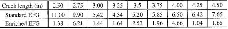
Consequently, in spite of choosing a regular and coarse node distribution, the resultant stress field successfully locates the near tip field which is difficult to obtain by using only the standard EFG approximation. The stress intensity factor(SIF) evaluated by the enhanced EFG method is shown in Figure 2(c) and the accuracy of the numerical solution was illustrated through the comparison with the standard EFG method and the analytic solution by Tada [21]. The standard EFG crack analysis yields slightly lower values than the analytic solution but the proposed method shows good agreement with it. The relative errors in SIF for the crack lengths are given in Table 1. The proposed method decreases the errors in SIF calculation by capturing the sharp stress field near crack tip. As the crack grows in mode I state, the initial node distribution requires no modification until the computation is completed. This feature is improved aspect to the standard EFG method which demands partial node redistribution following a crack growth.
as shown in Figure (2c). From numerical examination, it was revealed that more enriched nodes do not lead to better solution and too many enriched nodes even deteriorate the accuracy of the solution. Since additional neighboring nodes severely increase the size of the global system of equations to be solved, taking only four or a little more enrichment nodes is recommended to capture the sharp stresses around the crack tip. This simplicity allows the enhanced EFG method to reduce numerical computation time compared to that of the standard EFG method. Moreover, this approach is simpler than
previous enriched EFG method by Fleming et al. [11] or Belytschko and Fleming [6] where the whole domain of the
model should be enriched and the formulation is quite complex.
1.5 dmax=2.5 / alpha= 0.26
,, ~ Weightft
t" \
Derivative of weight ftI ... ! " -
~ ,,
I I
i/
-1
-15__ I ' I ' I ' 1 ' I '
-2 -1 0 1 2
Distance from a sampling point
16.00 ... ~ ... ~ ... :~ ... g ... ~ ... ~ ... :!i!:~::iiiiii~.i iilil iiili i~Eiiiiii!iiiiiiiiii~iiiiiiiiii!iiiiiiiiiiiiiiiiiii!iiiiiiiiiiiililil i~i ili iiiiiii ii!iiiii!!:iiii!!iiii:~iiiill i:i::i i:i}::i:ii: i~.i ~:!ii~ji!ii~i!:il
,4.o ! ! ii i: 11
,~.o~ ',! i i :.: i Ii',~:::i~=i=.:=',i'=i :. :=: ~i~ii!~=~i~ii~J~:i}!i~:!i~i~!~!~E~£!iii!£i~i!i~iiii~Uiiii '~ ~o.o~
~00
: ii~!lil
o.oo:: ' : ~ ~iii~"
40' • ii ~ i ~ ;-ii
OOli{!!il
0.00 2.00 4.00 6.00(a) (b)
14.00 30 -
13.00
12.00 25
11.00 L _
o 10.00 -,~
9.00 ~ 20
8.00 >,,
7.00 ¢n
~" 15
6.00 •
c- 5.00
4.00 ~ 10
(D 3.00 .,i.-., =" O3 2.00
1.00 5
0.00 -1.00
0 -2.00
-3.00
• Standard EFG (w/o enrichment) / Enriched EFG (This s t u d y ) i o ... Analytic Solution
l
0 1 2 3 4 5
Crack length
(c)
Figure 2 (a) Weight function and its derivative (b) node distribution and stress ( Cry ) contour plot (c) Stress intensity factor
Table 1 Relative error in stress intensity factor for the crack lengths (%)
Cracklength(in) II 2. 0 1275 I .00 1 .25 I
14.00 14.25 [4.50
Standard EFG 11.00 9.90 5.42 4.34 5.20 5.85 6.50 6.42 7.65
Enriched EFG 1.38 6.21 1.44 1.64 2.53 1.96 4.66 1.04 1.65
CONCLUSIONS
In this study, an enhanced EFG method was proposed by adding enrichment and discontinuity function to the conventional EFG formulation and was implemented to a mode I crack growth problem for the verification of the developed algorithm. The main conclusions derived in this study are as follow.
1) In the enhanced EFG method, adding the enrichment function to the approximation enables the approximation to capture the sharp stress field near the crack tip. Also, the developed discontinuity function was successfully implemented in constructing the shape function for the description of a crack surface discontinuity.
2) Numerical example showed that the stress intensity factor could be accurately evaluated and the growing crack can be followed without any additional modification of the initial node distribution until the end of the analysis.
3) When the enriched approximation is applied, the choice of the weight function is very important factor on the accuracy of the solution. Numerical investigations revealed that the weight function with considerable compact form gives better solution than other ones with the smooth form.
4) Only few enriched nodes are required to guarantee the capturing of the sharp stress field near the crack tip and reduce computational time required in computing the enrichment.
5) The proposed method could be used as a tool to evaluate serviceability of steel structures with cracks and to analyze complicated crack propagation problems in which theoretical or empirical analysis is difficult.
A C K N O W L E D G M E N T
REFERENCES
°
9.
10.
11.
12.
13.
14.
15.
16.
17.
18.
19.
20.
21. 22.
23.
24.
25.
Belytschko, T., Lu, Y. Y. and Gu, L., "Element-free Galerkin methods," International Journal of Numerical Methods in Engineering, vol.37, 1994, pp.229-256.
Belytschko, T. and Gu, L., Lu, Y. Y., "Fracture and crack growth by element-free Galerkin methods," Modeling Simulations in Materials Science and Engineering, vol.2, 1994, pp.519-534.
Belytschko, T., Lu, Y. Y., Gu, L. and Tabbara, M., "Element-free Galerkin methods for static and dynamic fracture," International Journal of Solids and Structures, vol.32, 1995, pp.2547-2570.
Belytschko, T. and Tabbara, M., "Dynamic fracture using element-free Galerkin Methods," International Journal of Numerical Methods in Engineering, vol.39, 1996, pp.923-938.
Belytschko, t., Krongauz, D., Organ, M., Fleming, M. and Krysl, P., "An overview and recent developments," Computer Methods in Applied Mechanics and Engineering, vo1.139, 1996, pp.3-47.
Belytschko, t. and Fleming, M., "Smoothing, enrichment and contact in the element-free Galerkin method," Computer and Structures, vol.71, 1999, pp.173-195.
Belytschko, T. and Black, T., "Elastic crack growth in finite elements with minimal remeshing," International Journal for Numerical Methods in Engineering, vol.45, 1999, pp.601-620.
Broek, D., "Elementary engineering fracture mechanics," Martins Nijhoff Publishers, 1986, 4th Ed.
Dolbow, J. and Belytschko, T., "Numerical integration of the Galerkin weak form in meshfree methods," Computational Mechanics, vol.23, 1999, pp.219-230.
Erdogen, F. and Shi, G. C., "On the crack extension in plates under loading and transverse shear," Journal of Basic Engineering, vol.85, 1963, pp.519-527.
Fleming, M., Chu, Y. A., Moran, B. and Belytschko, T., "Enrichment Element-Free Galerkin methods for crack tip fields," International Journal for Numerical Methods in Engineering, vol.40, 1997, pp.1483-1504.
Gavete, L., Benito, J. J., Falc6n, S., and Ruiz, A., "Implementation of essential boundary conditions in a meshless method," Communications in Numerical Methods in Engineering, vol. 16, 2000, pp.409-421.
H~iussler-Combe, U. and Korn, C., "An adaptive approach with the Element-Free Galerkin method," Computer Methods in Applied Mechanics and Engineering, vo1.162, 1998, pp.203-222.
Krongauz, Y. and Belytschko, T., "Enforcement of essential boundary conditions in Meshless approximation using finite elements," Computer Methods in Applied Mechanics and Engineering, vo1.131, 1996, pp.133-145.
Krysl, P. and Belytschko, T., "Element-free Galerkin method: Convergence of the continuous and discontinuous shape functions," Computer Methods in Applied Mechanics and Engineering, vo1.148, 1997, pp.257-277.
Mo~s, N., Dolbow, J. and Belytschko, T., "A finite element method for crack growth without remeshing," International Journal for Numerical Methods in Engineering, vol.46, 1999, pp.131-150.
Moran, B. and Shih C. F., "Crack tip and associated domain integrals from momentum and energy balance" Engineering Fracture Mechanics, vol.27, 1987, pp.615-641.
Organ, D., Fleming, M., Terry, T. and Belytschko, T., "Continuous meshless approximations for nonconvex bodies by diffraction and transparency," Computational Mechanics, vol.18, 1996, pp.225-235.
Paris, P. C. and Erdogan, F., "A critical analysis of crack propagation laws," Trans. ASME, Journal of Basic Engineering, D85, 1963, pp.528-534.
Tabbara, M. R. and Stone, C. M., "A computational method for quasi-static fracture," Computational Mechanics, vol.22, 1998, pp.203-210.
Tada, H., Paris, P.C. and Irwin, G. R., "The stress analysis of cracks handbook", Del Research Corporation, 1973. Tanaka, K., "Fatigue crack propagation from a crack inclined to the cyclic tensile axis," Engineering Fracture Mechanics, vol.6, 1974, pp.493-507.
Xu, Y. and Saigal, S., "An element free Galerkin formulation for stable crack growth in an elastic solid," Computer Methods in Applied Mechanics and Engineering, vo1.154, 1998, pp.331-343.
Xu, Y. and Saigal, S., "Element free Galerkin study of steady quasi-static crack growth in plane strain tension in elastic-plastic materials," Computational Mechanics, vol.22, 1998, pp.255-265.