ISSN:2574 -1241
The Applied Artificial Intelligence to the Control
Electronics Improving the Energy Efficiency of
Ventilation Systems in the Industry
Enrique Santana López
1, Deynier Montero Góngora*
2, Orlando Vega Arias
3and Imandra Rojas Díaz
1 1University of Camagüey, Camagüey, Cuba2University of Moa “DrC Antonio Núñez Jiménez”, Cuba
3Nickel and Cobalt Production Company “Comandante Ernesto Che Guevara”, Cuba
*Corresponding author: Deynier Montero Góngora, University of Moa “Dr C Antonio Núñez Jiménez”, Avenida Calixto García
Iñiguez No. 15 between Avenida 7 de December and Calle Reynaldo Laffita Rueda, Reparto Caribe, Moa, Holguín, Cuba
DOI:10.26717/BJSTR.2020.25.004273
Received: February13, 2020 Published: February 24, 2020
Citation: Enrique Santana López, Deynier
Montero Góngora, Orlando Vega Arias,
Imandra Rojas Díaz. The Applied Artificial
Intelligence to the Control Electronics
Improving the Energy Efficiency of
Ventilation Systems in the Industry. Biomed J Sci & Tech Res 25(5)-2020. BJSTR. MS.ID.004273.
Keywords: Artificial Neural Networks; Multi-Household Furnace; Combustion Air Supply
ARTICLE INFO Abstract
In the furnaces of multiple hearths there is a problem related to the inefficiency of the current control of the combustion air system and the energy reserves present, since manually the excess air flow is regulated, while the fans work at full capacity all the time what produces an unnecessary expenditure of electrical energy. The experimental identification of the air supply system through artificial neural networks and fuzzy logic is executed for the future implementation of a control architecture with a view to increasing the energy efficiency of said process. Several experiments were carried out: first, in a laboratory, on an air flow test bench simulating in miniature the real process with a possible closed loop that links the input variables (sensors) with the speed of the motor (actuator: speed variator) ) and second, field, on one of the actual slabs of the plant, varying the number of revolutions of the motors in a staggered way around an operating point, alternating the operation of the fans with manual adjustment of the variable speed drives that they were installed previously. Of all the configurations tested, the most energy efficient variant resulted in the use of the two fans farthest from the common manifold (seven and eight), keeping the reserve nine. The proposed artificial neural model predicts the air pressure in the collector with 98 % correlation and 71 %
in its generalization.
Introduction
The Mining and Metallurgical Industry has become one of the
bases on which the economic-industrial development of the country
is based and is one of those that currently faces the challenge of
Business Improvement, a way to achieve a global competitive level. This business improvement as an integral process cannot ignore the technological improvement from a consistent application of the advances of science and technology. In nickeliferous plants in which
carbonate-ammonia leaching technology is used, also universally
known as the “Caron” process, multiple soleno kilns are used in the process of reducing the ore, which represent an important link in the chain. The present work was carried out in one of these plants, specifically in the combustion air supply system in the Reduction Furnaces plant of the Commander Ernesto Che Guevara de Moa.
The plant has a total of nine fans driven by 220 kW motors, six of them remain permanently in operation and in previous work it has been shown that there are reserves in the consumption of electrical energy that exceed 15%.
(diffuse logic, neural networks, neuro-adaptive networks or the combination between them), is a step forward for all industrial systems and processes. The techniques developed in the field of artificial intelligence are numerous and ubiquitous in processes of automation of systems and electrical drives, imposing themselves, due to their versatility, high precision and level of accuracy, with
great boom over traditional methods. Diffuse logic emerged, as a
generalization of classical logic, by the desire to represent reality
more faithfully.
Diffuse logic is used when the complexity of the process in question is very high and there are no precise mathematical models, for highly nonlinear processes and when definitions and knowledge not strictly defined (imprecise or subjective) are involved. As a main advantage, it should be noted that: offers exits in a fast and precise
way, thus reducing the transitions of fundamental states and the
ability to anticipate events over time, always stabilizing the physical environment it controls. It has been shown that neural networks can be used effectively and accurately for the identification and control of systems with complex dynamics, especially for non-linear plants that vary over time and are more difficult to regulate with conventional methods [4]. In particular, feed forward neural networks have been the most widely used for these purposes. The growing interest in neural networks is due to their great versatility and the continuous advancement in network training algorithms
and hardware [5].
Research Problem
There is inefficiency in the use of electrical energy associated with the motors that are coupled to the fans that supply the air to the industrial process and in many of them the demands are variable and difficult to predict, complicating the use of traditional
control methods.
Objective
Evaluate several alternatives using Microcontrollers, at the
Laboratory level, to propose a control strategy using Fuzzy Logic and the experimental identification of the air supply system through the use of artificial neural networks ¨feedforward¨, for the future implementation of a control architecture in this case, the study of a real industrial process with a view to increasing its energy efficiency. The MATLAB program was used as software to
carry out the investigation.
Development
Case Study
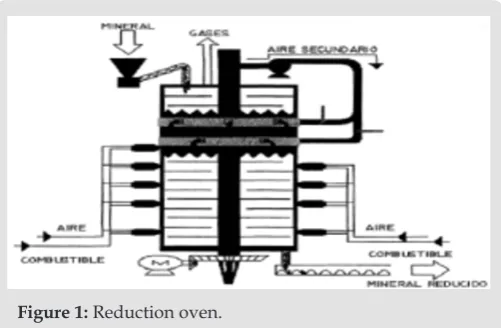
The Reduction Process: Herreshoff type furnaces [6], are composed of a metal cylinder lined internally with refractory bricks, protected externally by a metal housing, facilities for agitation,
feeding and unloading of the ore and combustion chambers. They
are formed internally by 17 homes or hearths that are shaped like spherical vaults. They also have a central rotating shaft to which 68
arms are articulated, four for each hearth Place (Figure 1). After the
ore is heavy, it is discharged to the feeder auger which transports the ore to the zero home at the top of the Furnace, being held inside for approximately 45 minutes. The reduction process is eminently
endothermic. For this reason the furnace has 10 combustion chambers arranged in homes 15, 12, 10, eight and six with high
pressure oil burners, which are responsible for producing hot
gases for heating the ore, at the same time that enrich the reducing
atmosphere of the furnace Place since they work with incomplete
combustion. Thus, it is necessary that the mineral in its descent is
subjected to an ascending temperature profile that allows a gradual heating, while penetrating a gaseous profile that guarantees an
increase in the concentration of reducers. The chemical reagent in
the process is the mixture of carbon monoxide and hydrogen, so
that the concentration of these gases in contact with minerals, at the
beginning of decomposition is extremely important. After reducing the nickel oxide and the higher iron oxides to metallic nickel and metallic iron respectively, the mineral mixture is discharged from
the furnace to a rotary conveyor.
Figure 1: Reduction oven.
Description of the Combustion Air System: In the “Reduction
Furnaces” plant there are nine three-phase delta connection
induction motors, of which three are reserve. These motors are
working in an underloaded regime, which have a high starting torque and after the current is restored they do not operate at their nominal power, the motors are connected by four belts to their centrifugal forced draft (suction) fan, which represent the
mechanical load for the asynchronous machine. The fans generate
an air flow that is supplied to the combustion chambers (PRIOR),
which mix the oil and the air, then go to the furnace Place. Each
furnace Place needs at least six chambers for the process to be carried out [7]. In the plant a slab is the structure of three motor-fan drives, with a reserve and the pipe network that corresponds to the link with the eight furnaces with their relevant chambers (Figure 2). Obtaining a mathematical model that describes the process from the phenomenological point of view would be extremely complicated, since the physical-chemical processes involved would lead to systems of differential equations in partial, nonlinear and time-derived derivatives. Therefore, the experimental identification
Figure 2: Composition of a slab of the furnace plant.
Implementation Phase of Artificial Intelligence for
the Control of Air Flow in the Bank Using the Arduino
Microcontroller
After conducting a broad search on the state of the art,
construction history of air flow test benches, suitable for electrical
engineers, background on Artificial Intelligence applied to Control Electronics to improve energy efficiency in Industrial Ventilation and with information and available resources, in the development
of this section, the tests that can be carried out on the ventilator are
stated, in a particular case study, so that the equipment available to them can be used to the maximum, and propose a control strategy using Artificial Intelligence in a case study of an industrial process with a view to increasing its energy efficiency. The project
also included the design and construction of several devices, the selection of the Microcontroller and the most suitable measuring
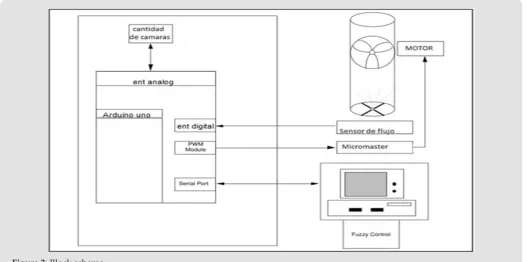
instruments to facilitate the execution of the planned experiments and to evaluate in a practical way the efficiency in the use of the electrical energy associated with industrial processes that use air as one of the main components. Figure 3 shows the block diagram of the control system which has an analog input to indicate the number of cameras in operation at the beginning of the process, a digital input with which the flow value passing through the sensor is measured the pipe.
Figure 3: Block scheme.
These values are sent to the PC where the intelligent algorithm is
carried out in Matlab. The intelligent algorithm will be implemented with four input variables, the two received by the Arduino and two
included by the PC, the value of the last maintenance and the air
pressure at the outlet of the duct obtained by calculation. After finishing the artificial analysis, the motor speed value is returned to the Arduino through serial communication. With this value we perform a conversion and obtain through the Arduino PWM a
modulated signal that we will use to send it to the frequency inverter
(MICROMASTER) that will act on the motor. Using the previously indicated elements, the test bench and its accessories were adapted. The study included the selection of the most appropriate measuring
instruments to facilitate the performance of the experiments. For the extension of the bank, based on the available fan that was used, a wind tunnel was built parallel to the existing one, whose structure and exterior appearance, already finished, is offered in (Figures 4 &
5). To simulate the loading conditions or in other words control the
air flow that leaves the fan, at a standard rotor rotation speed, they
were used initially, the one shown in Figure 4, in the case of a camera
sensor for which position sensors were used that indicate the limit
switch for holes drilled in the grooves as shown in the scheme and
Figure 4: Proposed installation scheme to expand the air tunnel in the fluid transport laboratory.
Figure 5: Photo of the bank enlarged and assembled with all the accessories of the experiment.
Through these position sensors, indicating open or closed chamber, and an open chamber counter, the air tunnel loads are varied, thus simulating an industrial process of digitally controlled induced air firing for five furnace-type chambers. In this case a potentiometer is used which will indicate to the program the number of open chambers in the process, the air tunnel loads are varied to be able to compare the values obtained with the research work previously carried out. Artificial Intelligence was implemented
with Matlab software, which receives the necessary data from the
Arduino board; air flow, pressure, operating time and number of cameras working. The air flow is measured directly with a sensor placed at the outlet of the ventilation duct (digital variable), the air pressure is measured in a practical way by the calculation route, the operating time is calculated by synchronizing the PC With programming, the number of cameras working in the process is an analog input which is simulated with a potentiometer. These values
are sent by serial communication to the Matlab and are stored in
the Workspace, from this step the declaration of the variables in
the blurred logic begins until obtaining the most optimal signal and being returned to the Arduino, which is sent by PWM This 0V-5V
signal and the drive for control need 0V-10V (Figures 6 & 7).
Figure 7: Flow sensor at the end of the tunnel to measure total flow.
To solve this problem, a circuit was built with an operational gain amplifier 2 to adapt this signal. This cycle is repeated by
refreshing all the readings. The two motors must be controlled in
parallel at the same time by a previous programming of the drive
to be able to establish real values of what had been assembled for the teaching of future mechanical engineers and thus establish the
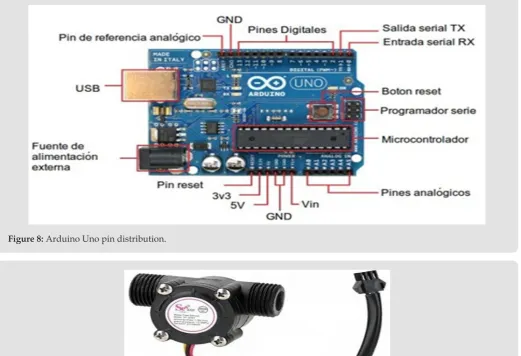
efficiency of placing electrical sensors for an energy control, the variator was programmed for the established load (two motors in parallel), the flow sensor was placed, to control and operate the system from the computer using the Arduino-1.8.5-Windows and Matlab Software and thus obtain a closed loop in this process. This air tunnel with electrical sensors is coupled with another air tunnel with mechanical sensors to be able to perform a measurement scale in the form of a comparison table with the actual values of the flow sensor in addition to the calibration of the electrical sensors. A summary of the main peripherals and auxiliary resources, the Arduino Microcontroller, including the distribution of pins, are shown in (Figures 8-11). Details are in the consulted bibliography.
Figure 8: Arduino Uno pin distribution.
Figure 10: Frequency inverter (CFW-08).
Figure 11: Rotary potentiometer.
Evaluation of Laboratory Experiments
All results were obtained:
1. Assuming that the last maintenance was at 9 months, fulfilling the maintenance technology cycle in order to compare these with those obtained in previous experiments.
2. T≥ 9 months = X (violation of the maintenance cycle)
(Table 1).
Table 1: Power requirement response in variant 1.
Tickets Exit
Microcontroller used Cameras
FLOW 3 m
h PRESSURE ( )pa SPEED (rpm)
3
406 103 870 PIC
406 103 877 Arduino
1000 315 855 Arduino
4
406 103 992 PIC
406 103 950 Arduino
1000 315 886 Arduino
5
406 103 1140 PIC
406 103 1100 Arduino
1000 315 889 Arduino
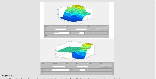
In accordance with these results, the surface graph of the fuzzy logic in Matlab of the output parameter (speed) that establishes the power requirement depending on the behavior of the input
variables is shown in Figure 12. Reference [2] shows in detail the variables declared in fuzzy logic, as well as the rules conditioned
in the process. In both variants, 75 to 85% of energy savings are obtained, at the laboratory level, which corresponds to the savings that would be obtained on an industrial scale, according to the field experiments carried out in Slab 3 of the Plant, manually manipulat
-ing the drives installed there, as shown in section 2.4 of this report.
Figure 12:
Field Experimentation in One of the Slabs of a Nickel
Industry Reduction Plant
In the investigated process, the motor speeds manipulated by three variable speed drives were taken as input variables, which
actuate the centrifugal fans seven, eight and nine of the slabs
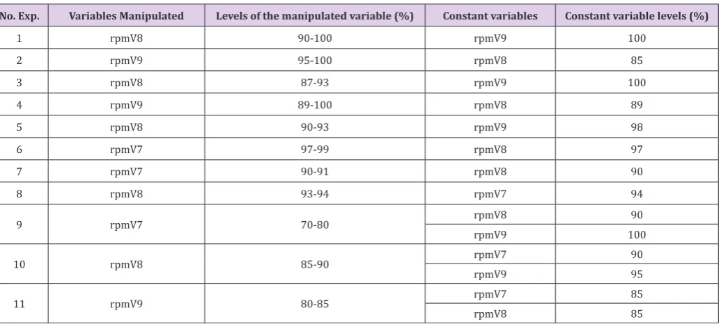
three and as an output variable the air pressure in the manifold. Several experiments were carried out (Table 2), alternating the operation of the fans similar to that embodied in [3] and positive and negative steps at different operating points were applied to the input variables, with a sampling period of three seconds taking
into account the dynamics of the process. The air pressure in the manifold ranged between 8.8 and 15.4 kPa. In accordance with these results, the surface graph of the fuzzy logic in Matlab of the output parameter (speed) that establishes the power requirement depending on the behavior of the input variables is shown in Figure 12. Of all the configurations tested for the operation of the fans, the best results were obtained according to the performance of the process (air pressure in the collector of 14 kPa) that of working with the fans seven and eight, in an operating range for both 97 to 100% in engine speed, with the nine fan in reserve (Table 3).
Table 2: Power requirement response in variant 1.
Tickets Exit
Microcontrolador utilizado Cameras
FLOW 3 m
h PRESSURE ( )pa SPEED (rpm)
3 406 103 873 Arduino
1000 315 860 Arduino
4 406 103 875 Arduino
1000 315 945 Arduino
5 406 103 875 Arduino
1000 315 950 Arduino
Table 3: Experiments on an industrial scale.
No. Exp. Variables Manipulated Levels of the manipulated variable (%) Constant variables Constant variable levels (%)
1 rpmV8 90-100 rpmV9 100
2 rpmV9 95-100 rpmV8 85
3 rpmV8 87-93 rpmV9 100
4 rpmV9 89-100 rpmV8 89
5 rpmV8 90-93 rpmV9 98
6 rpmV7 97-99 rpmV8 97
7 rpmV7 90-91 rpmV8 90
8 rpmV8 93-94 rpmV7 94
9 rpmV7 70-80 rpmV8 90
rpmV9 100
10 rpmV8 85-90 rpmV7 90
rpmV9 95
11 rpmV9 80-85 rpmV7 85
rpmV8 85
The active powers consumed by the seven and eight fan motors were 196 to 205 kW. The tests carried out covered different amounts of combustion chambers in operation, verifying an approximate saving of 10% in the consumption of electrical energy. This saving means to stop consuming approximately 1 GWh per year (which is equivalent to stop releasing a volume of 820,000 tons of CO2 into
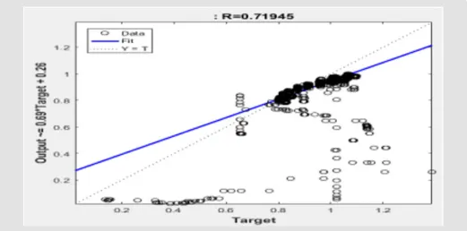
the atmosphere) for a report of 95,000 CUC, changing the current air flow regulation system by throttling by the use of variable speed drives. The behavior of the correlation coefficients for training,
validation, testing and adjustment of the artificial neural network identified are shown in Figure 13. As a result of the processing of 12198 data from a set of experiments (“Output” is assumed as the pressure of air in the collector calculated by the artificial neural model and “Target” the actual air pressure in the collector). Figure 9 shows the generalization of the network with 40476 data not presented during training, where a correlation coefficient of 0.71
Figure 13: Neural network correlation coefficients.
Possible Industrial Level Implementation of the Case
Study
In the background search conducted on artificial intelligence applied to control electronics to improve energy efficiency in
industrial ventilation, no specific references were found at the industry level. With the studies carried out so far, we can define three important technological elements and whose integration could allow us to realize the possible implementation of this project
at the industrial level (Figure14).
Figure 14: Network generalization.
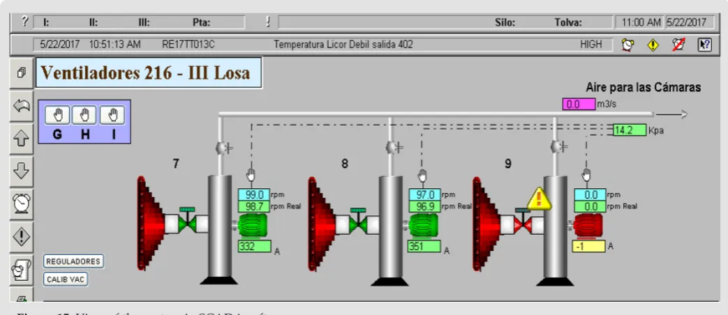
Current Plant Supervision System (SCADA)
A partial view of the current system of supervision of the Plant, case study, is shown in Figure 15. In this way the operator
or technician can review the behavior of all the variables in the
Figure 15: View of the system in SCADA software.
The PLC used for the Implementation of Said SCADA: which
has among its benefits, the implementation of the AI either in its Dif
-fuse Logic variant used in this project with Arduino Microcontrol
-ler, as of Neural Networks (result of the field experiments described in Slab 3 of the factory), as detailed in the bibliography consulted
in section 1.7. This device has a data-based analysis algorithm, it
is included in a module that adapts directly to the controller chas
-sis. Once installed, IA Project Sherlock takes advantage of a novel physics-based modeling to “learn” from the application managed by
the controller. The solution reviews the controller’s tags to identify
the application or allows users to choose what they would like to model by selecting the inputs and outputs through an additional instruction (AOI). The IA Project Sherlock will quickly learn from the data that passes through the controller to build a model. This process can be achieved in a matter of minutes. Large amounts of
historical data are not required, nor should the data leave the
auto-mation layer. Once the model is built, the Project Sherlock solution continuously observes the operation for anomalies by comparing it with its derived and principle-based understanding. If you detect a problem, you can activate an alarm on an HMI screen or panel.
Future iterations will go beyond diagnostics to direct users on how
to remedy a problem or automatically adjust system parameters to solve a problem without human intervention [9,10].
The Micromaster used in the Field Tests: can be configured for speed control through the PLC, as detailed in the bibliography
consulted in section 1.4. One of the ways to establish this connection between the PLC and the micromaster can be the remote mode
control. It is suitable for applications in which the variable changes of drives frequently made during the process. These changes can be made by the operator himself (by means of potentiometers, switches, rotary selectors or BCD, etc.). However, the most common situation is that the parameters of the drive are set by the process
control and supervision team, to which the frequency converter is connected: voltage and / or current regulators, limit switches, operator screens, sensors , etc., or even a personal computer and
/ or PLC. In the case of these remote controls, communication can
be carried out in two ways described in the bibliography consulted. The control equipment that regulates the drive is, in most cases, a PLC. The PLC connection with the process and other control elements, similar to the drive, can also be done through point-to-point connections, or through industrial communications buses. The integration of these three technological elements, identified by I, II and III, already present in the plant, with an adequate network of industrial communication, could conclude in an Artificial Intelligence Implementation Project to the Control Electronics of the drives that they supply combustion air in this specific industrial process, which would lead to a substantial improvement in their energy efficiency.
Conclusion
Artificial Intelligence algorithms can be implemented that
allow to establish the demand for air from a direct measurement
Submission Link: https://biomedres.us/submit-manuscript.php
Assets of Publishing with us • Global archiving of articles
• Immediate, unrestricted online access • Rigorous Peer Review Process • Authors Retain Copyrights
• Unique DOI for all articles
https://biomedres.us/ This work is licensed under Creative
Commons Attribution 4.0 License
ISSN: 2574-1241
DOI:10.26717/BJSTR.2020.25.004273
Deynier Montero Góngora.Biomed J Sci & Tech Res
the hidden layer and one in the output layer, with logsigmoidal and linear activation functions respectively, with Levenberg-Marquardt training algorithm, has been selected for its ability to approximate
nonlinear functions.
The proposed artificial neuronal model has been able to predict the air pressure in the collector with a 98% correlation and 71% in
its generalization.
References
1. Martínez E (2011) Speed regulation in Combustion Atmospheric Air Fans of the Reduction Furnaces plant. Electric. Moa: Undergraduate
thesis.
2. Santana EY, Marrero S (2013) Control of combustion air flow in
reduction furnaces. University of Camaguey. 2013. CYTDES International
Conference, Science and Technology for sustainable development.
3. Vega O (2015) Evaluation of the operational parameters of the combustion air supply in the Reduction Furnaces. Moa: Master thesis.
4. Valverde R, Gachet D (2007) Identification of dynamic systems using RBF neural networks. RIAI 4(2): 32-42.
5. Santos M (2011) An Applied Approach to Intelligent Control. RIAI 8(4): 283-296.
6. Habashi F (1997) Handbook of Extractive Metallurgy. sl: Wiley-VCH, Weinheim II.
7. Toro D (2017) Fan control alternatives in test bench for air flow. Unpublished Engineering Report. University of Camaguey. Camaguey,
Cuba.
8. Sutradhar A, Sengupta AY, Challa R (2010) Annual IEEE India Conference. sl: Department of Electrical Engineering, Bengal Engineering & Science University. Identification of Servo-driven Inverted Pendulum System using Neural Network.
9. Castle D (2017) Artificial Intelligence applied to Control Electronics to improve energy efficiency in Industrial Ventilation. Unpublished Engineering Report. University of Camaguey. Camaguey, Cuba.