Scholarship@Western
Scholarship@Western
Electronic Thesis and Dissertation Repository
1-15-2014
Structural and Durability Performance of Precast Segmental
Structural and Durability Performance of Precast Segmental
Tunnel Linings
Tunnel Linings
Safeer Abbas
The University of Western Ontario
Supervisor
Prof. Dr. Moncef Nehdi
The University of Western Ontario
Graduate Program in Civil and Environmental Engineering
A thesis submitted in partial fulfillment of the requirements for the degree in Doctor of Philosophy
© Safeer Abbas 2014
Follow this and additional works at: https://ir.lib.uwo.ca/etd
Part of the Civil Engineering Commons, and the Structural Engineering Commons
Recommended Citation Recommended Citation
Abbas, Safeer, "Structural and Durability Performance of Precast Segmental Tunnel Linings" (2014). Electronic Thesis and Dissertation Repository. 1865.
https://ir.lib.uwo.ca/etd/1865
This Dissertation/Thesis is brought to you for free and open access by Scholarship@Western. It has been accepted for inclusion in Electronic Thesis and Dissertation Repository by an authorized administrator of
(Thesis format: Integrated Articles)
by
SAFEER ABBAS
Graduate Program in Engineering Science Department of Civil and Environmental Engineering
A thesis submitted in partial fulfillment of the requirements for the degree of
Doctor of Philosophy
The School of Graduate and Postdoctoral Studies The University of Western Ontario
London, Ontario, Canada
ii
Abstract
Tunnels play a key role in assisting the movement of people, goods, and special services.
The functionality of tunnels depends on the structural and durability performance of its lining
system. Tunnel lining systems act as lines of defense against large overburden loads and
complex geotechnical surrounding conditions. The use of precast concrete tunnel linings
(PCTLs) has been escalating due to its efficient and economical installation process
compared to that of normal cast in-situ lining practice. Normally, PCTL segments are
designed for 100 years of service life. However, tunnel structures often suffer premature
degradation primarily due to reinforcement corrosion, which requires costly repair and
maintenance. Corrosion induces distress in PCTL leading to micro- and macro-cracking and
consequently spalling of the concrete cover, which in turn accelerates damage. Hence,
addressing and solving such durability-sustainability dilemma of precast tunnels is a must.
The main aim of this dissertation is to evaluate the structural and durability performance
of full-scale conventional reinforced concrete (RC) tunnel lining segments in comparison to
steel fibre-reinforced concrete (SFRC). Moreover, the potential for implementing ultra-high
performance fibre-reinforced concrete (UHPFRC) in precast tunnel lining systems was also
investigated. Tunnel lining segments behaviour was evaluated under simulated field-like
conditions including physical and chemical loads encountered during the service life of
PCTL segments.
Physical loads consisted of replicating loading conditions induced as a result of
surrounding ground stresses, ground settlement, rock expansion behaviour, vehicular
accidents inside tunnels and stresses induced by tunnel boring machines during installation of
PCTL segments. On the other hand, chemical loads were simulated by exposing PCTL
specimens to various chloride ions solutions while monitoring the changes in their visual
appearance, cracking patterns and mechanical degradation. Finally, finite element analysis
(FEA) was performed in order to verify the experimental findings.
Experimental results showed that the peak load capacity of RC PCTL segments was
higher than that of the corresponding SFRC segments; however, SFRC achieved higher
iii
comparable behaviour under thrust loading action without cracking and spalling of concrete,
indicating the adequate ability of segments to sustain TBM installation loads. The durability
assessment showed that the external specimens (extrados and intrados faces) of both the RC
and SFRC PCTL segments exhibited lower chloride ion penetration owing to surface
treatment using a cement slurry. The chloride ion diffusion coefficient was a function of the
exposure period and concentration of the salt solution. SFRC PCTL segments better resisted
the ingress of chloride ions than control RC segments. Results indicate that conventional RC
PCTL segments are more vulnerable to corrosion damage compared to that of SFRC PCTL
segments.
Moreover, the load carrying capacity of UHPFRC tunnel lining segments linearly
increased with higher fibre dosage and followed the rule of mixtures, regardless of the fibre
length. UHPFRC exhibited higher cracking resistance, leading to better durability properties
compared to that of conventional RC and SFRC owing to its very low porosity and denser
micro-structure. Furthermore, no deterioration of UHPFRC mechanical properties was
observed after various chloride ions exposures.
Based on structural and durability results, it can be concluded that the UHPFRC is a very
promising alternative for conventional RC and SFRC tunneling segments. The very high
strength and ultra-durable nature of UHPFRC can allow reducing the cross-sectional
dimensions of PCTL segments, leading to reduced material cost and more sustainable
construction. In addition, UHPFRC PCTL segments can eliminate the laborious and costly
manufacturing of curved shape steel cages, which mitigates the corrosion problem, leading to
enhanced service life of lining systems at low production cost.
Keywords: Precast; concrete; tunnel; linings; chloride; ions; corrosion; structural; durability;
fibre; reinforced concrete; ultra-high; performance; flexural, thrust, settlement; finite
iv
Co-Authorship Statement
This thesis was prepared according to the integrated-article layout designed by the
Faculty of Graduate Studies at Western University, London, Ontario, Canada. All the work
stated in this thesis including experimental testing, data analysis, finite element modeling and
writing draft manuscripts for publication was carried out by the candidate. The role of the
research supervisor and any other co-author (if applicable) was to advise, help in establishing
the experimental procedures, proof reading of initial drafts and to help in the development,
analysis and submission of the final version of manuscripts. The following publications have
been either accepted or submitted to peer-reviewed technical journals and international
conferences:
1) Abbas, S., Soliman, A. and Nehdi, M. (2013) “Mechanical performance of
full-scale RC and SFRC precast tunnel lining segments: A case study,” ACI Materials
Journal. Accepted
2) Abbas, S., Soliman, A. and Nehdi, M. (2013) “Experimental study on settlement
and punching behaviour of full-scale RC and SFRC precast tunnel lining
segments,” Engineering Structures, Elservier. Submitted
3) Abbas, S., Soliman, A. and Nehdi, M. (2012) “Chloride ions penetration in RC
and SFRC precast tunnel lining segments,” ACI Materials Journal. Submitted
4) Abbas, S., Soliman, A. and Nehdi, M. (2013) “Corrosion performance of RC and
SFRC precast tunnel lining segments,” Construction and Building Materials,
Elservier. Submitted
5) Abbas, S., Soliman, A. and Nehdi, M. (2013) “Effect of steel fibre length and
dosage on mechanical and durability performance of ultra-high performance
concrete,” Materials and Design, Elservier. Submitted
6) Abbas, S., Soliman, A. and Nehdi, M. (2013) “Mechanical performance of
ultra-high performance fibre-reinforced concrete tunnel lining segments,” Tunneling
v
7) Abbas, S., Soliman, A. and Nehdi, M. (2012) “Mechanical and durability
performance of RC and SFRC precast tunnel lining segments,” Tunneling
vi
Dedication
To,
My Father: Malik Fakhar HussainMy Mother: Nasreen Akhtar, “God bless her soul”
My Brothers: Ali, Fuzail and Ammer
My Sisters: Shamsa and Taskeen
vii
Acknowledgements
First of all, thanks to Almighty Allah for providing me such opportunities and
capabilities that led me towards the completition of this dissertation. I would like to state my
sincere appreciation and humble thankfulness to my worthy research advisor Prof. Dr.
Moncef Nehdi, for his invaluable guidance, supervision, encouragement and support
throughout this study.
I would like to acknowledge the contribution of the Canadian precast plant to this
research by providing the full-scale PCTL segments and helping in the coring of test
specimens at their site. Several companies including BASF and Lafarge are also appreciated
for their material donations.
Special thanks to the work-study undergraduate students who helped during the
specimens’ preparation for various tests. The role of the University Machine Shop in
fabricating the load and reaction frames and segment molds is appreciated. I would also like
to thank all technicians and staff members of the Department of Civil and Environmental
Engineering at Western University, Canada who helped during this research.
Finally, I would like to thank my father and mother (God bless her soul) who sacrificed a
lot in order to provide me with such opportunities that led me towards success. This degree
would have not been possible without their sincere encouragement and prayers throughout
my life. I would like to express my deep gratitude and appreciation to my brothers and
sisters. Furthermore, I would like to acknowledge my wife’s support, encouragement and
viii
Table of Contents
Abstract ... ii
Co-Authorship Statement ...iv
Dedication ...vi
Acknowledgements ... vii
Table of Contents ... viii
List of Tables ...xvi
List of Figures ...xix
List of Appendices ...xxvi
INTRODUCTION... 1
1.1. Tunnel Linings ... 1
1.2. Problem Statement ... 2
1.3. Proposed Solution ... 3
1.4. Research Needs and Motivation ... 4
1.5. Specific Research Objectives ... 5
1.6. Structure of the Thesis... 6
1.7. Original Contributions to Research ... 7
1.8. References ... 9
LITERATURE REVIEW ... 11
2.1. Corrosion Mechanism ... 11
2.2. Corrosion Effects in RC Structures ... 12
2.3. Causes of Corrosion ... 12
2.3.1. Carbonation ... 12
ix
2.4. Corrosion in Tunnel Linings ... 14
2.5. Ultra-High Performance Concrete ... 15
2.5.1. UHPC Composition and Mixture Design ... 15
2.5.1.1. Binders ... 16
2.5.1.2. Water/Binder Ratio ... 16
2.5.1.3. Superplasticizer ... 17
2.5.1.4. Aggregates ... 17
2.5.1.5. Steel Fibres ... 17
2.5.1.6. Nano-materials ... 18
2.5.2. Fresh Properties of UHPC ... 18
2.5.2.1. Fresh Temperature ... 18
2.5.2.2. Air Content ... 19
2.5.2.3. Setting Time ... 19
2.5.2.4. Workability ... 20
2.5.3. Mechanical Properties ... 20
2.5.3.1. Compressive Strength ... 20
2.5.3.2. Elastic Modulus ... 23
2.5.3.3. Flexural Strength ... 23
2.5.3.4. Fracture Energy ... 26
2.5.3.5. Fibre and Rebar Pull-Out (Bond Strength) ... 27
2.5.3.6. Reinforcement Cover ... 27
2.5.3.7. Shear Resistance ... 28
2.5.3.8. UHPC under Earthquake, Impact or Explosive Loadings ... 28
2.5.3.9. Fatigue Behaviour... 29
2.5.4. Durability Properties... 30
x
2.5.4.2. Chloride Ions Penetration Properties ... 31
2.5.4.3. Reinforcement Corrosion ... 32
2.5.4.4. Freeze-Thaw Damage and Surface Scaling ... 32
2.5.4.5. Alkali-Silica Expansion ... 32
2.5.4.6. UHPC under Fire ... 33
2.5.5. Cost Estimation and Sustainability of UHPC ... 33
2.5.6. Current Challenges for Implementation of UHPC ... 34
2.6. In-situ and Precast Concrete Tunnel Linings ... 35
2.7. Previous Studies on Tunnel Linings ... 36
2.8. References ... 38
FLEXURAL AND THRUST LOAD RESISTANCE OF FULL-SCALE RC AND SFRC PRECAST TUNNEL LINING SEGMENTS* ... 68
3.1. Introduction ... 68
3.2. Research Significance ... 69
3.3. Experimental Procedure ... 69
3.3.1. Segment Description and Mixture Design... 69
3.3.2. Core Sampling ... 70
3.3.3. Flexural Testing ... 70
3.3.4. Thrust Load Testing... 71
3.4. Results and Discussion ... 71
3.4.1. Compressive and Tensile Strengths ... 72
3.4.2. Flexural Monotonic Behaviour ... 72
3.4.2.1. Load-Displacement Curve ... 72
3.4.2.2. Cracking Pattern ... 74
3.4.3. Flexural Cyclic Behaviour ... 75
3.4.3.1. Hysteresis Curve ... 75
xi
3.4.3.3. Displacement Ductility ... 77
3.4.3.4. Stiffness Degradation ... 78
3.4.4. Thrust Load Test ... 78
3.5. Design Considerations... 78
3.6. Summary ... 80
3.7. References ... 81
SETTLEMENT AND PUNCHING BEHAVIOUR OF FULL-SCALE RC AND SFRC PRECAST TUNNEL LINING SEGMENTS* ... 94
4.1. Research Significance ... 94
4.2. Tunnel Linning Segment Description ... 95
4.3. Experimental Methodolgy and Setup ... 95
4.3.1. Settlement Response Testing ... 95
4.3.2. Punching Test ... 95
4.4. Results and Discussion ... 96
4.4.1. Settlement Behaviour ... 96
4.4.1.1. Load-Displacement Response ... 96
4.4.1.2. Cracking Pattern ... 97
4.4.2. Punching Behaviour ... 99
4.4.2.1. Load-Displacement Response ... 99
4.4.2.2. Cracking Pattern ... 100
4.5. Design Considerations... 101
4.6. Summary ... 102
4.7. References ... 103
CHLORIDE IONS PENETRATION IN RC AND SFRC PRECAST TUNNEL LINING SEGMENTS* ... 114
xii
5.2. Specimen Preparation ... 114
5.3. Chloride Ions Penetration Assessment ... 115
5.3.1. Sorptivity Test ... 115
5.3.2. Permeable Pore Space Test ... 115
5.3.3. Salt Ponding Test ... 116
5.3.4. Chemical Analysis of Chlorides ... 116
5.3.5. Rapid Chloride Ion Penetrability Test ... 117
5.3.6. Mercury Intrusion Porosimetry ... 117
5.4. Results and Discussion ... 117
5.4.1. Sorptivity Coefficient ... 117
5.4.2. Percentage of Permeable Voids ... 118
5.4.3. Chloride Profiles Parameters ... 119
5.4.3.1. Penetration of Chlorides ... 119
5.4.3.2. Diffusion Coefficient and Surface Chlorides ... 121
5.4.4. Electric Resistivity and Chloride Ions Penetration ... 123
5.5. Statistical Analysis using Factorial Design ... 124
5.6. Summary ... 125
5.7. References ... 126
CORROSION PERFORMANCE OF RC AND SFRC PRECAST TUNNEL LINING SEGMENTS* ... 140
6.1. Research Significance ... 140
6.2. Description of Full-Scale Tunnel Lining Segments and Mixture Design ... 141
6.3. Specimens Preparation for Corrosion Assesment ... 141
6.3.1. Core Sampling ... 141
6.3.2. Saw Cut Beams ... 141
6.3.3. Steel Rebars ... 141
6.3.4. Bond Pull-out Specimens ... 141
xiii
6.4.1. Salt Immersion Test Description ... 142
6.4.2. Testing and Measurements ... 142
6.5. Results and Discussion ... 143
6.5.1. Visual Inspection and Crack Patterns ... 144
6.5.2. Concrete Specimens Mass Change ... 146
6.5.3. Rebar Specimens Mass and Diameter Loss ... 147
6.5.4. Compressive Strength ... 147
6.5.5. Splitting Tensile Strength ... 148
6.5.6. Flexural Strength ... 149
6.5.7. Bond Strength ... 150
6.6. Service Life Prediction for Tunnel Lining Segments... 150
6.7. Summary ... 151
6.8. References ... 153
EFFECT OF STEEL FIBRE LENGTH AND DOSAGE ON MECHANICAL AND DURABILITY PROPERTIES OF ULTRA-HIGH PERFORMANCE CONCRETE* ... 166
7.1. Research Significance ... 166
7.2. Experimental Program... 167
7.2.1. Material Composition and Proportions... 167
7.2.2. Mixing of UHPC Constituents ... 167
7.2.3. Specimen Preparation and Environmental Conditions ... 167
7.2.4. Mechanical Testing ... 168
7.2.5. Durability Testing ... 168
7.2.6. Micro-structural Analysis ... 169
7.3. Results and Discussion ... 169
7.3.1. Fresh Properties ... 169
7.3.2. Compressive Strength and Modulus of Elasticity ... 169
7.3.3. Splitting Tensile Strength ... 171
xiv
7.3.4.1. Load-Deflection Behaviour ... 172
7.3.4.2. Toughness ... 173
7.3.4.3. Crack and Failure Pattern ... 174
7.3.5. Permeable Voids ... 175
7.3.6. Sorptivity Coefficients ... 176
7.3.7. Electrical Resistance of Chloride Ions ... 176
7.3.8. Chloride Ions Penetration ... 177
7.3.9. Effect of Chloride Ions Exposure on Mechanical Properties ... 177
7.4. Summary ... 178
7.5. References ... 179
STRUCTURAL BEHAVIOUR OF ULTRA-HIGH PERFORMANCE FIBRE-REINFORCED CONCRETE TUNNEL LINING SEGMENTS* ... 197
8.1. Reserch Significance ... 197
8.2. Experimental Program... 198
8.2.1. Material Composition and Mixing of UHPFRC... 198
8.2.2. Fabrication of UHPFRC Tunnel Lining Segments... 198
8.3. Experimental Procedure and Setup ... 198
8.3.1. Flexural Testing ... 198
8.3.2. Thrust Load Testing... 199
8.4. Finite Element Simulation ... 199
8.5. Results and Discussion ... 200
8.5.1. Flexural Performance of UHPFRC Tunnel Lining Segments ... 200
8.5.1.1. Load-Displacement Response ... 200
8.5.1.2. Toughness ... 202
8.5.1.3. Cracking Pattern ... 203
8.5.1.4. Rule of Mixtures ... 204
xv
8.6. Numerical Validation ... 205
8.7. Moment Capacity of Tunnel Linning Segments ... 206
8.8. Summary ... 207
8.9. References ... 209
SUMMARY, CONCLUSIONS AND RECOMMENDATIONS ... 223
9.1. Structural Performance of Tunnel Lining Segments ... 223
9.2. Durability Performance of Tunnel Lining Segments ... 224
9.3. Recommendations for Future Research ... 226
APPENDICES ... 228
xvi
List of Tables
Table 2.1 – Damaged/Corroded tunnels due to chloride ingress ... 55
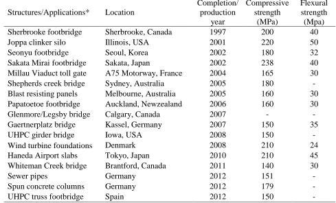
Table 2.2 – Example applications of UHPC around the world ... 55
Table 2.3 – Typical composition of UHPC ... 56
Table 2.4 – Effect of mixing time on fresh temperature of UHPC ... 56
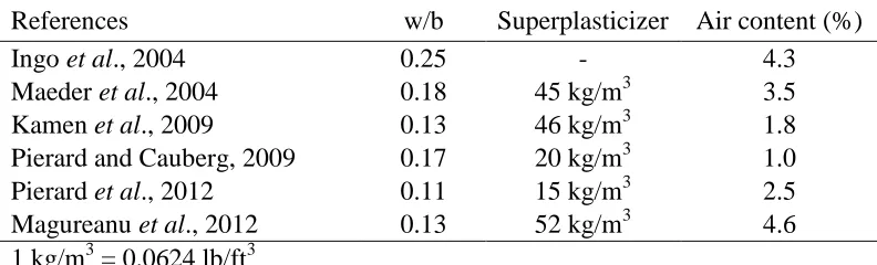
Table 2.5 – Effect of w/b and superplasticizer on air content of UHPC ... 56
Table 2.6 – Conversion factors for various type and size of UHPC specimens for compressive strength ... 57
Table 2.7 – Effect of pressure application on UHPC compressive strength ... 57
Table 2.8 – Relationship between elastic modulus and compressive strength of UHPC ... 57
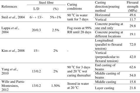
Table 2.9 – Effect of casting method on flexural capacity of UHPC ... 58
Table 2.10 – Effect of steel fibre dosage and beam size on flexural capacity of UHPC ... 59
Table 2.11 – Bond strength of steel fibre and rebar in UHPC ... 60
Table 2.12 – Fatigue behaviour of UHPC ... 61
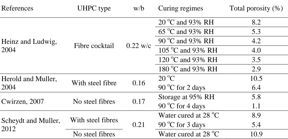
Table 2.13 – Effect of w/b and curing regime on UHPC porosity ... 62
Table 2.14 – UHPC water sorptivity coefficient ... 62
Table 2.15 – Maximum chloride ions penetration into UHPC ... 63
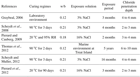
Table 2.16 – Chloride ions penetration depth into UHPC specimens for various salt exposures... 63
Table 2.17 – UHPC chloride ions diffusion coefficient for various curing exposures and w/b ... 64
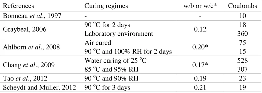
Table 2.18 – Number of coulombs passed through UHPC specimens ... 64
xvii
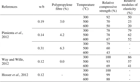
Table 2.20 – UHPC under elevated temperature ... 66
Table 2.21 – UHPC cost estimation ... 66
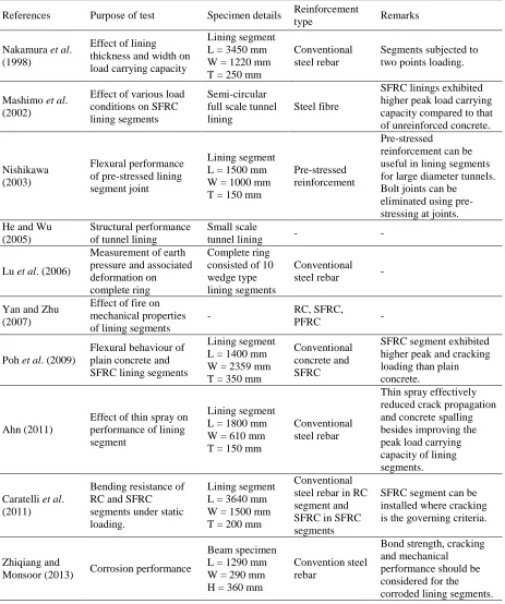
Table 2.22 – Various studies conducted on tunnel lining segments ... 67
Table 3.1 – Concrete mixture composition for RC and SFRC segments ... 84
Table 3.2 – Fresh and hardened properties of concrete mixture composition of full-scale RC and SFRC segments ... 84
Table 3.3 – Bending properties of SFRC ... 85
Table 3.4 – Flexural test results for RC and SFRC PCTL segments ... 85
Table 3.5 – Design results comparison for RC and SFRC PCTL segments ... 85
Table 4.1 – Settlement and punching test results for RC and SFRC PCTL segments ... 105
Table 4.2 – Monitored crack widths of PCTL segments ... 105
Table 4.3 – Damage criteria of tested PCTL segments ... 105
Table 4.4 – Comparison of experimentally predicted versus design values of settlement and punching load tests ... 106
Table 5.1 – Number and size of specimens for various tests ... 130
Table 5.2 – Sorptivity coefficient for RC and SFRC specimens ... 130
Table 5.3 – Diffusion coefficient and surface chloride for RC and SFRC specimens ... 131
Table 5.4 – RCPT results for RC and SFRC specimens ... 131
Table 5.5 – Factors and their levels for factorial analysis ... 132
Table 5.6 – Percentage contribution of factors ... 132
Table 6.1 – Specimen’s visual rating after chloride exposure ... 157
Table 6.2 – Crack width due to rebar corrosion in RC beam specimens ... 157
Table 6.3 – Mechanical properties of RC and SFRC specimens ... 158
xviii
Table 7.1 – Chemical and physical properties of used materials ... 182
Table 7.2 – UHPC mixture proportions ... 182
Table 7.3 – Coefficient of variance for 8 mm (0.31 in) steel fibres ... 183
Table 7.4 – Coefficient of variance for 12 mm (0.47 in) steel fibres ... 184
Table 7.5 – Coefficient of variance for 16 mm (0.62 in) steel fibres ... 185
Table 7.6 – Flowability, compressive strength and modulus of elasticity results ... 186
Table 7.7 – Splitting tensile strength of UHPC ... 186
Table 7.8 – Flexural properties of UHPC mixtures ... 187
Table 7.9 – Measured crack width during flexural test of UHPC beam specimens ... 187
Table 7.10 – VPV and sorptivity coefficient results for UHPC mixtures ... 188
Table 7.11 – Rapid chloride ion penetrability of UHPC mixtures under various chloride ion exposures... 188
Table 7.12 – Mechanical properties of UHPC specimens after various chloride exposures 189 Table 8.1 – Flexural results of UHPFRC tunnel lining segments... 212
Table 8.2 – Crack width results of tested UHPFRC tunnel lining segments ... 212
Table 8.3 – Comparison between experimental and finite element predicted peak load results for 1/3rd scaled-down UHPFRC segments ... 213
Table 8.4 – Comparison between experimental/finite element predicted full-scale RC, SFRC and UHPFRC results and design moment capacity of PCTL segments ... 213
Table A.1 – Geotechnical properties at job site where full-scale tested PCTL segments were installed ... 228
Table E.1 – Strength range for various concretes ... 248
xix
List of Figures
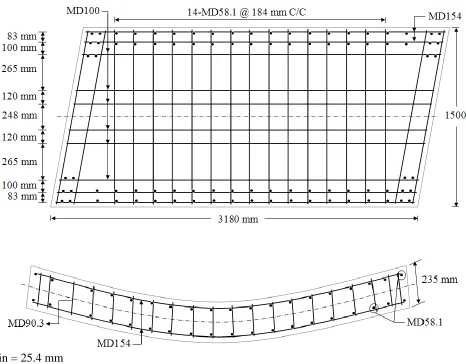
Figure 3.1 – RC segment dimensions and detailing. ... 86
Figure 3.2 – Flexural testing of PCTL segments, a) instrumentation test setup, b) waffle tree loading frame, and c) schematic of flexural test. ... 87
Figure 3.3 – Thrust load testing of segments, a) Experimental setup, b) Close view of loading area, and c) Schematic top view. ... 88
Figure 3.4 – Load-mid span displacement curves for RC and SFRC PCTL segments. ... 89
Figure 3.5 – Break down of lining segments. ... 89
Figure 3.6 – Failure surfaces of SFRC segments. ... 90
Figure 3.7 – Representation of crack patterns for a) RC and b) SFRC segments under static load. ... 90
Figure 3.8 – Cracks in RC and SFRC lining segments. ... 91
Figure 3.9 – Hysteresis curves for a) RC and b) SFRC PCTL segments under cyclic load. .. 91
Figure 3.10 – Skeleton and energy dissipation for a) RC and b) SFRC segments under cyclic load. ... 92
Figure 3.11 – Stiffness degradation for RC and SFRC segments under cyclic load. ... 92
Figure 3.12 – Thrust load test results for RC and SFRC segments. ... 93
Figure 4.1 – RC segment dimension and detailing. ... 107
Figure 4.2 – Settlement testing setup for PCTL segments, a) Experimental laboratory setup, and b) Schematic representation of laboratory setup. ... 108
Figure 4.3 – Punching test setup, a) Experimental laboratory setup, and b) Schematic representation of laboratory setup. ... 109
xx
Figure 4.5 – Failure surfaces of SFRC segment during settlement test. ... 110
Figure 4.6 – Schematic representation of cracking pattern in RC and SFRC segments during settlement test... 111
Figure 4.7 – Cracking pattern in RC and SFRC segments during settlement test. ... 111
Figure 4.8 – Load-displacement curve for punching test for RC and SFRC segments. ... 112
Figure 4.9 – Concrete flaking in RC segment during punching test. ... 112
Figure 4.10 – Cracking pattern of RC and SFRC segments during punching test. ... 113
Figure 4.11 – Punching failure pattern for RC and SFRC segments. ... 113
Figure 5.1 – Coring process from full-scale SFRC PCTL segments. ... 133
Figure 5.2 – Designation of internal and external specimens retrieved from full-scale PCTL segments. ... 133
Figure 5.3 – Sorptivity test results for RC specimens. ... 134
Figure 5.4 – Measured porosity in RC and SFRC specimens using MIP test. ... 134
Figure 5.5 – Chloride profiles for 3% NaCl ponding at 90 days for internal and external specimens of RC and SFRC PCTL. ... 135
Figure 5.6 – Chloride profiles for 3.5% and 10% NaCl at 90 days for internal specimens. . 135
Figure 5.7 – Chloride profiles for 3.5% NaCl for external specimens at 90 and 180 days. . 136
Figure 5.8 – Computer tomography (CT) analysis of internal RC and SFRC specimens, a) CT scan 3-D view of RC specimen, and b) Fibre distribution in SFRC specimen ... 137
Figure 5.9 – Void analysis using CT of internal RC and SFRC specimens, a) Voids in RC specimen, and b) Voids in SFRC specimen. ... 137
Figure 5.10 – Surface corrosion of steel fibres at the surface. ... 138
Figure 5.11 – SEM images of RC and SFRC specimens exposed to chloride solutions. ... 138
xxi
Figure 6.1 – Cutting of beams from full-scale PCTL segments. ... 159
Figure 6.2 – Surface degradation of concrete cylinder after 12 months of Cl- exposure. .... 159
Figure 6.3 – SEM image for Friedel’s salt compound. ... 160
Figure 6.4 – SEM image of hexagonal plates of chloro-aluminate. ... 160
Figure 6.5 – SEM image of cubical crystals of chloro-aluminate. ... 161
Figure 6.6 – Visual appearance of beam specimens exposed to 10% Cl- solution. ... 161
Figure 6.7 – SEM image of SFRC specimen exposed to 10% Cl- solution. ... 162
Figure 6.8 – Cracks in RC beam specimens after exposure to 10% Cl- solution. ... 162
Figure 6.9 – Visual rating of RC and SFRC specimens exposed to 3.5% and 10% Cl
-solutions. ... 163
Figure 6.10 – Mass loss of RC and SFRC specimens exposed to 3.5% and 10% Cl- solutions.
... 163
Figure 6.11 – Mass and diameter loss of bare steel rebar exposed to 3.5% and 10% Cl
-solutions. ... 164
Figure 6.12 – Optical microscopic images of fibre corrosion in SFRC specimen after 16
months of 10% Cl- exposure. ... 164
Figure 6.13 – Effect of exposure to 3.5% and 10% Cl- solutions on bond strength of steel
rebar to cementitious matrix. ... 165
Figure 6.14 – Rebar corrosion in bond pull-out specimens after exposure to various chloride
solutions. ... 165
Figure 7.1 – High shear pan mixer for mixing UHPC. ... 190
Figure 7.2 – Compressive strength behaviour of UHPC specimens. ... 190
Figure 7.3 – Flexural testing results of UHPC beam specimens. ... 191
xxii
Figure 7.5 – Average crack spacing for UHPC beam specimens incorporating various fibre
dosages. ... 192
Figure 7.6 – SEM images of UHPC specimen. ... 192
Figure 7.7 – SEM image of fibre-cementatious intimate contact. ... 193
Figure 7.8 – Measured porosity for UHPC mixtures incorporating various fibre lengths and
dosages. ... 193
Figure 7.9 – Sorptivity plot and chloride penetration into various UHPC specimens. ... 194
Figure 7.10 – Corrosion of surface steel fibres (salt ponding specimen incorporating 6% by
mixture volume of 8 mm (0.31 in) steel fibres). ... 194
Figure 7.11 – Optical and SEM images of surface fibre: a) Corrosion of surface fibre, b)
Penetration of corrosion in the embedded fibre (Section at S-S), c) SEM image, and d) EDX
analysis ‘E’... 195
Figure 7.12 – Deposition of salt material on the surface of UHPC specimens. ... 196
Figure 8.1 – Dimensions of tested UHPFRC tunnel lining segments... 214
Figure 8.2 – Experimental setup for flexural testing of UHPFRC tunnel lining segments. . 215
Figure 8.3 – Experimental setup for thrust load testing of UHPFRC tunnel lining segments.
... 215
Figure 8.4 – Finite element modeling of tunnel lining segment. ... 216
Figure 8.5 – Typical load-displacement curve for UHPFRC tunnel lining segments. ... 216
Figure 8.6 – Cracking and failure surface of tunnel lining segment. ... 217
Figure 8.7 – Toughness of UHPFRC lining segments for various fibre lengths and dosages.
... 217
xxiii
Figure 8.9 – Cracking pattern in tunnel lining segment incorporating 6% of the 16 mm (0.62
in) steel fibres. ... 219
Figure 8.10 – Effect of fibre length and dosage on crack spacing and peak load carrying
capacity of UHPFRC tunnel lining segments. ... 220
Figure 8.11 – Rule of mixtures for predicting the peak load capacity of UHPFRC segments.
... 220
Figure 8.12 – Thrust load results for UHPFRC tunnel lining segments. ... 221
Figure 8.13 – Cracking of tunnel lining segment without fibre addition during thrust load
testing. ... 221
Figure 8.14 – Finite element post-processing (stress contours) of UHPFRC tunnel lining
segment. ... 222
Figure 8.15 – Comparison of full-scale conventional RC, SFRC and UHPFRC tunnel lining
segments. ... 222
Figure B.1 – Concrete pouring into the segment mold using overhead bucket crane at precast
plant... 229
Figure B.2 – Covering the segment molds with plastic sheet during steam curing. ... 230
Figure B.3 – Demolding process of PCTL segment at fabrication plant. ... 230
Figure B.4 – Surface treatment process of PCTL segment at fabrication plant. ... 231
Figure B.5 – Storage of tunnel lining segments at precast plant. ... 231
Figure B.6 – Another view for experimental setup for flexural testing of lining segment. .. 232
Figure B.7 – Failure of full-scale tunnel lining segment. ... 232
Figure B.8 – Internal material disturbances in RC lining segment. ... 233
Figure B.9 – Cracking in SFRC lining segments. ... 234
xxiv
Figure C.1 – Coring operation from full-scale PCTL segments at precast plant site. ... 236
Figure C.2 – Retrieved cores from full-scale PCTL segments. ... 237
Figure C.3 – Water sorptivity test setup. ... 237
Figure C.4 – Rapid chloride ion penetrability and salt immersion tests specimens. ... 238
Figure C.5 – Rapid chloride ion penetrability test setup. ... 238
Figure C.6 – Specimens sawed cut from full-scale PCTL segments. ... 239
Figure C.7 – Cutting prisms from full-scale PCTL segments at precast plant site. ... 239
Figure C.8 – Rebar pull-out bond test specimens. ... 240
Figure C.9 – SFRC and RC core specimens immersed in chloride solution (Day 1) ... 240
Figure C.10 – Brownish color appeared in chloride solution due to corrosion of fibres in
SFRC specimens after one week. ... 241
Figure C.11 – Core specimens exposed to various chloride exposures inside a walk-in
environmental chamber. ... 241
Figure C.12 – Scanning electron microscope apparatus. ... 242
Figure C.13 – Salt deposition on beam specimens after chloride exposure. ... 242
Figure C.14 – Corrosion of rebar after exposure to chloride solution. ... 243
Figure C.15 – Cracking in RC specimens due to rebar corrosion. ... 243
Figure C.16 – Corrosion of surface steel fibres in SFRC specimens after 4 months of 3.5%
Cl- exposure. ... 244
Figure C.17 – Chloride penetration inside the hardened concrete specimen confirmed through
scanning electron microscopy analysis. ... 244
Figure D.1 – Inside view of mixer during mixing process of UHPFRC ingredients... 245
Figure D.2 – Crack measurement using crack width rule. ... 245
xxv
Figure D.4 – Salt immersion test for UHPFRC cylinder and beam specimens. ... 246
Figure D.5 – Crack localization and steel fibres bridging the crack in UHPFRC specimen. 247
Figure F.1 – Stress-strain curve (RILEM TC162-TD, 2003). ... 253
Figure F.2 – Stress-strain curve (AFGC-SETRA, 2002). ... 253
Figure G.1 – Cross-sectional dimensions of full-scale RC-PCTL segments. ... 258
Figure G.2 – Stress-strain diagram for SFRC (ACI 544, 2009). ... 258
xxvi
List of Appendices
Appendix A ... 228
Appendix B ... 229
Appendix C ... 236
Appendix D ... 245
Appendix E ... 248
Appendix F... 249
INTRODUCTION
Tunnels are defined as “the covered passage ways with vehicles or subways access that
is limited to portals regardless of structure types and construction techniques” according to
the American Association of State Highway and Transportation Officials (AASHTO)
Technical Committee for Tunnels. Tunnel structures do not include the enclosed highways,
subways or railways bridges (Hung et al., 2009). Road tunnel structures are mainly required
to overcome the physical obstructions (e.g. mountains or water bodies) in order to facilitate
existing highways, subways or railways (Hung et al., 2009). Tunnel structures significantly
reduce traffic congestions, leading to improved environmental quality parameters such as
noise and air pollution. Moreover, tunnels are viable means of protecting and preserving
surface landscapes, cultural heritages and historical buildings, leading towards green and
sustainable civil infrastructures (Hung et al., 2009).
1.1. TUNNEL LININGS
An important component of tunnel infrastructure is the tunnel lining systems. The
functionality of tunnels significantly depends on the structural and durability performance of
its lining system. Tunnel linings act as protective barriers against large overburden loads and
complex geotechnical surrounding exposure conditions. The use of precast concrete tunnel
lining (PCTL) systems in tunneling projects has been increasing as a result of its efficient and
economical application in comparison with the conventional in-situ lining technique (Elliott,
2002). PCTL segments are suitable for both soft and hard ground and can serve both as
preliminary and final support against large overburden loads (Hung et al., 2009).
Tunnel linings are normally constructed in a circular shape using tunnel boring machines
(TBMs). A number of precast segments are installed at the end of the TBM and assembled in
such a way it completes the circle of the tunnel lining (De Waal, 2000). The number of
segments required to complete a circle of the tunnel depends on many parameters including
thickness of segments varies from 200 to 300 mm (8 to 12 in) along with 1000 to 1500 mm
(40 to 60 in) width (Hung et al., 2009).
PCTL allows speedy construction along with superior quality due to enhanced control
during precast segment fabrication in precast plants. Moreover, the fabrication of PCTL
includes repetitive steps of batching and casting of concrete, which ultimately results in
wastage reduction compared to traditional in-situ concrete lining (Hariyanto et al., 2005).
Multi-disciplinary skills are required for the designing of PCTL segments in order to
meet their structural and durability performance. Thus, a detailed life-cycle analysis is
required in order to calculate the total fabrication and installation cost of PCTL systems that
satisfy specific design performance criteria (Hung et al., 2009). Generally, the required
service life of tunnel linings is considerably higher than that of other structures (e.g. bridges
and buildings) (Hung et al., 2009); therefore, special considerations should be given in
selecting the PCTL materials to satisfy the structural needs and result in long lasting life with
minimum maintenance requirements.
1.2. PROBLEM STATEMENT
Normally, PCTL segments are designed for 100 years of service life (Hung et al., 2009) with
conventional steel rebar reinforced concrete (RC). However, cases such as the Koblenz
Railway Tunnel, Switzerland; the London Underground Railway Tunnel, UK; and the
Michigan Northeast Raw Water Tunnel, USA all suffered premature deterioration before
achieving their respective service life. This was mainly attributed to reinforcement corrosion
induced by chloride ions penetration (ITA, 1991). Chloride ions from the underground water
can attack the extrados faces of PCTL, while de-icing salts carried by vehicular tires can
attack the intrados faces. Once these chloride ionsreach the embedded reinforcing rebar, it
disrupts the passive layer around the rebar and corrosion starts. The formation of corrosion
products can induce internal pressures in the concrete surrounding the corroded rebar, thus
leading to concrete cracking and spalling of the concrete cover (Uji et al., 1990). Moreover,
as the effective cross-section of the rebar decreases, the load carrying capacity of PCTL
The corrosion of reinforcing steel is the most costly and challenging deterioration
mechanism in RC structures. It was the primary reason for several dire structural collapses
such as a parking garage in Minnesota and the Berlin Congress Hall (Isecke, 1983; Borgand
et al., 1990). In Canada, the annual cost of repairing corrosion induced damage in RC
structures was estimated at $3 billion (Davis, 2000). In the United States, the reinforcement
corrosion problem costs the economy about $100 billion each year, nearly 1% of the nation’s
gross domestic product (Whitmore and Ball, 2004).
From a structural point of view, crack developments in RC PCTL segments during their
fabrication, delivery to the job site and installation process using TBM (due for instance to
accidental thrust and impact loads) will disturb its normal functioning. In addition, such
cracks will facilitate the intrusion of aggressive species, consequently accelerating the
corrosion process and leading to decreased structural strength. It was found that the chloride
ion diffusion into concrete was directly proportional to the developed crack width (Mangat
and Gurusamy, 1987; Tognazzi et al., 1998). Therefore, an alternative higher strength
material may be required for more crack resistant and more durable PCTL segments.
1.3. PROPOSED SOLUTION
It is well known that steel fibre-reinforced concrete (SFRC) can better resist crack formation
through the crack bridging action of steel fibres. Steel fibres can partially or completely
replace traditional reinforcing steel cages in several applications (Plizzari and Tiberti, 2006).
It is believed that steel fibres do not allow the onset and propagation of corrosion current due
to their discontinuous and dispersed nature. SFRC segmental linings have already been
successfully utilized in various tunnelling projects around the world, such as the Line 9
Subway Barcelona, the Madrid Subway, Spain; the Bright Water Sewer System Seattle,
USA; the Channel Tunnel Rail Link, UK and the Second Heinenoord Tunnel, the
Netherlands (Kooiman et al., 1998; King and Alder, 2001; Woods et al., 2003).
However, the complete replacement of conventional rebar cages with steel fibre
reinforcement is not always a feasible option due to higher structural strength requirements.
Therefore, an alternative high strength and ultra-durable material is required in order to
completely substitute for the conventional steel rebar in PCTL segments without affecting its
(UHPFRC) is an emerging cement-based composite with compressive strength typically
higher than 150 MPa (22 ksi) and almost negligible porosity (Graybeal, 2006). Therefore,
UHPFRC can be prove to be a more durable and sustainable material for PCTL fabrication.
In addition to improving structural and durability properties, complete substitution of
conventional steel rebar reinforcement with UHPFRC in tunnel linings can eliminate the
laborious and costly manufacturing of curved shape reinforcing rebar cages, which require
complicated welding and detailing. Furthermore, the cross-sectional dimensions of UHPFRC
lining segments can be reduced owing to its high strength properties, leading to more
economical construction.
1.4. RESEARCH NEEDS AND MOTIVATION
Tunneling engineers are increasingly specifying precast concrete tunnel linings (PCTLs) due
to its cost effectiveness and enhanced quality. However, the durability of conventional RC
PCTL segments is a major challenge facing tunneling stakeholders and transportation
authorities. In particular, corrosion of reinforcing steel in PCTL is a prominent deterioration
mechanism, requiring costly maintenance and repair. Therefore, a detailed study is required
in order to examine the physical (visual) and mechanical degradation of PCTL segments
under various corrosive environments.
Generally, the corrosion problem was studied by exposing small beams or prisms in the
laboratory under accelerated corrosive environment. However, the corrosion potential in
actual field tunneling specimens has so far been largely unexplored. While, the chloride ions
penetrability and build-up process in conventional concrete were well studied, to the best of
the author knowledge, only scant data on chloride penetrability and build-up process of
SFRC and UHPFRC are available in the open literature. Corrosion associated damage issues
such as visual appearance and cracking patterns, mass loss, compressive strength loss, tensile
strength loss and flexural strength loss on actual field PCTL specimens after various chloride
exposures are still lacking in the state-of-the art knowledge.
Furthermore, previous studies mainly focused on the static flexural resistance of PCTL
in order to evaluate its structural properties. However, the performance of full-scale PCTL
segments under cyclic loads that simulate their seismic behaviour still needs dedicated
forces induced as a result of vehicular accidents inside the tunnel and/or settlement due to
loose soil underneath the PCTL segments and expansion of rocks or other geotechnical
surrounding conditions were ignored in previous studies. Moreover, so far the flexural and
thrust load resistance of UHPFRC tunnel lining segments has not been investigated.
Therefore, this study was planned in order to fill these knowledge gaps regarding the
durability and structural properties of tunnel lining segments.
The findings of this study can motivate the use of UHPFRC PCTL segments, leading to
significant reduction in the PCTL production cost through saving the time and effort of
fabricating conventional rebar reinforcement cages, while mitigating costly maintenance and
repair of corrosion induced damage.
1.5. SPECIFIC RESEARCH OBJECTIVES
In order to accomplish the above-mentioned research needs, the specific research goals are as
follows:
1) Explore the flexural and thrust load resistance of full-scale conventional RC and
SFRC PCTL segments, along with their cyclic flexural behaviour in order to evaluate
their seismic performance.
2) Investigate the settlement and punching behaviour of full-scale RC and SFRC PCTL
segments in order to evaluate the effects of real field scenarios such as vehicular
accidents, settlement of soil underneath the segments and expansion behaviour of
surrounding rock formations.
3) Quantify the chloride ions penetration and corrosion potential of full-scale
conventional RC and SFRC PCTL segments to better estimate their durability
performance.
4) Establish materials and engineering properties of UHPFRC in order to characterize
the effects of the steel fibre length and dosage on the mechanical and durability
5) Evaluate the bending and thrust load resistance of UHPFRC tunnel lining segments
in order to establish its structural behaviour and verify experimental results through
finite element analysis to develop predictive capability for the engineering properties
of UHPFRC PCTL.
1.6. STRUCTURE OF THE THESIS
This dissertation has been prepared according to the integrated-article format predefined by
the Faculty of Graduate Studies at Western University, London, Ontario, Canada. It consists
of nine chapters covering the scope of this study: structural and durability performance of
RC, SFRC and UHPFRC tunnel lining segments. Chapter 1 provides an introductory
problem statement, research motivation, objectives and original contributions to research.
Chapter 2 reviews the state-of-the-art knowledge on the corrosion problem and its
mechanisms along with case studies on tunnel linings. Furthermore, a detailed literature
survey was conducted on the mechanical and durability properties of UHPFRC.
Chapter 3 presents the flexural and thrust load resistance of full-scale RC and SFRC
PCTL segments. Displacement at mid-span and cracking patterns for both segment types
were analyzed. Moreover, flexural cyclic tests were presented and discussed in this chapter in
order to evaluate its seismic behaviour.
Chapter 4 explains the experimental results of settlement and punching behaviour of the
full-scale RC and SFRC PCTL segments.
Chapter 5 outlines the chloride ions penetration properties of full-scale RC and SFRC
PCTL segments. Chloride diffusion coefficients for various exposure solutions and durations
were analyzed in order to evaluate the concrete quality used in fabricating the full-scale
tunnel lining segments.
Chapter 6 deals with the corrosion potential of full-scale RC and SFRC PCTL
segments. The loss in mechanical properties and physical deterioration due to various
chloride exposures of specimens (cores and sawed beams) retrieved from full-scale RC and
Chapter 7 presents the experimental evaluation of the UHPFRC material properties.
The effects of the steel fibre length and dosage on the mechanical and durability properties of
UHPFRC were discussed.
Chapter 8 evaluates the structural behaviour of UHPFRC tunnel lining segments.
Furthermore, finite element analysis using commercially available software ABAQUS was
conducted in order to verify the experimental behaviour and comparison of the performance
of UHPFRC with RC and SFRC tunnel lining segments was presented in this chapter.
Chapter 9 summarizes the research conclusions and future recommendations.
1.7. ORIGINAL CONTRIBUTIONS TO RESEARCH
This research addresses a practical and full-scale infrastructure problem: substantial financial
resources are spent worldwide for the maintenance and repair of tunnel linings because of
their premature deterioration. In the first phase of this study, actual full-scale precast tunnel
lining specimens, manufactured for a subway tunnel in Canada, were investigated for their
structural and durability properties in order to realistically simulate field conditions. The
second phase of this research program evaluates the potential of UHPFRC for the fabrication
of tunnel lining segments. This research should benefit both the design engineer and
tunneling contractors, since it provides a more durable and sustainable design solution to
mitigate the corrosion and associated damage while yielding enhanced mechanical and
structural behaviour, which should result in substantial savings in the initial cost and life
cycle maintenance and repair. The key original contributions of this research include:
1) A detailed investigation and comparison of bending and thrust load resistances of
full-scale RC and SFRC PCTL segments will provide a benchmark for tunneling
engineers in assessing the prototype capacities of segmental linings. Furthermore, the
evaluation of the cyclic behaviour of tunnel lining segments adds to the existing
knowledge on the structural seismic behaviour of full-scale PCTL segments.
2) The settlement and punching behaviour of full-scale RC and SFRC PCTL segments
as vehicular accidents, surrounding ground settlement and expansion behaviour of
rocks.
3) The chloride ions penetration and corrosion initiation process in full-scale RC and
SFRC PCTL segments were examined by simulating realistic field conditions and
environmental exposures. Herein, the developed experimental data should allow
engineers to further improve the durability design of PCTL segments.
4) The development of detailed database on the engineering and material properties of
UHPFRC mixtures suitable for industrial fabrication of full-scale PCTL segments
should represent a quantum leap in the tunneling industry.
5) It was demonstrated that complete replacement of conventional steel rebar
reinforcement in tunnel lining segments can be made using UHPFRC owing to its
exceptional structural and durability properties. Therefore, this study should provide
a source of inspiration and a comfort level to tunneling engineers, pre-casters,
contractors and clients in order to explore the development of novel UHPFRC PCTL
with unique durability performance.
6) It was observed that the initial cracking load of UHPFRC tunnel lining segments is
much higher than that of conventional RC and SFRC segments. Therefore, the
durability properties of PCTL can be better ensured by utilizing this promising
UHPFRC tunneling system.
7) The excellent engineering properties and durability of UHPFRC tunnel lining
segments should allow reducing the lining thickness, thus leading to decreased
self-weight. This will facilitate the handling and installation of tunnel lining segments at
the job site.
It is expected that the present study could develop into an UHPFRC PCTL initiative in
North America in the near future. Furthermore, it is envisioned that the development of such
UHPFRC super-durable tunnel lining segments could increase the interest in replacing the
conventional steel rebar RC lining segments, leading to more durable and sustainable
1.8. REFERENCES
Borgand, B., Warren, C., Somayagi, S. and Heidersbach, R., (1990), “Mechanisms of
corrosion of steel in concrete,” ASTM STP 1065, American Society of Testing and
Materials, Philadelphia, pp. 174-188.
Broomfield, P., (2007), “Corrosion of Steel in Concrete: Understanding, Investigation and
Repair,” Second Edition, Taylor and Francis, USA, 277 p.
Davis, J., (2000), “Corrosion: Understanding the Basics,” ASM International, The Materials
Information Society, Materials Park, Ohio, USA, 571 p.
De Waal, R., (2000), “Steel fibre-reinforced tunnel segments-for application in shield driven
tunnel linings,” PhD Thesis, Delft University of Technology, Netherlands, 240 p.
Elliott, K., (2002), “Precast Concrete Structures,” 1st Ed., Butterworth-Heinemann, Boston,
375 p.
Graybeal, B., (2006), “Material property characterization of ultra-high performance
concrete,” FHWA-HRT-06-103, U.S. Department of Transportation, 176 p.
Hariyanto, A., Kwan, H. and Cheong, Y., (2005), “Quality control in precast production: A
case study on tunnel segment manufacture,” Dimensi Teknik Arsitektur, Vol. 33, No. 1,
pp. 153-164.
Hung, C., Monsees, J., Munfah, N. and Wisniewski, J., (2009), “Technical Manual for
Design and Construction of Road Tunnels - Civil Elements,” FHWA-NHI-10-034, US
Department of Transport Federal Highway Administration, 702 p.
http://www.fhwa.dot.gov/Bridge/tunnel/pubs/nhi09010/01.cfm: assessed on 14 Decemeber,
2012.
Isecke, B., (1983), “Failure analysis of the collapse of the Berlin Congress Hall,” Corrosion
of Reinforcement in Concrete Structures, Ellis Harwood, Chichester, England, pp. 79-90.
ITA Working Group on Maintenance and Repair of Underground Structures, (1991), “Report
on the damaging effects of water on tunnels during their working life,” Tunneling and
King, R. and Alder, J., (2001), “The practical specification of steel fibre-reinforced concrete
(SFRC) for tunnel linings,” Proceedings of Underground Construction 2001 Conference,
London, published by Brintex Ltd., 12 p.
Kooiman, A., Van der Veen, C. and Djorai, M., (1998), “Steel fibre-reinforced concrete
(SFRC) tunnel segments suitable for application in the Second Heinenoord Tunnel,”
Proceedings of the 8th Congress on Challenges for Concrete in the Next Millennium,
Amsterdam, the Netherlands, pp. 719-722.
Mangat, S. and Gurusmany, K., (1987), “Long-term properties of steel fibre-reinforced
marine concrete,” Materials and Structures, Vol. 20, No. 4, pp. 273-282.
Plizzari, G and Tiberti, G., (2006), “Steel fibres as reinforcement for precast tunnel
segments,” Tunneling and Underground Space Technology, Vol. 21, No. 3-4, pp.
438-439.
Tognazzi, C., Ollivier, J., Carcasses, M. and Torrenti, J., (1998), “Couplage
Fissuration-Dégradation Chimique des Matériaux Cimentaires: Premiers Résultats sur les Propriétés
de Transfert (Chemical coupling cracking-cementitious materials degradation: First results
on transfer properties),” Ouvrages Géomatériaux et Interactions, Paris, pp. 69-84.
Uji, K., Matsuoka, Y. and Maruya, T., (1990), “Formulation of an equation for surface
chloride content of concrete due to permeation of chlorides,” Corrosion of Reinforcement
in Concrete, London, UK, pp. 258-267.
Whitmore, D.W. and Ball, J.C., (2004), “Corrosion Management,” ACI Concrete
International, Vol. 26, No. 12, pp. 82-85.
Woods, E., May, R., Hurt, J. and Watson, P., (2003), “Design of bored tunnels on Channel
Tunnel rail link, UK,” Rapid Excavation and Tunneling Conference Proceedings, pp.
LITERATURE REVIEW
Concrete is highly alkaline in nature (i.e. pH of 12 - 13) due to presence of sodium,
calcium and potassium oxides in its pore structure. These oxides assist in the formation of a
passive layer around the steel rebar. The passive layer is basically a thin and impenetrable
film of metal oxides and cement minerals, which protects the steel rebar and does not allow
the initiation of corrosion activity (Broomfield, 2007; ACI 222, 2001).
2.1. CORROSION MECHANISM
The reinforcing steel rebar corrosion in concrete memebers is similar to an electrochemical
reaction where the pore solution in the concrete matrix works as an electrolyte, while the
reinforcing steel rebar acts as an electrical conductor (ACI 222, 2001). The corrosion initiates
due to the release of electrons during the oxidation process at the anode (Eq. 2.1). These
electrons are utilized at some other location in order to maintain electrical neutrality.
Therefore, electrons are collected at the cathodic site where hydroxyl ions form upon reaction
with oxygen and water (Eq. 2.2) (Broomfield, 2007).
Eq. 2.1
Eq. 2.2
It should be noted that the anodic and cathodic reactions are the initial steps of forming
corrosion or rust. The availability of oxygen and moisture are the main controlling factors
that accelerate the corrosion process. Several reactions occur between iron and hydroxyl ions
in the presence of oxygen and moisture to form rust. Equations 2.3 to 2.5 show the series of
chemical reactions that take place during the corrosion process (Broomfield, 2007).
Eq. 2.3
Eq. 2.5
Where, n in Eq. 2.5 is variable depends on the availability of oxygen and water.
2.2. CORROSION EFFECTS IN RC STRUCTURES
The corrosion of steel reinforcement has detrimental effects on the normal functioning of RC
structures. A reduction in rebar diameter takes place, which adversely affects the
performance of RC structure due to a decrease in flexural capacity. This can significantly
reduces the service life of RC structures. Furthermore, the volume of rust can be 6 to 10
times more than the actual volume of steel. Therefore, this excess volume exerts pressure on
the concrete in the surrounding area, leading to micro- and macro-cracking and consequently
concrete spalling take place when it exceeds the tensile strength of concrete. Initially, some
rust stains and hair-line cracks are observed at the surface. These cracks map the rebar
locations and provide an easier access for the intrusion of oxygen, moisture and harmful
species which further accelerates the damage. The sectional loss due to spalling of concrete
decreases the cross-sectional dimensions of the structural elements, leading to reduced load
carrying capacity and possibly structural safety risks (Broomfield, 2007).
2.3. CAUSES OF CORROSION
The corrosion of reinforcing steel initiates with the disruption of the passive layer around
steel rebars. There are two main mechanisms, i.e. carbonation and chloride ions attack that
can break the passive layer and disturb the integrity of structural elements (Broomfield, 2007;
ACI 222, 2001).
2.3.1. Carbonation
Carbonation is the chemical reaction between the alkaline hydroxides in concrete and carbon
dioxide (CO2) from the surrounding environment (Eq. 2.6). This will form carbonic acid
(H2CO3) which neutralizes the alkaline phase of concrete. The calcium hydroxides (Ca(OH)2)
present in the pore solution react with H2CO3 and lower down the pH value due to the
passive layer is disturbed, leaving the steel rebar unprotected against corrosion activity
(Broomfield, 2007).
Eq. 2.6
Eq. 2.7
The carbonation induced corrosion depends on many factors including concrete quality
and porosity, concrete cover and the carbon dioxide percentage in the surrounding
environment (Broomfield, 2007). Carbonation can be easily monitored using a pH indicator.
The application of a phenolphthalein indicator on the exposed concrete surfaces becomes
clear at low pH regions, indicating carbonation activity, and changes color to pink for
un-carbonated regions (Broomfield, 2007).
2.3.2. Chloride Ions Attack
Chloride induced corrosion is one of the most costly and challenging deterioration
mechanisms facing civil infrastructure engineers and other industry stakeholders. Chlorides
can be present inside the concrete due to the use of sea water, addition of accelerators or
chloride polluted aggregates. Other sources of chlorides include sea salt spray or direct sea
water wetting and drying in case of offshore structures and the use of de-icing salts
(Broomfield, 2007). It was estimated that around 10 million tonnes of de-icing salt are
sprayed on highways/freeways every year in North America (TRB, 1991). Therefore,
concrete highways, bridges and tunnels are highly vulnerable to chloride induced corrosion.
Chloride ions attack the embedded reinforcement by disturbing the passive layer. The
ferrous ions at the anode react with the chloride ions to form a soluble compound. This
soluble compound turns into an insoluble compound iron hydroxide at the cathode, leaving
the chloride ions. The free chloride ions are again available at the anode to eliminate iron
ions from the steel rebar reinforcement and the process continues (ACI 222, 2001).
The penetration/intrusion of chloride ions into hardened concrete matrices is mainly due
to a diffusion process (Bamforth and Chapman-Andrews, 1994; Polder and Larbi, 1995).
concrete. Considering non-steady state situations (i.e. the concentration changes with time),
the law can be expressed as shown in Eq. 2.8 (Crank, 1975):
Eq. 2.8
Where, C is the chloride ions content; D is the chloride diffusion coefficient; t is the chloride
exposure period, and x is a depth variable. This equation can be solved using the following
boundary conditions (Crank, 1995; Stanish et al., 1997): (i) the chloride content at the
surface remains constant (x = 0, t > 0 → C = Co); (ii) initially, the chloride ions content in the
concrete is zero (x > 0, t = 0 → C = 0); and (iii) the chloride ions content is zero at a very far
distance from the surface (x = ∞, t > 0 → C = 0). Applying these boundary conditions and
substituting in Eq. 2.8, the Cl- concentration can be expressed as follows (Crank, 1995;
Stanish et al., 1997):
[ (√ )] Eq. 2.9
Where, Co is the surface chloride content and erf is the error function.
The barrier against Cl- to reach and attack the embedded steel reinforcement is the
concrete cover. Increasing the concrete cover thickness and/or reducing its permeability will
delay the corrosion initiation and extend the propagation period, which improves corrosion
durability. However, the concrete cover thickness cannot be increased beyond certain limits
due to structural, dimensional restrictions and practical reasons (Sibbick, 1993).
2.4. CORROSION IN TUNNEL LININGS
Generally, tunnel structures are subjected to both mechanical and environmental loads due to
high in-situ soil stresses and atmospheric pollution (Usman and Galler, 2013). Highways or
subways tunnel structures are more vulnerable to chloride induced corrosion due to their
underground construction below the water table, leading to reduced load carrying capacity
(Zhiqiang and Mansoor, 2013), and consequently life threatening risks. Furthermore, in
railway tunnels, the stray currents generated at the traction due to rail movements accelerate
the chloride build-up process and further aggravate the situation (ITA, 1991). Chlorides may
tunnel linings (FHWA, 2005; Hung et al., 2009). Moreover, the intrados faces of tunnel
linings may also get corroded due to de-icing salts carried by vehicular tires. Table 2.1
shows case histories of various tunnels which got corroded mainly due to chloride ions
ingress (ITA, 1991).
2.5. ULTRA-HIGH PERFORMANCE CONCRETE
Ultra-high performance concrete (UHPC) is a novel construction material exhibiting
enhanced mechanical and durability properties, which can lead to economical construction
through reducing the cross-sections of structural members leading to materials savings and
lower installation and labor costs (Tang, 2004). The relatively high initial cost of UHPC has
restricted its wider use in the construction industry. However, ongoing research and
investigations are filling knowledge gaps in order to commence innovative UHPC having
reduced initial cost.
Furthermore, the development and wide acceptance of an UHPC design code should
encourage stakeholders in the construction industry to implement large scale applications.
Examples of UHPC potential applications include the construction of new structures,
rehabilitation works, architectural structural and non-structural elements, machine parts and
military structures. Table 2.2 shows some of these applications around the world.
2.5.1. UHPC Composition and Mixture Design
The key factor in producing UHPC is to improve the micro and macro properties of its
mixture ingredients to ensure mechanical homogeneity, maximum density and dense particle
packing (Schmidt and Fehling, 2005; Shah and Weiss, 1998; Vernet, 2004; Wille et al.,
2011). The particle size distribution should be selected in such a way that the bigger size
particles be surrounded by at least two layers of smaller size particles. For instance, Richard
and Cheyrezy (1995) proposed an optimum ratio of 13; the bigger to smaller size particles to
achieve dense microstructure (i.e. the cement particle size should be 13 times smaller than
the fine aggregate size). Table 2.3 shows the range of UHPC constituents used in various