Performance Analysis of Fuzzy based MRAC
and Sliding Mode Controls of Vector
Controlled Induction Motor Drive
L. Sagar1, Dr. B. Sarvesh2
Research Scholar, Department of EEE, JNTUA, Ananthapur, Andhra Pradesh, India1 Professor, Department of EEE, JNTUK, Kakinada, Andhra Pradesh, India2
ABSTRACT: This paper presents the fuzzy based MRAC and sliding mode controls for Indirect vector controlled induction motor drive. In high performance AC drives the motor speed should closely match with the specified reference speed irrespective of the variations in the load, motor parameters and model uncertainties. Soft computing technique – Fuzzy logic is applied in this paper for the speed control of induction motor to achieve maximum torque with minimum loss. The fuzzy logic controller is implemented using the Field Oriented Control technique as it provides better control of motor torque with high dynamic performance. The proposed adaptive controller takes advantage of Model reference adaptive control and fuzzy logic control. An integrated mathematical model of the control scheme has been developed and simulated in MATLAB for Indirect vector control of an Induction motor. The simulated performances of the FL-MRAC slip gain tuner based IVCIM drive is compared to fuzzy based sliding mode controller. Simulation results conclude that the proposed Fuzzy based controller showed increased dynamic performance.
KEY WORDS: Induction motor, Field Oriented Control, Fuzzy logic Controller, Model reference adaptive control (MRAC) and Sliding Mode Control.
I. INTRODUCTION
AC Induction motors are being applied today to a wider range of applications requiring variable speed. field-oriented control technique has been widely used in industry for high-performance induction machine (IM) drive, where the knowledge of synchronous angular velocity is often necessary in the phase transformation for achieving the favorable decoupling control. However the speed control of the induction motors are not simple difficulties due to its complex and nonlinear mathematical model which involves parameters that vary with temperature, frequency and other operating conditions. The variations of parameters have significant effect on the accuracy of control speed and torque and other operating performance of the motor. It is therefore essential to optimize the motion control performance by designing intelligent adaptive controller based on fuzzy logic, neural network and expert systems; so that torque and flux have dynamic ideal response in high performance AC drives.
description of controllers are in Section 4. In section 4, the fuzzy based controller is proposed. Also the adaptive fuzzy based sliding mode control and fuzzy based MRAC are proposed. Simulation results are shown in Section 5. Finally, the paper is concluded in Section 6.
II. INDUCTION MOTOR MODELING
An Induction Motor of uniform air gap, with sinusoidal distribution of mmf is considered and the dynamic model [2] of the induction motor is derived by transforming the three phase quantitiesinto two phase direct and quadrature axes quantities. The equivalence between the three-phase and two-phase machine models [1] is derived from the concept of power invariance: the power must be equal in the three phase machine and its equivalent two-phase model. The d and q axes mmfs are found by resolving the mmfs of the three phases along the d and q axes. The mathematical model of the 3-phase IM could be represented by an equivalent 2-phase, where ds, qs, drand qr correspond to the stator, rotor, direct and quadrature axes, respectively. The stator voltage equations formulated from stationary reference frame and the rotor voltage equations formulated to the rotating frame fixed to the rotor.The 3-phase stator and rotor voltage equations written in vector-matrix can be further transformed into 2-phase stator and rotor voltage equations using the well-known Park's transformation. The 3-phase stationary reference frame variables as-bs-cs are transformed into 2-phase stationary reference frame variables (ds–qs). Furthermore, these 2-phase variables are transformed into synchronously rotating reference frame variables (de–qe) and vice-versa.
The stator circuit equations can be modeled as follows:
s s s
qs s qs qs
d
v
R i
dt
- --- (2.1)
s s s
qs s ds qs
d
v
R i
dt
--- (2.2)
Equations (2.1) and (2.2) are further converted into de–qeframe. The flux linkage expressions in terms of the currents can be written as
(
)
qs
L i
ls qsL i
m qsi
qr
--- (2.3)
(
)
qr
L i
lr qrL i
m qsi
qr
--- (2.4)
(
)
qm
L i
m qsi
qr
--- (2.5)
(
)
ds
L i
ls dsL i
m dsi
dr
--- (2.6)
(
)
dr
L i
lr drL i
m dsi
dr
--- (2.7)
(
)
dm
L i
m dsi
dr
--- (2.8)
2
re L m L
d
d
T
T
j
T
J
dt
P
dt
--- (2.9)
where TL is the load torque, J is the rotor inertia and ωm is the mechanical speed of the IM. Resolving the variables into
de–qe components, we obtain
3
2
2
e dr qr qr dr
P
T
i
i
--- (2.10)The dynamic machine model in stationary frame can be derived simply by substituting ωe= 0 . The corresponding stationary frame equations are given as follows:
s s s
qs s qs qs
d
v
R i
dt
--- (2.11)
s s s
ds s ds ds
d
v
R i
dt
--- (2.12)
0
R i
r sqrd
sqr r sdrdt
--- (2.13)
0
R i
r sdrd
sdr r sqrdt
--- (2.14)
The torque Equations can also be written with the corresponding variables in the stationary frame as follows:
3
2
2
s s s s
e dr qr qr dr
P
T
i
i
--- (2.15)The equations (1) and (15) form the mathematical model equations of a three phase induction motor.
III. VECTOR CONTROL OR FIELD ORIENTED CONTROL (FOC)
The Vector Control or Field Oriented Control is used to control Induction motor like a dc motor. Using vector control strategy, the torque and flux components can be controlled independently like dc motor. The basic principles of vector control can be explained with the help of dynamic model of induction motor where we need to convert 3Φ
quantities into 2-axes system by 3Φ/2Φ transformation called d-q machine model.There are two methods of vector control, Direct Vector Control method & Indirect Vector Control (IFOC) method. In indirect vector control strategy rotor flux vector is estimated using the field oriented control equations requiring a rotor speed measurement. Due its implementation simplicity, Indirect Vector Control method is more popular than Direct Vector Control in industrial applications.
3.1 INDIRECT FIELD ORIENTED CONTROL (IFOC)
In the Indirect Vector Control method, by using summation of rotor speed and slip frequency, the rotor flux angle is calculated. Hence the unit vectors are obtained indirectly. Then the d-q axis currents are obtained from the torque and flux producing components of stator current.
e e
dt
r stdt
r st
--- (3.1)
The rotor circuit equations
0
dr r m
dr r ds sl qr
r r
d
R
L
R i
dt
L
L
0
qr r m
qr r qs sl dr
r r
d
R
L
R i
dt
L
L
--- (3.3)
For decoupling control Ψqr = 0 ,So the total flux Ψ r directs on the de
axis.
Now from equations 3.1 and 3.2, we getdr m r r ds r r
d
L
L
i
R
dt
L
---- (3.4)
As well , the slip frequency can be calculated as
qs
m r r
sl qs
r r r ds
i
L
R
R
i
L
L i
---- (3.5)
The slip gain is
sl m r
s
qs r r
L R
K
i
L
---- (3.6)It is found that the ideal decoupling can be achieved if the above slip angular command is used for making field orientation. The constant flux Ψ r and Ψr I= 0can be substituted in equation 3.4 , so that rotor flux sets as
r
L i
m ds
---- (3.7)
The electromechanical torque developed is given by
3
2 2
m
e r qs
r
L
P
T
i
L
---- (3.8)IV. CONTROLLERS DESIGN
Speed controller is necessary to control the speed of the induction motor drive. Design of this speed controller greatly affects the performance of the electric drive. PI controllers are the most commonly used speed controllers before the introduction of fuzzy controller. Design and tuning of the fuzzy based controllers are defined in this section.
4.1 FUZZY LOGIC CONTROLLER
Fuzzy Logic implementation requires no exact knowledge of a model. The block diagram of a FLC is shown in Fig. 4.
4.2 PROPOSED ADAPTIVE FUZZY CONTROL SCHEMES
4.2.1 Fuzzy based SLIDINGMODE CONTROL BASIC CONCEPT
The basic principle of the sliding mode control consists in moving the state trajectory of the system toward a surface
S(X ) = 0 and maintaining it around this surface with the switching logic function Un . The basic sliding mode control law is expressed as.
= + --- (4.1)
This expression uses two terms, Ueq and Un . Ueq : is determined off line with a model that represents the plant asaccurately as possible. It is used when the system state is in the sliding mode. The term Un : is a sign function defined as Un= k sgn(S(X)), where
( ) = , ( ) < 0
− , ( ) > 0 --- (4.2)
This will guarantee that the state is attracted to the switching surface by satisfying the Lyapunov stability criteria .
( ) ( )̇ < 0 --- (4.3)
This strategy enforces the system trajectory to move toward and to stay on the sliding surface from any initial condition.Using a sign function often causes chattering in practice. One solution to reduce chattering is to introduce a boundary layer around the sliding surface [5], [6]. This is expressed by:
= ԑ ( ), | ( )| <ԑ
( ) , | ( )| >ԑ --- (4.4)
with k , a positive coefficient and ԑ, the thickness of the boundary layer. However, a small value of S might produce a boundary layer so thin that it can excite high frequency dynamics.
4.2.1.1 IM SLIDING MODE CONTROL
The ‘d’ axis, has the stator current component (Ids) loop and the ‘q’ axis allows the control stator current component (Iqs), whereas the external loop provide the regulation of the speed.
A. Speed SMC
Under field oriented assumptions, the electromagnetic torque can be expressed as:
= ( ) ∗
= --- (4.5)
Basically, the control law for Tm_ is divided into two parts: equivalent control Um9 which defines the control action when the system is on the sliding mode and switching part U: which ensures the existence condition of the sliding mode. If the friction kf is neglected expressions for Ueq and Us can be written as:
= ( )
= − ( ( )) --- (4.6)
To guarantee the existence of the switching surface consider a Lyapunov function [6, 9]:
Based on Lyapunov theory, if the function VG_t_ is negative definite, this will ensure that the system trajectory will be driven and attracted toward the sliding surface s(t) and once reached, it will remain sliding on it until the origin is reached asymptotically.
( ) ̇ = S(t) { − ( ) − ( )} ≤ --- (4.8)
To ensure that above function will be always negative definite, the value of the hitting control gain β should be
designed as the upper bound of the lumped uncertainties d(t), i.e.
≥ | ( )| --- (4.9)
Therefore the speed control law defined previously will guarantee the existence of the switching surface s(t) and when the error function e(t) reaches the sliding surface, the system dynamics will be governed by equation which is always stable . Moreover, the control system will be nsensitive to the uncertainties Oa, Ob and the load disturbance Tw. The use of the sign function in the sliding mode control will cause high frequency chattering due to the discontinuous control action which represents a severe problem when the system state is close to the sliding surface. To overcome this problem an approach which combines FL with SM is used. The saturation function is replaced by a fuzzy inference system to smooth the control action. The membership functions for the input and output of the FL controller are obtained by trial error to ensure optimal performance.
B. Current SMCs
( ) = ( ∗− )
( ) = ( ∗− )
The control law development for each variable in sliding mode theory is deduced from the reaching condition () and is indicated below
The current regulators laws in the ‘d’ axis and ‘q’ axis can be written as
Current Sliding Mode Control Law of Iqs
( ). ̇( ) < 0⇒ = _ + _ --- (4.10)
= + + ∗ ( + ∗ ) --- (4.11)
_ = ԑ ( ), | ( )| <ԑ
( ) | ( )| >ԑ --- (4.12)
Current Sliding Mode Control Law of Ids
( ). ̇( ) < 0⇒ = _ + _ --- (4.13)
= + + ∗ + ∗ ∗ --- (4.14)
_ = ԑ ( ), | ( )| <ԑ
( ) | ( )| >ԑ --- (4.15)
loop. These controllers are used under the same rules IF…THEN, max-min inference mechanism and center of gravity defuzzyfier. The FSMCs are chosen as follows
= _ + _
= _ + _ --- (4.16)
_
and
_
are calculated with the fuzzy sliding rules described up.
4.2.2 FUZZY LOGIC BASED MODEL REFERENCE ADAPTIVE CONTROL
4.2.2.1 Fuzzy Logic Based Model Reference Adaptive Control with Slip Gain Tuner for IVCIM Drive:
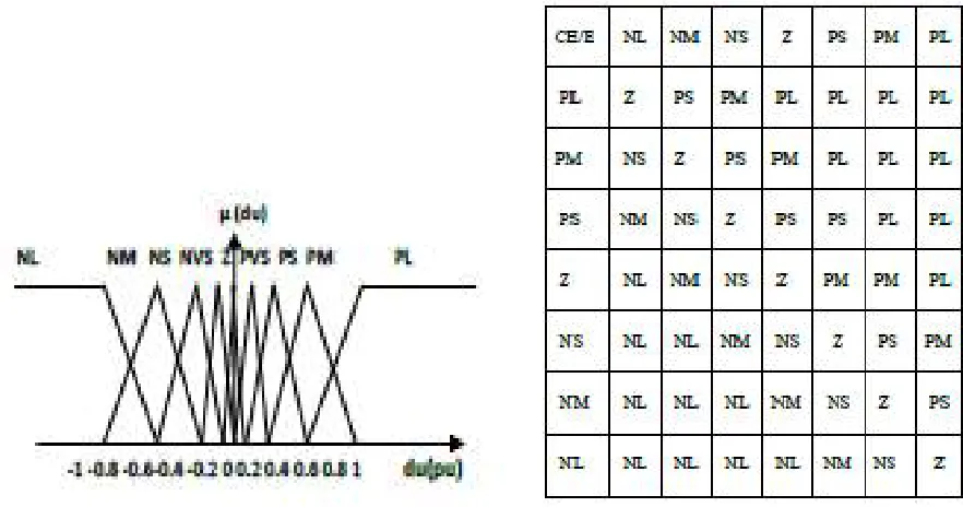
The MRAC method based on reactive power and stator d-axis voltage are combined together with a weighting factor which is generated by a fuzzy controller. The weighting factor ensures the dominant use of reactive power method in low speed high torque region whereas the d – axis voltage method is dominant in high speed low torque region (Gilberto C.D. Sousa et al.1993). A second fuzzy controller tunes the slip gain based on combined detuning error and its slope so as to ensure fast convergence at any operating point on torque-speed plane. The rule base matrix for the fuzzy logic controller generating detuning factor (Kf) is given in Table 2: It clearly shows that if speed is low (L) and torque is high (H) then weighting factor is high(H).
The reference model output is compared with that of adaptive model and the resulting error generates the estimated slip gain through a fuzzy controller. The objective is to provide an adaptive feedback control for fast convergence at any operating point, irrespective of the strength of error signal E and its derivative signal.
From the de-qe model of IM, the stator equations are
= + (ψqs) + ψds --- (4.1.1)
= + (ψds) − ψqs --- (4.1.2)
At steady state condition under vector control,
(ψqs) = 0 --- (4.1.3)
(ψds) = 0 --- (4.1.4)
Ψds = Ls ids --- (4.1.5)
Ψds = Ls ids- = − --- (4.1.6)
= Ls ids --- (4.1.7)
=− − --- (4.1.8)
∗= ids − (reference) --- (4.1.9)
= − (actual) --- (4.1.10)
= − (actual) --- (4.1.11)
∗= ∗ − ∗
where cosθe and sinθe are the unit vector components. The loop errors are divided by the respective scaling factor to derive the per unit variable ΔQ and the ΔVds for manipulation by fuzzy controller. Fuzzy controller generates the
corrective incremental slip gain ΔKs based on the combined detuning error E and its derivative CE as shown in figures
4.1 and 4.2. Membership function for output variable is shown in figure 4.3.
Fig 4.1 Membership function for error Fig 4.2 Membership function for change in error
Table 2. Rule base matrix for weighting factor (kf)
V. SIMULATION RESULTS
The performance of indirect vector control induction motor drive has been simulated in MATLAB environment using simulink.
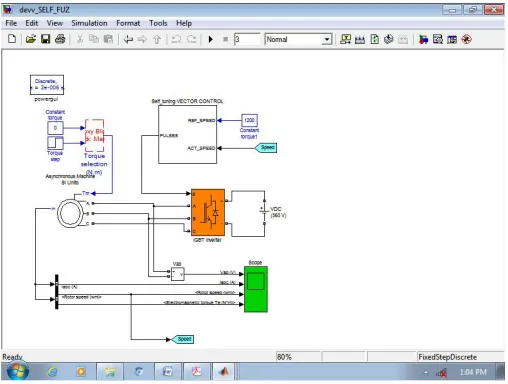
5.1 Simulation Model of Indirect Vector Control
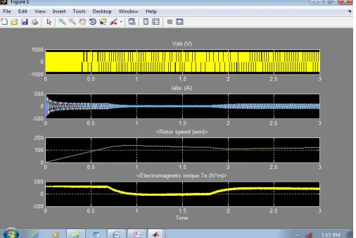
The model for indirect vector control induction motor drive is shown in the Figures below. The induction motor output results with fuzzy based MRAC controller and Fuzzy based sliding mode controller are obtained using simulation and are analyzed in Table.3. The results are shown in below figures5.2 and 5.4
Fig 5.2 Simulation results with Fuzzy based MRAC controller
Fig 5. 3. Simulation Model for Indirect Vector Control with Fuzzy based SMC controller
Controller
Rise Time
(sec)
Settling
Time
(sec)
Peak overshoot
(%)
Fuzzy based SMC
0.07
0.17
4.3
Fuzzy based MRAC
0.05
0.15
3.8
Table.3 Summary of Results
VI. CONCLUSION
In this paper, the fuzzy based MRAC and fuzzy based sliding mode control of vector controlled induction motor drive are proposed and the performances are analyzed. From simulation results it was shown that the proposed the fuzzy based MRAC Controller is robust to external variations and has given satisfactory performances in speed response with no overshoot, rapid time response error and a good tracking reference speed. The decoupling between the stator flux and the torque (speed) is maintained with regard to the application of external load disturbance. The fuzzy based MRAC has shown superior performance than that of fuzzy based sliding mode control. The results obtained from simulation shows that the fuzzy based MRAC Controller has increased dynamic response and superior performance.
REFERENCES
[1] Casadei, D., Profumo, F., Serra, G., Tani, A.; “FOC and DTC: Two Viable Schemes for Induction Motor Torque Control”. IEEE Transactions in Power Electronics, Vol. 17, No. 5, pp 779-787,Sep 2002.
[2] Yen-Shin Lai, “Machine modeling and universal controller for vector Controlled Induction Motor drives,” IEEE Transactions on Energy Conversion, vol. 18, No. 5, pp. 23-32, Mar. 2003.
[3] Y. Tang and L. Xu, “Fuzzy logic application for intelligent control of a variable speed drive,” IEEE Trans. Energy Convers., vol. 9, no. 4, pp. 679– 685, Dec. 1994. [4] C.M. Lin and C.F. Hsu, “Adaptive fuzzy sliding mode control for induction servomotor systems,” IEEE Trans.Energy Convers., Vol.19, No. 2, 2004, pp. 362-368. [5] J.E. Slotine and W.P. Li, ‘Applied Nonlinear Control’(Prentice Hall, 1991).
[6] F. F. Cheng and S. N. Yeh, “Application of fuzzy logic in the speed control of AC servo system and an intelligent inverter,” IEEE Trans. Energy Convers., vol. 8, no. 2, pp. 312–318, Jun. 1993.
[7] C.Y. Su and Y. Stepanenko, “Adaptive control of a class of nonlinear systems with fuzzy logic,” IEEE Trans. Fuzzy Syst., Vol.2, 1994, , pp.285-294. [8] B. Yoo and W. Ham, “Adaptive fuzzy sliding mode control of nonlinear system,” IEEE Trans. Fuzzy Syst., Vol.6, 1998,pp.315-321.
[9] J. Wang, A.B. Rad, and P.T. Chan, “Indirect adaptive fuzzy sliding mode control: Part I-Fuzzy Switching,” Fuzzy Sets and Systems, Vol. 122, No 1, 2001, pp. 21-30.
[10] L.X. Wang, “Stable adaptive fuzzy control of nonlinear systems,” IEEE Trans. Fuzzy Syst., Vol.1, 1993, pp.146-155.
[11] G.W. Chang, G. Espinosa-Perez, E. Mendes, and R. Ortega, “Tuning rulesfor the PI gains of field-oriented controllers of induction motors,” IEEE Trans. Ind. Electron., vol. 47, no. 3, pp. 592–602, Jun. 2000.
[12] M. N. Uddin, T. S. Radwan, and M. A. Rahman, “Performances of fuzzy-logic-based indirect vector control for induction motor drive,” IEEE Trans. Ind. Appl., vol. 38, no. 5, pp. 1219–1225, Sep./Oct. 2002.
[13] E. C. Shin, T. S. Park, W. H. Oh, and J. Y. Yoo, “A design method of PI controller for an induction motor with parameter variation,” in Proc. IEEE IECON, 2003, vol. 1, pp. 408–413.
BIOGRAPHY
L. Sagar received his B.E Degree in 2000 and M.Tech (PE) from VIT, Vellore in 2005.He is working as Associate Professor in EEE Dept., Sreenivasa Institute of Technology and Management Studies(SITAMS) ,Chittoor .He is pursuing Ph.D in Electrical Engineering from JNTUA, Anatapur. His research interests are in the areas of Power Electronics & Drives, AI Techniques to Solid state drives.