Effect of Process Parameters on Resistance Spot
Welding - A Review
Jeevan A. Karande
1, Dr. K. H. Inamdar
21
PG Student,
2Associate Professor, Department of Mechanical Engineering,
Walchand College of Engineering, Sangli, (India)
ABSTRACT
In automobile and aerospace industries resistance welding process is most commonly used for joining sheet
metal. For the fabrication of sheet metal assemblies resistance welding used. Around 6000-8000 spot welds are
required in any car, which shows the level importance of the resistance spot welding. It is a complicated
process, as it involves interactions of the mechanical, thermal, electrical and metallurgical phenomenon.
Resistance welding methods are inexpensive and efficient which has made them highly popular in the making of
sheet joints. Various types of resistance welding are developed for producing continuous and pressure tight
joints on overlapped materials. Controlling the welding parameters plays an important role in the quality of the
weld. This paper reviews on various effects of process parameters on response variables. Input parameters such
as welding current, weld time, electrode force and electrode geometry effects on the response variables such as
tensile strength, hardness, nugget size. ANOVA and Taguchi have been most efficient and powerful tool for
optimization of resistance welding response parameters which produce high-quality parts rapidly and low cost.
Keywords:
electrode force, spot welding, weld quality, welding current, welding time.
I. INTRODUCTION
Resistance spot welding (RSW) is one of the oldest processes used to join sheet metal parts using series of spot
welds. This process is enormously used in mass production of vehicles, metal furniture, and appliances.
Automotive manufacturing uses about 6000 – 8000 spot welds for a vehicle body. As automotive body need to
sustain various types of loading therefor a large number of spot welds are required for an automotive. Due to
this the manufacturing cost for the spot welding process has increased tremendously. Along with this industries
are facing the quality related problem. Quality of Spot weld categorized in terms of the weld strength and spot
weld nugget diameter. Strict quality control leads to improve the quality of each spot weld also reduces the
number of spot welds required for an automotive which leads to reducing the cost significantly. Proper control
of the three main parameters i. e. current, time and force governs the weld quality. Control of these parameters
will generate the required heat for melting the metal and development of spot weld nugget. Major advantages of
resistance welding are it can easily automate. It is high-speed welding, Suitable for high rate production, low
1.1 Resistance spot welding process
Resistance spot welding (RSW) process in which fusion of metal is produced at the faying surface by the heat
generated at the joint because of the contact resistance to the flow of electric current. By applying pressure on
the electrode materials to be joined are brought together. High electric current passes through the electrode and
workpieces hold between the electrodes. Due to contact resistance and Joule heating localized heat generated a
molten weld nugget is formed in the workpieces. Current, time and resistance between the workpiece control the
amount of heat produced. It is desirable to have the maximum temperature at the interface of the parts to be
joined. Therefore, the resistance of the workpieces and the contact resistance between the electrodes and work
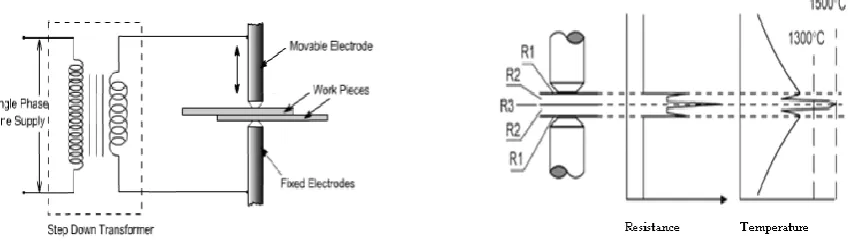
should be kept as low as possible with respect to the resistance between the faying surfaces. [3] The principle of
operation is as shown in Fig. 1.
Fig. 1: Working of resistance spot welding
Fig. 2: Resistance and Temp. Distribution
Curve
As the name indicates, it uses the resistance of the materials to the flow of current that causes localized heating
between the parts to be joined. Excessive heat in the electrodes reduces the electrode cap life and deteriorates
the weld quality. Hence, the electrodes are cooled via water circulation through channels opened inside them.
The temperature and resistance obtained during resistance spot welding operation are as shown in Fig. 2. Where
R1, R2, R3 are the resistances at the Electrode tip and plate surface, Resistance of joining plates, Resistance at
the interface of two plates respectively.
II. HEAT GENERATION
Heating phenomenon plays important role in heat generation in resistance welding. The heat generated depends
upon the current, the time the current is passed and the resistance at the interface. The resistance is a function of
the resistivity and surface condition of the parent material, the size, shape, and material of the electrodes and the
pressure applied by the electrodes.
Q= I2 Rt …….. (Eq. 1)
where I is the current passing through the metal combination, R is the resistance of the base metals and the
contact interfaces, and t is the duration/time of the current flow.
The amount of resistance at the interface of the workpiece depends on the heat transfer capabilities of the
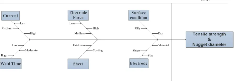
III. PROCESS PARAMETERS
The spot welding process parameters have their own importance. These parameters will determine the quality of
the welds. The appropriate combination of the spot welding parameter will produce strong joining and good
quality of welding. Spot welding parameters include welding current, welding time, electrode force, electrode
diameter and geometry. Various parameters which directly and indirectly control the weld quality are shown in
Fig. 3
Fig.3. Cause and Effect diagram
3.1 Welding current
Welding current is the most effective parameter that controls the heating at the joint of the sheet interface and
hence the weld nugget development and formation takes place. Root penetration and diameter of the weld
increases by the increase in current. It also increases the strength of the weld. Excess current overheat the base
metal which causes molten metal expulsion, it gives rise to excessive indentation, burning of the weld nugget
area and weld cracking.
3.2 Welding time
Weld time is the time during which welding current is applied to the metal sheets.As given in the eq. 1, amount
of The total heat developed is proportional to weld time. Weld time includes squeeze time, weld time, hold time
and off time. In spot welding process at some current density minimum time is required to reach melting
temperature. If sufficient welding current is not used, then increasing the welding time alone will not produce a
weld. When the welding current is high enough, the size of the weld nugget increases with increasing welding
time. If welding time is more, the expulsion of the workpiece will occur or in the worst cases, the electrode may
stick to the workpiece.
3.3 Electrode force
Electrode force is the force exerted by the electrodes onto the workpiece during welding cycle. The purpose of
the electrode force is to squeeze the parts to be weld and the primary purpose is to hold the parts to ensure the
parts in intimate contact at the joining interface. The pressure exerted by the electrode tips on the workpiece has
a great effect on the amount of current that flows through the welding joint. When the electrode force is
heat generation and the size of weld nugget. If the welding force is too low, expulsion may occur immediately
after starting the welding current because of the contact resistance is too high, resulting in rapid heat generation.
This means that the higher electrode force requires a higher weld current. In other words, when the pressure
increases, the electrical current, and subsequent heat are transfer to a wider area, the penetration and area of the
weld will reduce
3.4 Electrode geometry and dimension
As the geometry and dimensions of the electrodes and Workpiece influence the current density distribution they
are also affected the weld quality. The geometry of electrodes in spot welding controls the current density which
results in the size of the weld nugget. Different thicknesses of metal sheets need different welding currents and
other process parameter settings. One general criterion of resistance spot welding is that the weld shall have a
nugget diameter of 5×t1/2, “t” being the thickness of the steel sheet. According to the 5 × t1/2 rules. The diameter
of the electrode contact surface should be slightly larger than the nugget diameter.
IV. LITERATURE SURVEY
A literature survey has been done for analyzing the process parameters and their effect on the response variables
of the resistance welding.
Vignesh et al. [1] studied the effect of various control parameters like electrode tip diameter, welding current,
and heating cycle on the nugget size and tensile shear strength of dissimilar metal spot welding of 2-mm thick
AISI 316L austenitic stainless steel and 2205 Duplex Stainless Steel Sheets. To conduct the experimental spot
welding trials on the dissimilar materials Taguchi orthogonal array (OA) design is selected. The results reveal
that to achieve highest tensile strength with superior weld quality welding current is the most dictating factor.
Yuan et al. [2] Studied welding current, welding time, and electrode force effect on the DP 600 of 1.6 mm
thickness and DC540 of 1 mm thickness. When these 3 parameters increased, the tensile-shear strength of the
welded spot experienced two stages of a notable increase and a subsequent decrease. Plug failure took place
along the plastic deformed DC540 dominated by abnormally grown grains discovered from the interface of
HAZ/BM through electron back-scattered diffraction.
Kang et al. [3] studied the load-controlled fatigue behavior of dissimilar aluminum alloy spot welds made of
2mm thick AA575 wrought sheet and 3mm thick Aural2 die casting sheet with and without the addition of
adhesive prior to welding. While using adhesive in resistance spot weldingto get a large nugget size electrode
and the current schedule was applied to both welding conditions. The results show that at the edge of the nugget
the main fatigue crack initiates and penetrates through the Aural2 die casting sheet in the thickness direction.
Li et.al [4] studied resistance spot welding of commercial pure titanium and aluminium alloy 6061-T6 is carried
out. The microstructure and tensile shear properties of the weld joints are studied. There is a critical range of
welding current at which the reaction between liquid aluminium and solid titanium changes to a reaction
between liquid aluminium and liquid titanium. The welding current has the largest influence upon the tensile
shear properties of the Al/Ti weld joint, while the welding time has a small effect and the electrode force has
Esme [5] conducted experiments under varying electrode forces, welding currents, electrode diameters, and
welding times. The material used was SAE 1010 and welding parameters were set and determined by using the
Taguchi experimental design method. It proved that current and electrode force are the most dominant process
parameters in case of tensile strength of spot weld whereas electrode diameter and welding time were less
effective factors. For controlling the tensile shear strength the results showed that welding current was about two
times more important than the electrode force.
Thakur et al. [6] investigated Taguchi method for spot welding of galvanized steel. ANOVA and S/N ratio was
the analysis techniques used. Welding current, time, electrode diameter and electrode force were the process
parameters. ANOVA showed current (68.93%), welding time (18.66%) and electrode force (8.57%) were most
influencing factors.
Sahota et al. [7] carried the experiment to study the significance of the process parameters i.e. current, electrode
force and weld cycles on resistance spot weld of austenitic SS 316 material, on the percentage improvement in
material hardness. They found that an increase in weld current, weld time and electrode force results in an
increase in weld nugget diameter and width. Electrode indentation also increases by the increase in current, weld
time and electrode force.
Kianersi et al. [8] studied resistance spot welding joints of AISI 316L austenitic stainless steel sheets. Effect of
welding current at constant welding time was considered on the weld properties such as weld nugget size,
tensile–shear load bearing capacity of welded materials, failure modes, failure energy, ductility, and
microstructure of weld nuggets. Result obtained as tensile strength increases up to a certain limit of current
value and then decreases. In weld nugget region, grains were found to be elongated with a columnar structure,
parallel to the electrode compression. Microhardness studies showed that hardness of weld nugget was lower in
comparison to HAZ and base metal.
Ma and Murakawa [9] researched on spot welding of austenitic stainless steel type 304. The relationship of
nugget diameter and hardness distribution and the welding current was investigated. They found out that large
nugget diameter formed by increasing welding current and hardness distribution does not affect by welding
current.
Sung et al. [10] derived analytical stress intensity factor solutions for similar and dissimilar spot welds in lap
-shear specimens underpinned and clamped loading conditions. Finite element analyses are also employed to
obtain the stress intensity factor solutions for similar and dissimilar spot welds in lap-shear specimens
underpinned and clamped loading conditions. Both computational and analytical solutions indicate that the
clamped loading reduces the stress intensity factor solutions for the given specimen geometries by up to 7% for
similar welds and by about 20% for dissimilar magnesium/steel welds.
Rawal and Inamdar [11] studied various optimization techniques are discussed and the use of the Taguchi
method to determine the optimum process parameters is reported. This is because the Taguchi method is a
systematic application of design and analysis of experiments for the purpose of designing and improving
experimental design method. The level of importance of the welding parameters on the tensile shear strength is
determined by using analysis of variance (ANOVA).
V. CONCLUSIONS
This paper has presented an overview of the effect of resistance welding process parameters on the response
variables like tensile strength, nugget width. It is highly efficient welding method that is particularly well suited
for automated production lines and mass production.
i. The resistance welding process highly dependent on the process parameters viz. welding current,
welding time, electrode force, electrode geometry and dimension.
ii. Welding current has a significant effect on the response variable than other parameters. Electrode
force, welding time, are least influencing process parameters.
iii. Materials which are difficult to weld like aluminium also weld by resistance welding.
iv. Increase in welding current increases the tensile strength of weld and also increases nugget size.
v. ANOVA and Taguchi have been very effective tools for parametric optimization of the effect of the
process parameters on response variables such as tensile strength, nugget width.
vi. Process modeling of resistance welding can be done with Finite element analysis tool and ANSYS
software.
REFERENCES
[1.] K. Vignesh, A. Perumal and P. Velmurugan, Optimization of resistance spot welding process parameters
and microstructural examination for dissimilar welding of AISI 316L austenitic stainless steel and 2205
duplex stainless steel, International Journal Advance Manufacturing Technology, 92, 2017, 1-11
[2.] X. Yuana, C. Lia, J. Chena, X. Lia, X. Lianga and X. Pan, Resistance spot welding of dissimilar DP600
and DC54D steels, Journal of Materials Processing Technology, 239, 2017, 31-41.
[3.] J. Kang, Y. Chen, D. Sigler, B. Carlson and D. Wilkinson, Fatigue Behavior of Dissimilar Aluminum
Alloy Spot Welds , 1st International Conference on Structural Integrity, 114, 2015, 149-156.
[4.] Y. Li, Y. Zhang and Z. Luo, Microstructure and mechanical properties of Al/Ti joints welded by
resistance spot welding, Science and Technology of Welding and Joining, 20(5), 2015, 385-394.
[5.] U. Esme, Application of Taguchi method for the optimization of resistance spot welding Process, The
Arabian Journal for Science and Engineering, 34(2B), 2009, 519-528.
[6.] A. Thakur, T. Rao, M. Mukhedkar and V. Nandedkar, Application of Taguchi method for resistance spot
welding of galvanized steel, ARPN Journal of Engineering and Applied Sciences, 5(11), 2010, 22-26.
[7.] D. Sahota, R. Singh, R. Sharma and H. Singh, Study of effect of parameters on resistance spot weld of
SS316 material, Mechanica Confab, 2(2), 2013, 67-78.
[8.] D. Kianersi, A. Mostafaei and A. Amadeh. Resistance spot welding joints of AISI 316L austenitic
stainless steel sheets: Phase transformations, mechanical properties and microstructure characterizations,
[9.] N. Ma and H. Murakawa, Numerical and experimental study on nugget formation in resistance spot
welding for three pieces of high strength steel sheets, Journal of Materials Processing Technology, 210,
2010, 2045–2052.
[10.] S. Sung, J. Chen and J. Pan, Stress Intensity Factor Solutions for Similar and Dissimilar Spot Welds in
Lap-Shear Specimens under Clamped Loading Conditions, Journal of Engineering Fracture Mechanics,
179, 2017, 328-347.
[11.] M. Rawal and K. Inamdar, Review on Various Optimization Techniques used for Process Parameters of
Resistance Spot Welding, International Journal of Current Engineering and Technology, 2014, 160-164.
[12.] M. Alizadeh-Sh and S. Marashi, Resistance spot welding of dissimilar austenitic duplex stainless steels:
Microstructural evolution and failure mode analysis, Journal of Manufacturing Processes, 28, 2017,
186-196.
[13.] K. Zhou and L. Cai, Study on effect of electrode force on resistance spot welding process, Journal of