5 | P a g e
A STUDY ON ANALYSIS AND DESIGN OF GRAVITY DAM
IN FINITE ELEMENT METHOD BY USING STAAD PRO
D Kajavali
1, P Suneetha
21* M.Tech Student, Newton’s Institute of Science & Technology, India
2* Assistant Professor, Newton’s Institute of Science & Technology, India
ABSTRACT
3D modeling and analysis of gravity dam of solid element using STAAD.Pro. The load and load combinations
are taken as per IS 6512. Modelling of dam is considered in two categories, first is without openings and
second is with openings (i.e. galleries). Result of stresses and stress contours are described at the end of paper.
The objective of paper is to have a direction of analysis of dam considering solid elements using STAAD.Pro.
Keywords: Staad.Pro IS 6512, 3D Modeling
INTRODUCTION
It is important to note that, it is not just sufficient to design a strong dam structure, but it is equally important to check the foundation as well for structural integrity. For concrete dams, the stress developed at the junction of the base becomes quite high, which the foundation has to resist. Usually concrete gravity dams are constructed across a river by excavating away the loose overburden till firm rock is encountered which is considered as the actual foundation. Nevertheless not all rocks are of the same quality; they vary with different geological materials and the process by which they have been formed over the years. For example, the hills of the Himalayan range of the mountains are considered geologically young, as well as weaker than the massif of the Deccan plateau. The quality of foundation not only affects the design, it also guides the type of dam that would be suited at a design site. Hence, discussions on the ground foundation aspects have been introduced in this lesson as well
It may also be realized that designing a dam based on field data (like the geometry of the river valley, the foundation allowable bearing capacity .etc) is not the only part that a water resource engineer has to do. He has to get it constructed at the design site which may easily take anywhere between 5 to 10 years or even more depending on the complexity of the work and the volume and type of the structure. It may easily be appreciated that constructing a massive structure across a flowing river is no easy task. In fact tackling of the monsoon flows during the years of construction is a difficult engineering task.
Concrete gravity dam and apparent structures
Basic layout
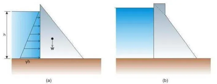
FIGURE 1: Concrete gravity dam section (a)Basic triangular shape(b)Modified shape
The increasing width of the section towards the base is logical since the water pressure also increases linearly with depth as shown in Figure 1a. In the figure, h is assumed as the depth of water and γh is the pressure at base, where γ is the unit weight of water (9810 N/m³), W is the weight of the dam body. The top portion of the dam (Figure 1b) is widened to provide space for vehicle movement. A gravity dam should also have an appropriate spillway for releasing excess flood water of the river during monsoon months. This section looks slightly different from the other non-overflowing sections.
Design of concrete gravity Dam sections
Design of gravity dam
Fundamentally a gravity dam should satisfy the following criteria:
1.
It shall be safe against overturning at any horizontal position within the dam at the contact with the foundation or within the foundation.2.
It should be safe against sliding at any horizontal plane within the dam, at the contact with the foundationor along any geological feature within the foundation.
3.
The section should be so proportional that the allowable stresses in both the concrete and the foundationshould not exceed. Safety of the dam structure is to be checked against possible loadings, which may be classified as primary, secondary or exceptional. The classification is made in terms of the applicability and/or for the relative importance of the load.
i.
Primary loads are identified as universally applicable and of prime importance of the load.ii.
Secondary loads are generally discretionary and of lesser magnitude like sediment load or thermal stresses due to mass concreting.iii.
Exceptional loads are designed on the basis of limited general applicability or having lowprobability of occurrence like inertial loads associated with seismic activity.
7 | P a g e
moment caused by the water impounded in the reservoir behind it. It transfers the loads to the foundations by cantilever action and hence good foundations are pre requisite for the gravity dam.The forces that give stability to the dam include:
1.
Weight of the dam2.
Thrust of the tail waterThe forces that try to destabilize the dam include:
1.
Reservoir water pressure2.
Uplift3.
Forces due to waves in the reservoir4.
Ice pressure5.
Temperature stresses6.
Silt pressure7.
Seismic forces8.
Wind pressureThe forces to be resisted by a gravity dam fall into two categories as given below:
1.
Forces, such as weight of the dam and water pressure which are directly calculated from the unit weight of materials and properties of fluid pressure and2.
Forces such as uplift, earthquake loads ,silt pressure and ice pressure which are assumed only on thebasis of assumptions of varying degree of reliability. In fact to evaluate this category of forces, special care has to be taken and reliance placed on available data, experience
Preparation of foundation for dam construction
A concrete gravity dam intended to be constructed across a river valley would usually be laid on the hard rock foundation below the normal river overburden which consists of sand, loose rocks and boulders. however at any foundation level the hard rock foundation, again, may not always be completely satisfactory all along the proposed foundation and abutment area, since locally there may be cracks and joints, some of these (called seams) being filed with poor quality crushed rock. Hence before the concreting takes place the entire foundation area is checked and in most cases strengthened artificially such that it is able to sustain the loads that would be imposed by the dam and the reservoir water, and the effect of water seeping into the foundations under pressure from the reservoir.
cutoff necessary to ensure a acceptable hydraulic gradient after the reservoir is filled. An example of this type of treatment for Bhakra dam is shown in below Figure.
Improvement of the foundation for a dam may be effected by the following major ways:
1.
Excavation of seams of decayed or weak rock by tunneling and backfilling with concrete.2.
Excavation of weak rock zones by mining methods from shafts sunk to the zone and backfilling the entireexcavated region with concrete.
3.
Excavation for and making a subterranean concrete cutoff walls across leakage channels in the dam foundation where the where the water channels are too large or too wet for mining or grouting4.
Grouting the foundation to increase its strength and to render it impervious.Grouting of the foundation of the dam to consolidate the entire foundation rock and consequently increasing its bearing strength is done by a method that is referred to as consolidation grouting. This is a low pressure grouting for which shallow holes are drilled through the foundation rock in a grid pattern. These holes are drilled to a depth ranging from 3 to 6 m. Prior to the commencement of the grouting operation, the holes are thoroughly washed with alternate use of water and compressed air to remove all.
Temperature control of mass concrete for dams
9 | P a g e
the release of heat of hydration by the concrete. A rapid rise in the temperature of mass concrete takes place during the phase when the concrete mass is in plastic stage and undergoes hardening. After hardening, the concrete gradually cools due to effect of atmospheric temperature, which tends to subject the concrete to high tensile stresses. Cracking occurs in the concrete when these tensile stresses exceed the tensile strength of the concrete. This cracking is undesirable as it affects the water tightness, durability and appearance of hydraulic structures. Hence is prescribed in the Bureau of Indian Standard code IS: 14591-1999 “Temperature control of mass concrete for dams – guidelines”, some of which are given below.Measurement of Water Level on Upstream and Downstream Side
This measurement is useful for calculating the water pressure on the upstream face and downstream face of the dam.
A typical set of piezometer installations for an embankment dam is shown in Figure
Typical installation of piezometers in embankment dams
DESIGN PROCEDURE & RESULTS AND DISSCUSTIONS
Design of Gravity Dam Loads on concrete dams
exceptional loads.
Primary Loads
Water Load
Hydrostatic distribution of pressure with horizontal resultant force P 1
Vertical component of load will also exist in the case of an upstream face batter Hydrostatic distribution of
pressure with horizontal resultantforce P 1
Vertical component of load will also exist in the case of an upstream face batter
Seepage
loads/uplift
11 | P a g e
h2
h1
Uplift pressure distribution for perfectly tight cutoffwall
Value of area reduction factor
Suggested by
0.25 to 0.40
Henry
1.00
Maurice Levy
CONCLUSION
From the modelling and analysis the results can be concluded as per the following points:
Maximum stress in dam with openings is 4193.257 KN/m2 and without openings it is 3117.744 KN/m2. The dam without openings the maximum stresses are concentrating near u/s face ranges from 0.59 N/mm2 to 0.977 N/mm2. Dam with openings, Maximum stress concentrated around the openings are 4.13 N/mm2. So far earthquake forces static loading is given as per the STAAD.Pro definitions and command and not manually, however dynamic analysis is not considered in this paper. There are some uncertainties still revailing regarding stability at support conditions. In this paper Solid foundations are considered to avoid this situation.
REFERENCE
[1]
Karuna Moy Ghosh,”Analysis and Design Practice of Hydraulic Concrete Structure” PHI LearningPrivate Limited
[2]
US Army Corps of Engineers, “ Gravity Dam Design” EM 1110-2-2200 30 June 199513 | P a g e
[4]
IS 12966 (Part 1) -1992, “Practice for Galleries and Other Openings in Dam, Bureau of Indian Standards, New Delhi.[5]
IS 12966 (Part 2) -1990, “Practice for Galleries and Other Openings in Dam, Bureau of IndianStandards, New Delhi.