Copyright 1999, Lucent Technologies All Rights Reserved
Printed in USA
Notice. While reasonable efforts were made to ensure that the information in this book was complete and accurate at the time of printing, Lucent Technologies can assume no responsibility for any errors. Changes and corrections to the information contained in this document may be incorporated into future reissues.
Your Responsibility for Your System’s Security. Toll fraud is the unauthorized use of your
telecommunications system by an unauthorized party, for example, persons other than your company’s employees, agents, subcontractors, or persons working on your company’s behalf. Note that there may be a risk of toll fraud associated with your telecommunications system and, if toll fraud occurs, it can result in substantial additional charges for your telecommunications services. You and your system manager are responsible for the security of your system, such as programming and configuring your equipment to prevent unauthorized use. The system manager is also responsible for reading all installation, instruction, and system administration documents provided with this product in order to fully understand the features that can introduce risk of toll fraud and the steps that can be taken to reduce that risk. Lucent Technologies does not warrant that this product is immune from or will prevent unauthorized use of common-carrier telecommunication services or facilities accessed through or connected to it. Lucent Technologies will not be responsible for any charges that result from such unauthorized use.
Lucent Technologies Fraud Intervention. If you suspect that you are being victimized by toll fraud and you need technical support or assistance and are within the United States, call the Technical Service Center Toll Fraud Intervention Hotline at 1 800 643-2353. If you need technical support or assistance and are outside of the United States, contact the International Technical Assistance Center (ITAC) at US code 303 804-3777. Warranty. Lucent Technologies provides a limited warranty on this product. Refer to the “Limited Use Software License Agreement” card provided with your package.
Trademarks. DEFINITY, PassageWay , and CallMaster are registered trademarks of Lucent Technologies. Prologix is a trademark of Lucent Technologies. Microsoft, MS-DOS, and Microsoft Access are registered trademarks of Microsoft Corporation. Windows and Windows NT are trademarks of Microsoft Corporation. Pentium is a registered trademark of Intel Corporation.
PhoneLine is a registered trademark of CCOM Information Systems. MDAccess and
MasterDirectory are trademarks of CCOM
Information Systems. MDAccess™ is copyrighted by CCOM Information Systems. All rights reserved.
Federal Communication Commission (FCC) Statement: Part 15: Class A Statement. This equipment has been tested and found to comply with the limits for a Class A digital device, pursuant to Part 15 of the FCC Rules. These limits are designed to provide reasonable protection against harmful interference when the equipment is operated in a commercial environment. This equipment generates, uses, and can radiate radio frequency energy and, if not installed and used in accordance with the instruction manual, may cause harmful interference to radio communications. Operation of this equipment in a residential area is likely to cause harmful interference, in which case the user will be required to correct the interference at his own expense.
1 Installation
1-1
Before You Begin 1-1
n Contents of the Package 1-1
n Hardware and Software Requirements for the Personal
Computer 1-1
n Additional Hardware Required 1-2
Installation 1-4
n Administering PC Console, at the Switch, as an Attendant
Console 1-4
n Assessing Your Hardware Components 1-6
n Connecting the PC to the Telephone 1-8
n Connecting the PC/Telephone Configuration to the Power
Source 1-14
n Installing the PC Console Software 1-18
n Administering the PC Console Software 1-20
n Administering the PhoneLine MasterDirectory Software 1-23
n Confirming the Operation of Your Telephone 1-24
2 Understanding PC Console
2-1
Welcome 2-1
An Overview of PC Console 2-1
n Sharing Information within PC Console 2-2
n Personalizing Screens in PC Console 2-2
n Navigating through the PC Console Screens 2-2
n Help Information 2-3
n Busy Lamp Field 2-3
n Feature Buttons 2-3
Display Buttons 2-4
n PC Directories 2-4
3 Console Administration
3-1
Overview 3-1
Accessing the Console Administration Area 3-2 Assigning Attendant Profiles and Passwords 3-2 Identifying Button Functions 3-4
Defining System Parameters 3-11
Creating Custom Languages 3-16
Exiting the Console Administration Area 3-22
4 Directory Administration
4-1
Overview 4-1
Using the PhoneLine MasterDirectory Software 4-1 Helpful Hints When Building Your Directories 4-2 Importing an Upload File — A Quick Overview 4-4
5 Console Operations
5-1
Operations Overview 5-1
Accessing and Exiting PC Console Operations 5-2
Call Handling 5-3
n Answering a Call 5-3
n Conferencing Multiple Parties Together on a Call 5-5
n Holding a Call 5-7
n Placing a Call 5-8
n Releasing a Call 5-12
n Splitting a Call 5-12
n Transferring (Extending) a Call 5-13
n Typing Notes About a Call 5-19
Searching and Updating a Directory 5-20
n Accessing the PC Console Directory Functions 5-20
n Searching for Information in a PC Console Directory 5-21
n Placing a Call from a PC Console Directory 5-21
n Changing the Information in a PC Console Directory 5-22
6 Switch Features
6-1
Abbreviated Dialing 6-1
Attendant Call Waiting 6-2
Attendant Conference 6-3
Attendant Control of Trunk Group Access 6-3 Attendant Direct Trunk Group Selection 6-4 Attendant Intrusion (Call Offer) (Generic 3r) 6-5
n Interactions 6-5
Attendant Lockout 6-6
Attendant Override of Diversion Features (Generic 3r) 6-6 Attendant Priority Queue (Generic 3r) 6-7
Attendant Recall 6-8
Attendant Serial Call (Generic 3r) 6-9
Auto Hold (Generic 3r) 6-10
Auto Start and Don’t Split (Generic 3r) 6-10
n Interactions 6-12
Automatic Alternate Routing and Automatic Route
Selection 6-12
Automatic Answer 6-12
Automatic Circuit Assurance 6-12 Busy Verification of Telephones and Trunks 6-13
Call Coverage 6-13
n Consult 6-15
n Coverage Callback 6-16
Call Detail Recording (CDR) Account Code Dialing 6-16
Call Forwarding All Calls 6-17
Call Park 6-19
Code Calling Access 6-20
Controlled Restrictions 6-22
Emergency Access to the Attendant 6-24
Individual Attendant Access 6-26
Integrated Directory 6-27
Inter-PBX Attendant Service (IAS) 6-28
n Interactions 6-28
ISDN-PRI 6-30
n Basic ISDN-PRI Call 6-31
n Redirected ISDN-PRI Call 6-32
Leave Word Calling 6-32
Loudspeaker Paging Access 6-34
Loudspeaker Paging Access-Deluxe 6-35
Message Retrieval 6-39
Multiple Listed Directory Numbers 6-40
Network Access-Private 6-41
Network Access-Public 6-41
Night Service 6-41
n Night Service Disconnect Timer 6-42
Serial Call (Generic 3r) 6-42
Straightforward Outward Completion 6-43
Through Dialing 6-43
Time-of-Day Routing 6-43
n Clocked Manual Override Option 6-43
n Immediate Manual Override Option 6-45
Timing 6-46
n Alerting Timer (Generic 3) 6-46
n No Answer Timer (Generic 3) 6-47
n Return Call Timeout 6-47
n Timed Reminder 6-48
Trunk Group Busy/Warning Indicators to Attendant 6-49
Trunk Identification 6-49
7 Operating in a Distributed Communications System
Environment
7-1
Attendant Call Waiting 7-1
Attendant Control of Trunk Group Access 7-1
Attendant Display 7-2
Automatic Circuit Assurance 7-2 Busy Verification of Telephones and Trunks 7-2
Call Forwarding All Calls 7-3
Direct Trunk Group Selection 7-3 Trunk Group Busy/Warning Indicators 7-3
8 Operating in a Centralized Attendant Service
Environment
8-1
An Overview of the CAS Environment 8-1
n Tones Associated with CAS Calls 8-2
n Call Bar Display Information 8-3
Operating Procedures 8-4
CAS Backup Service 8-8
9 Troubleshooting
9-1
Backup Procedures and Considerations 9-1 Troubleshooting PC Console Installation and Usage
Problems 9-2
n Troubleshooting Problems with the Telephone or
PassageWay Adapter 9-3
n Troubleshooting Error Messages 9-5
n Troubleshooting General Usage Problems 9-14
Troubleshooting Switch Problems 9-20
n Console Alarm Indicators 9-20
n Alarm and Alarm Reported Indicators 9-20
n Optional Alarm Lamps 9-20
n The Features You Can Use to Troubleshoot Problems at the
Switch 9-21
Automatic Circuit Assurance (ACA) 9-22
Busy Verification of Telephones and Trunks 9-22 DCS Busy Verification of Telephones and Remote Trunks 9-26 Trunk Group Busy/Warning Indicators to Attendant 9-31
Trunk Identification 9-31
The Contents of This Document
This user’s manual contains all of the procedures and reference material you may need to install, administer, operate, maintain, and troubleshoot PC Console Release 2 in your unique environment.
n Chapter 1, “Installation,” describes the components included with PC Console, outlines hardware/software requirements and configuration options, and provides step-by-step procedures to successfully install PC Console.
n Chapter 2, “Understanding PC Console,” provides an overview of PC Console functions, and describes its individual features.
n Chapter 3, “Console Administration,” provides an overview and step-by-step instructions to administer PC Console. This includes identifying approved users, defining their logins, passwords, and preferences (including the interface language), and labeling the buttons that are displayed on the PC Console screen.
n Chapter 4, “Directory Administration,” describes how PC Console uses the database information you create via the PhoneLine® MasterDirectory™ software.
n Chapter 5, “Console Operations,” contains an overview of PC Console operations, and the procedures most frequently used by the operator. Here you will find the instructions to answer, place, hold, split, transfer, conference, and release calls. Also refer here for instructions to search for any person listed in a PC Console directory.
n Chapter 6, “Switch Features,” describes the switch features most commonly used by the PC Console operator. These features are presented alphabetically.
n Chapter 7, “Operating in a Distributed Communications System
Environment,” describes the Distributed Communications System (DCS) features that can operate transparently in your environment. A DCS configuration consists of 2 to 20 private switches that are interconnected. These switches may be in different geographical locations. To certain system features, however, the DCS configuration appears as a single switch. These features, and their usage, are listed alphabetically in this chapter.
n Chapter 9, “Troubleshooting,” contains procedures and techniques for troubleshooting hardware- and software-related problems. This chapter also provides emergency recovery information, and outlines the
preventative steps you can take to ensure the integrity of your system.
n The Quick Reference Card contains summaries of the commands and procedures you will use most frequently in the PC Console environment. A glossary is provided at the rear of this guide.
How to Comment on This Document
To comment on this document, please return the comment card.
Conventions Used in This Manual
The following conventions are used in this manual:
n The mouse or the keyboard can be used to accomplish most tasks in PC Console. Whenever possible, procedures apply to both the mouse and the keyboard.
n Information in bold type characters, such as F8, represents a keyboard option, button, or indicator on the PC Console screen.
n A keyboard equivalent is an alternative method of making a selection. Pressing ALT and the underlined character of a selection allows you to make that selection. For example, pressing ALT-T from the PC Console Operations screen allows you to select the Attendant drop down menu.
Security Issues
As a Lucent Technologies customer, you should be aware that there is an increasing problem of telephone fraud. Telephone toll fraud can occur in many forms, despite the numerous efforts of telephone companies and telephone equipment manufacturers to control it. Some individuals use electronic devices to prevent or falsify records of these calls. Others charge calls to someone else’s number by illegally using lost or stolen calling cards, billing innocent parties, clipping onto someone else’s line, or breaking into someone else’s telephone equipment physically or electronically.
Today security problems are not just limited to toll fraud. There have been sharp increases in reported incidents of hackers: criminals skilled in
Maintenance ports are their most recent target of abuse. In this scenario, hackers find a private branch exchange (PBX) maintenance port number with their “war dialer;” a device that randomly dials telephone numbers until a modem or dial tone is obtained. They then “hack” the user ID and password, sometimes just by using the PBX default passwords, to enter your system.
This is the most dangerous type of abuse because, once in your system, the hackers have control over all the administrative commands. While in your system, they have been known to:
n Turn on Remote Access or Direct Inward System Access (DISA). Hackers
have been known to change the system at 8:00 p.m. to allow fraudulent calls. Then, at 3:00 a.m., they reprogram the system back to its original
configuration. One company was hit three weekends in a row before it realized what was happening.
n Turn off Call Detail Recording (CDR) or Station Message Detail Recording
(SMDR), hack your system all weekend, then turn it back on before Monday morning. This is especially disturbing to managers who are security
conscious and check the CDR/SMDR reports every morning looking for suspicious activity. They will not see records of the calls because
CDR/SMDR was turned off by the hackers. The administrator may notice the absence of CDR/SMDR records for evening, night, and weekend calls made by employees.
PBX Security Measures
Everyone in your company who uses the telephone system is responsible for system security. Users and attendants need to be aware of how to recognize and react to potential hacker activity. Informed people are more likely to cooperate with security measures that often make the system less flexible and more difficult to use.
Implement the following general security measures to protect your PBX and discourage the unauthorized use of your communications system.
n Never program passwords or authorization codes onto auto-dial buttons.
Display phones reveal the programmed numbers, and internal abusers can use the auto-dial buttons to originate unauthorized calls.
n Discourage the practice of writing down passwords. If a password needs to
be written down, keep it in a secure place and never discard it while it is active.
n Attendants should tell their system manager if they answer a series of calls
where there is silence on the other end or the caller hangs up.
n Advise users with special telephone privileges (such as Remote Access,
voice mail outcalling, and call forwarding off-switch) of the potential risks and responsibilities.
n Be suspicious of any caller who claims to be with the telephone company and
wants to check an outside line. Ask for a callback number, hang up, and confirm the caller’s identity.
n Never distribute the office telephone directory to anyone outside the
company; be careful when discarding it.
n Never accept collect phone calls.
n Never discuss your telephone system’s numbering plan with anyone outside
the company.
n Change passwords frequently (at least quarterly). Set password expiration
times and tell users when the changes go into effect. Changing passwords routinely on a specific date (such as the first of the month) helps users to remember to do so.
n Establish well-controlled procedures for resetting passwords.
n Limit the number of invalid attempts to access voice mail to five or less. n Monitor access to the dial-up maintenance port. Change the access
password regularly and issue it only to authorized personnel. Consider using the Remote Port Security Device (RPSD) — a Lucent Technologies product that helps protect your administration and maintenance ports from
unauthorized access.
n Create a PBX system management policy concerning employee turnover and include these actions:
Delete all unused voice mailboxes in the voice mail system.
If an employee is terminated, immediately delete any voice mailboxes belonging to that employee.
If a terminated employee had Remote Access calling privileges and a personal authorization code, remove the authorization code
immediately.
If barrier codes and/or authorization codes were shared by the terminated employee, these should be changed immediately. Notify the remaining users as well.
If the terminated employee had access to the system administration interface, their login ID should be removed (G3V3 or later). Any associated passwords should be changed immediately.
n Back up system files regularly to ensure a timely recovery should it be
required. Schedule regular, off-site backups.
n Keep the attendant console(s) and supporting documentation in an office that
n Keep telephone wiring closets and equipment rooms locked.
n Keep telephone logs and printed reports in locations that only authorized
personnel can enter.
n Design distributed reports so they do not reveal password or trunk access
code information.
For additional information about securing against toll fraud, refer to the following document:
Document # Document Title
555-025-600 BCS Products Security Handbook
Lucent Technologies Fraud
Intervention
If you suspect you are being victimized by toll fraud and you need technical support or assistance, call Technical Service Center Toll Fraud Intervention Hotline at 1 800 643-2353.
Related Documentation
The document you are reading now assumes that you are already familiar with your computer, with MS-DOS®, and with Microsoft® Windows®. If this is not the case, refer to the following documentation to learn this necessary information, then continue with your PC Console training:
n User’s guide for your personal computer. You may need this reference for explanations of commands used by your PC when you install, configure, and use your PC Console software package.
n User’s guide for Microsoft MS-DOS. You may need this reference for
explanations of the DOS commands used by your PC during the operation of your PC Console software package.
n User’s guide for Microsoft Windows. You may need this reference for
Product Support
PC Console was designed for compatibility with all current versions of DEFINITY Communications System G1 and G3, and DEFINITY Prologix Solutions.
If you have a question about PC Console, first read this manual or refer to the on-line help. If you cannot find the answer, contact the Technical Service Center (TSC) at 1 800 242-2121.
1
Before You Begin
Before you begin to install PC Console, verify that your PC Console
installation package is complete, and that your PC meets both the hardware and software requirements identified in this section.
Contents of the Package
Your PC Console package should contain the following:
n PC Console software
One CD-ROM that contains the PC Console installation and application software, on-line help and PC Console documentation.
n Registration card for notification of updates
If you want to be notified of updates to the PC Console system, return this registration card (by mail or fax) to the BCS Publications Center. The appropriate address is provided on the card.
n Comment card
Lucent Technologies welcomes your feedback on the PC Console documentation. Please return the comment card (by mail or fax) to the address provided on the card.
Hardware and Software Requirements for the Personal Computer
n 15” Super VGA (SVGA) monitor
n Pentium®-based processor
n 100 Megahertz clocking speed
n 16 MB of RAM available to PC Console
n CD-ROM drive
n Microsoft Windows NT™, Microsoft Windows 95, or Microsoft Windows 3.1 or later
n A COM Port dedicated to PC Console. (No other application may vie for this port.)
n Sufficient hard disk space. You will need 4 MB of hard disk space for the PC Console software, plus additional space for your PC Console directory information. The space for your PC Console directory information depends upon the number of users you are supporting and the amount of information stored for each person. Refer to the
following chart to roughly assess the additional space required.
Number of Usersè
Number of Characters per User’s Record ê
200 500 1,000 5,000 10,000 20,000
200 4 MB 4.1 MB 4.2 MB 4.5 MB 5 MB 6 MB
500 4.1 MB 4.3 MB 4.5 MB 6.5 MB 9 MB 14 MB
1,000 4.2 MB 4.5 MB 5 MB 9 MB 14 MB 24 MB
5,000 4.5 MB 6.5 MB 9 MB 29 MB 54 MB 104 MB
10,000 5 MB 9 MB 14 MB 54 MB 104 MB 204 MB
20,000 6 MB 14 MB 54 MB 104 MB 204 MB 404 MB
Additional Hardware Required
In addition to a personal computer that meets or exceeds the requirements listed above, you will need the following hardware components to install and use your PC Console.
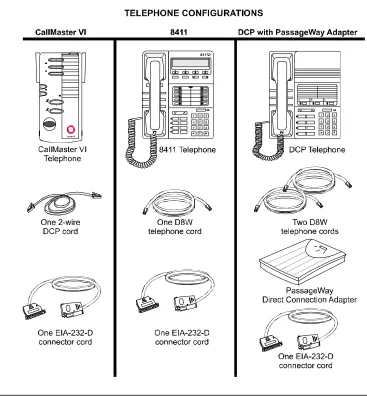
n Telephone; a 2- or 4-wire DCP telephone
a CallMaster® VI telephone, and associated 2-wire DCP cord
or
an 8411 telephone, and associated D8W telephone cord
a 64xx-, 74xx-, 84xx-, or 94xx-series DCP telephone, and associated D8W telephone cord; plus the DEFINITY PassageWay®
DirectConnect Adapter, with D8W telephone cord.
NOTE:
You may want to augment your telephone configuration with a headset and necessary adapter to facilitate ease-of-use.
n PC Connector cord:
Verify that the EIA-232-D Connector cord provided with PC Console is appropriate for connecting your PC to either the PassageWay Adapter (if one is used) or to the telephone.
One end of the cord connects to the COM port on your PC. The COM port typically has either a 9-pin male, or a 25-pin male interface.
The other end of the cord connects either to the PassageWay Adapter (which has a 9-pin female interface), or to the telephone (which has a 25-pin female interface).
The EIA-232-D Connector cord must connect to each of the two devices in your environment. If necessary, you can purchase adapters to change one or both ends of the cord to a different number of pins, or to a different gender.
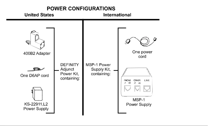
n Power supply:
For US installations, the DEFINITY Power Kit, containing:
KS-22911 power supply, 400B2 adapter, and D6AP cord.
For US or International installations, the MSP-1 Power Supply Kit, containing: MSP-1 power supply, and power cord.
NOTE:
Installation
Installing PC Console is a multi-step process. You must perform each of the following, in the order indicated:
n Administer PC Console, at the switch, as an Attendant Console. n Assess your hardware components.
n Connect the PC to the telephone.
n Connect the PC/telephone configuration to the power source.
NOTE:
This step is not necessary if you are using a CallMaster VI telephone. The CallMaster VI is powered by the switch, and does not require a separate power supply.
n Install the PC Console software. n Administer the PC Console software.
n If appropriate, administer the PhoneLine MasterDirectory software. n Confirm that your telephone is operating as an Attendant Console.
Each of these steps is outlined, in order, in this chapter. To begin, proceed to the next section, “Administering PC Console, at the Switch, as an Attendant Console.”
Administering PC Console, at the Switch, as an Attendant Console
The first step in the installation process is administering the console, at the switch. It is essential that the switch recognize PC Console as a 302 Attendant Console
To administer PC Console, at the Switch, as a 302 Attendant Console:
1. Enter the following command:
display console parameters
2. Verify that the switch console parameters are correct. These should include (but are not limited to) Class of Service, Class of Restriction, timing, and queue priorities.
3. If PC Console is replacing an existing 302 Attendant Console, print a copy of the associated attendant form using the following
command:
4. If PC Console is not replacing an existing 302 Attendant Console, use the following command to enter the data for PC Console as a 302 Attendant Console:
add attendant #
5. Select the appropriate options on the attendant form. Among these options is the type of console being defined. We recommend that you specify a 302B to achieve the greatest compatibility with PC Console.
6. Make a note of the feature button assignments, particularly those that have been moved from their default positions (indicated in the “Default Button Number” column, below).
Default Button Number
Button Assignment
1 Split
6 Hold
19 Forced Release
23 Night Service
24 Position Busy
7. Make a note of the display button assignments, particularly those that have been moved from their default positions (indicated in the “Default Button Number” column, below). While these display buttons are not required, they are strongly recommended if you wish to achieve the greatest functionality in PC Console.
Default Button Number
Button Assignment
1 Normal
4 Next
6 Call-Disp
8. Assign an extension to this station, if desired.
9. Print the attendant form using the following command. (You will need the information it contains when administering PC Console.)
Assessing Your Hardware Components
PC Console can be configured to use either a 64xx-, 74xx-, 84xx- or 94xx-series DCP telephone with PassageWay Adapter, or an 8411 or CallMaster VI telephone. You will note that the 8411 and the CallMaster VI telephones do not require the PassageWay Adapter. The functionality of these telephones eliminates the need for this additional component.
In addition, the PC Console telephone can be powered by one of two
components. The KS-22911 power supply can be used in the United States, and the MSP-1 can be used in most international installations.
NOTE:
The CallMaster VI is powered by the switch and does not require a separate power supply.
Connecting the PC to the Telephone
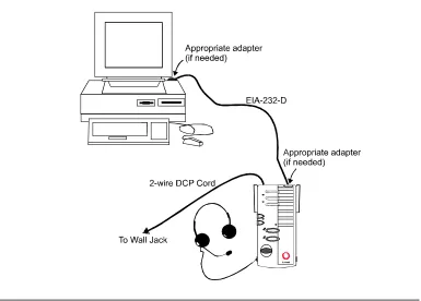
If you are using a CallMaster VI telephone (see Figure 1-3):
1. Plug the EIA-232-D Connector cord (including adapter, if
necessary) into the communications (COM) port on the PC. If more than one port is available, write down the number of the port to which you physically attach the cord. Tighten all retaining screws.
NOTE:
Attach an adapter only if the EIA-232-D Connector cord does not conform to the COM port on the PC. You can purchase adapters to change the number of pins and/or the gender of the connector.
2. Plug the remaining end of the EIA-232-D Connector cord (including adapter, if necessary) into the 9-pin interface at the top of the telephone. Tighten all retaining screws.
NOTE:
Attach an adapter only if the EIA-232-D Connector cord does not conform to the 9-pin female interface on the telephone. You can purchase adapters to change the number of pins and/or the gender of the connector.
3. Connect one end of the 2-wire DCP cord to the jack at the top of the telephone.
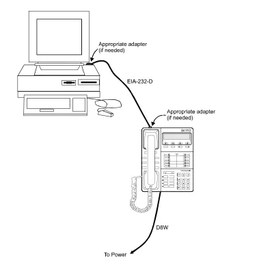
If you are using an 8411 telephone (see Figure 1-4):
1. Plug the EIA-232-D Connector cord (including adapter, if
necessary) into the communications (COM) port on the PC. If more than one port is available, write down the number of the port to which you physically attach the cord. Tighten all retaining screws.
NOTE:
Attach an adapter only if the EIA-232-D Connector cord does not conform to the COM port on the PC. You can purchase adapters to change the number of pins and/or the gender of the connector.
2. Plug the remaining end of the EIA-232-D Connector cord (including adapter, if necessary) into the 25-pin interface on the bottom of the telephone. Tighten all retaining screws.
NOTE:
Attach an adapter only if the EIA-232-D Connector cord does not conform to the 25-pin female interface on the telephone. You can purchase adapters to change the number of pins and/or the gender of the connector.
3. Connect one end of a D8W cord to the jack on the bottom of the 8411 telephone. You will use the remaining end of this cord to connect to the power source.
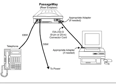
If you are using a DCP telephone and PassageWay Adapter (see Figure 1-5):
1. Plug the EIA-232-D Connector cord (including adapter, if
necessary) into the communications (COM) port on the PC. If more than one port is available, write down the number of the port to which you physically attach the cord. Tighten all retaining screws.
NOTE:
Attach an adapter only if the EIA-232-D Connector cord does not conform to the COM port on the PC. You can purchase adapters to change the number of pins and/or the gender of the connector.
2. Plug the remaining end of the EIA-232-D Connector cord (including adapter, if necessary) into the 9-pin interface on the PassageWay Adapter. Tighten all retaining screws.
NOTE:
Attach an adapter only if the EIA-232-D Connector cord does not conform to the 9-pin female interface on the PassageWay Adapter. You can purchase adapters to change the number of pins and/or the gender of the connector.
3. Connect one end of a D8W cord to the “Phone” jack on the PassageWay Adapter. Connect the other end to the jack on the DCP telephone.
4. Connect one end of another D8W cord to the “Line” jack on the PassageWay Adapter. You will use the remaining end of this cord to connect to the power source. Turn to the section entitled
Connecting the PC/Telephone Configuration to the Power Source
If you are using an 8411, 64xx-, 74xx-, 84xx-, or 94xx-series telephone, you must connect the PC/Telephone configuration to a separate power source.
NOTE:
This step is not necessary if you are using a CallMaster VI telephone. The CallMaster VI is powered by the switch, and does not require a separate power supply.
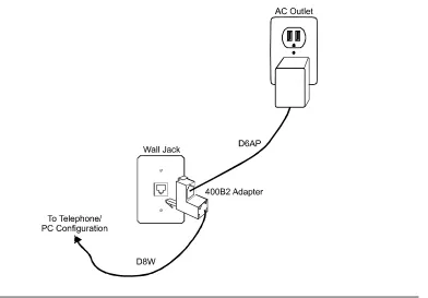
If you are using a KS-22911,L2 power source (see Figure 1-6):
1. Plug the 4002B2 Adapter into the PBX wall jack.
2. Plug the remaining end of the D8W cord (from the PC/Telephone configuration you assembled earlier) into the bottom connector on the 400B2 adapter.
3. Plug one end of the D6AP cord into the power supply unit.
4. Plug the other end of the D6AP cord into the top connector on the 400B2 adapter.
5. Plug the power supply unit into a 120 VAC, 60 Hz outlet.
NOTE:
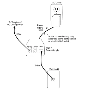
If you are using an MSP-1 power source (see Figure 1-7):
1. Plug the remaining end of the D8W cord (from the PC/Telephone configuration you assembled earlier) into the connector labeled “Phone” on the power supply.
2. Insert one end of the second D8W cord into the connector labeled “Line” on the power supply.
3. Insert the remaining end of the second D8W cord into the PBX wall jack.
4. Plug the power supply cord into the power supply unit.
5. Plug the other end of the power supply cord into an appropriate AC outlet. If the power supply cord provided with the MSP-1 Power Supply is not compatible with your AC outlet, you may either:
n use an adapter to conform to local blade arrangement, or
n use a replacement cord if an appropriate adapter is not available.
NOTE:
Installing the PC Console Software
To install the PC Console software:
1. Insert the PC Console CD in the CD-ROM drive. (The instructions in this section assume that you are using drive d. If this is not the case, substitute d with the appropriate drive letter.)
2. Access your Desktop or the Program Manager screen. 3. Select Start-Run or File-Run.
n The Run dialog box is displayed. 4. Type d:setup
5. Click OK.
n The Welcome screen is displayed. 6. Click Next.
n The Select Destination Directory dialog box is displayed. 7. If you want to install the PC Console software to a directory other
than the indicated default, or you want to install it onto a LAN server, select that location now.
NOTE:
The PC Console database files can be installed on your network to allow file sharing with other console operators. If you select this type of installation, also install and maintain a local copy of the database information on the hard drive of each PC that may require access to this information. In the event of a LAN failure, PC Console will switch to the local copy of the database information that allows it to place and receive phone calls.
NOTE:
If you are upgrading or reinstalling the PC Console software, you will see a message later indicating that the directory already exists. You can safely reinstall to the same directory. The PC Console installation program will automatically create a backup directory of the previously installed software, in a location that you can specify.
8. If the destination directory you are about to select does not yet exist, skip to Step 13.
9. Click Next.
n The Backup Replaced Files dialog box is displayed.
If you do not want to retain a copy of your previously installed PC Console files, click No and skip to Step 12. Otherwise, click
Yes. 10. Click Next.
n The SelectBackup Directory dialog box is displayed.
11. Select the directory into which the old PC Console files should be placed.
12. If you are using Windows 95 or Windows NT 4.x, skip to Step 15. 13. Click Next.
n The Select Program Manager Group dialog box is displayed. 14. If you want your PC Console icons to reside in a program group
other than the indicated default, select that program group now. 15. Click Next.
n The Select Communication Port dialog box is displayed. 16. Use the cursor keys or mouse to indicate which COMPort (on the
PC) you will use to physically connect the PC to the telephone or PassageWay Adapter.
17. Click Next.
n The Ready To Install dialog box is displayed. 18. Click Next.
n The installation process begins. It takes approximately four to five minutes to install the contents of the CD-ROM to your computer.
n When the process is complete, the Installation Completed
dialog box is displayed. 19. Click Finish.
n If you are using Windows NT or Windows 95 and any system files were updated during the installation process, the Restart Computer dialog box is displayed. Click OK to restart your computer.
Administering the PC Console Software
Once the software is installed you can successfully administer PC Console.
n If you have performed an upgrade from a previous version of
PC Console, you must administer several new capabilities of PC Console.
n If this is a new installation, you will need to administer PC Console.
Essentially, this involves launching and naming your PC Console system, creating attendant profiles, identifying button functions, and assigning the appropriate system parameters.
To administer the PC Console software following a product upgrade:
1. Access your Desktop or the Program Manager screen. 2. Double-click on the Console Administration icon.
n The PC Console splash screen is displayed, followed by the PC Console Login window.
3. Enter a new system name, and type a new password to be associated with that system.
NOTE:
Although you named your system prior to this upgrade, you must rename it now. In the next few steps, you will restore all of the information previously saved in the old version of PC Console.
4. Click OK or press ENTER.
n The PC Console Login window is redisplayed, and the screen prompts you to reenter the identical password. (This is done for verification purposes.)
6. Click OK or press ENTER.
n The New Password Confirmed dialog box is displayed. 7. Click OK or press ENTER.
8. Select Administration-Upgrade-Administration from the Menu Bar.
n The software attempts to locate the System Database last used by PC Console. It looks for a file named pccon.mdb in the pccon\admin directory.
If it is able to locate the pccon.mdb file, it copies the old information to the new System Database, with the exception of any records that would create duplicate entries in your new database.
If the software cannot locate the pccon.mdb file, a dialog box is displayed asking you to identify the old System Database. Locate and select the appropriate pccon.mdb file; then click OK or press ENTER. PC Console copies the old information to the new System Database, with the exception of any records that would create duplicate entries in your new database.
n When the System Database has been successfully upgraded, a confirmation message is displayed at the bottom of the screen.
If your version of PC Console includes any custom languages,
continue to the next step.
If your version of PC Console does not include any custom languages, skip to Step 11.
9. Select Administration-Upgrade-Language from the Menu Bar.
n The software attempts to locate the Language Database last used by PC Console. It looks for a file named pcclang.mdb in the pccon\admin directory.
If it is able to locate the pcclang.mdb file, it copies the old information to the new Language Database, with the exception of any records that would create duplicate entries in your new database.
n When the Language Database has been successfully upgraded, a confirmation message is displayed at the bottom of the screen. 10. For each custom language already defined in your PC Console
environment, locate and translate the new terms that will appear within the PC Console screens. (Refer, if necessary to the section “Creating Custom Languages” in Chapter 3, “Console
Administration.”) You must complete this translation process before your custom language can be used.
11. Label the PC Console display buttons to match the display buttons administered at the switch for the Attendant Console. (Refer, if necessary to the section “Identifying Button Functions” in Chapter 3, “Console Administration.”)
12. Select Administration-Upgrade-Directory from the Menu Bar.
n The software attempts to locate the Directory Database last used by PC Console. It looks for a file named dir.mdb in the
pccon\direc directory.
If it is able to locate the dir.mdb file, it copies the old information to the new System Database.
If the software cannot locate the dir.mdb file, a dialog box is displayed asking you to identify the old Directory Database. Locate and select the appropriate dir.mdb file; then click OK
or press ENTER. PC Console copies the old information to the new Directory Database.
n When the Directory Database has been successfully upgraded, a confirmation message is displayed at the bottom of the screen. 13. Select Administration-Exit from the Menu Bar.
14. Turn to Chapter 3, “Console Administration,” and follow the step-by-step procedures required to finish turning up your PC Console system. Specifically, you must verify that your attendant profiles are correct, that the button function assignments are correct, and that the appropriate system parameters has been defined. You may also need to complete any partially-created custom languages so they may be used in your environment.
To administer the PC Console software for a new installation:
1. Access your Desktop or the Program Manager screen. 2. Double-click on the Console Administration icon.
3. Enter a new system name, and type a new password to be associated with that system.
NOTE:
You must name your system the first time you access the PC Console application. If necessary, you can change this name later, from within the PC Console software.
You will need to know the password, that you are assigning now, whenever you make administrative changes to the PC Console application. You can also use this password to launch the PC Console Operations application.
4. Click OK or press ENTER.
n The PC Console Login window is redisplayed, and the screen prompts you to reenter the identical password. (This is done for verification purposes.)
5. Type the password again, exactly as you typed it before. 6. Click OK or press ENTER.
n The New Password Confirmed dialog box is displayed. 7. Click OK or press ENTER.
8. Select Administration-Exit from the Menu Bar.
9. Turn to Chapter 3, “Console Administration,” and follow the step-by-step procedures required to finish turning up your PC Console system. Specifically, you need to create your attendant profiles, identify the button functions in PC Console, and assign the appropriate system parameters. You can also create custom languages, if any are required in your environment.
Administering the PhoneLine MasterDirectory Software
Once the software is installed on your PC, you will need to use the PhoneLine MasterDirectory portion to build the various directories that contain
information about the people in your environment.
To administer the PhoneLine MasterDirectory software:
1. Read Chapter 4, “Directory Administration,” of this document. This short chapter provides a brief overview of the relationship between PC Console and the PhoneLine MasterDirectory software.
2. Once you have read Chapter 4, refer to the PhoneLine
MasterDirectory User’s Guide for the step-by-step instructions to build your directories. You can create up to four directories, each containing information about the people in your environment.
Confirming the Operation of Your Telephone
Next, you must verify that your telephone is operating an Attendant Console.
If you are using an 8411 or CallMaster VI telephone:
1. Press the Speaker button on the telephone. Verify that the red LED associated with this button is lighted, and that dial tone is not heard. (This is an indication that PC Console is correctly administered as a 302 Attendant Console.)
NOTE:
The analog jack on the back of the 8411 telephone is inoperable when used with PC Console.
If you are using a DCP telephone and PassageWay Adapter:
1. Verify that the red light is glowing steadily on top of the PassageWay Adapter.
2. Press the Speaker button on the telephone. Verify that the red LED associated with this button is lighted, and that dial tone is not heard. (This is an indication that PC Console is correctly administered as a 302 Attendant Console.)
This completes the installation process for the PC Console system. If you are not already familiar with PC Console, read Chapter 2,
2
Welcome
Congratulations on your purchase of Lucent Technologies’ PC Console — the elegant solution to your call handling needs in a PC environment.
PC Console offers all of the capabilities of a hardware Attendant Console; plus the ability to share information across your organization, personalize your screen displays, and manage your call handling tasks more quickly and efficiently. This chapter provides a quick synopsis of PC Console’s capabilities. It is intended to introduce the new user to basic PC Console concepts, and to introduce new features to the experienced PC Console user.
An Overview of PC Console
PC Console was created to accommodate your attendant’s call handling needs. PC Console allows you to:
n Access and update information that is shared across a Local Area Network
n Personalize the screens that each attendant uses; even creating or modifying
the language of the interface
n Navigate through the call handling areas smoothly n Check the status of any extension in your environment
n Locate any person in your environment by searching through a PC Console
n Place a call directly to a found entry in the PC Console database by clicking
the Call button, or by pressing ENTER
n Immediately access on-line help information Each of these capabilities is discussed in this chapter.
Sharing Information within PC Console
PC Console was designed to share information across your organization. During the installation and administration of PC Console, your administrator creates and “points to” several databases; each containing information that all console operators can share.
Database information can be stored locally, or on a Local Area Network drive. For backup purposes, a database can be co-located; accessed off of the Local Area Network, with an automatic switch to the local hard drive if the network drive becomes unavailable.
Personalizing Screens in PC Console
PC Console allows the administrator to select the language that each user sees on the PC Console screens. The administrator can also modify an existing language set to conform to a local dialect; or, if necessary, create an entirely new interface language.
In addition, the administrator can specify which attendants prefer Help Tip displays, and which attendants want the Auto Transfer capability to complete their transfers automatically. You can override this “profile” information at any time, by changing your preferences during any PC Console session. The changes you make only affect the current session; they do not become a permanent part of your profile.
Navigating through the PC Console Screens
PC Console is partitioned into the following functional areas.
F1 The Help screen information that provides immediate on-line help.
F2 The Busy Lamp Field that identifies, and provides access to, each extension in your environment. You can also click to select a particular Trunk Group or Hundreds Group button.
F3 The feature buttons that allow you to perform the same function as feature buttons on a hardware console.
F4 The PC Directories that allow you to locate and call a person, based upon their entry in a PC Console database.
To get immediate on-line help, press F1. You can find information by subject matter, search by a word or phrase, or jump between related subjects quickly to locate the information you need.
Busy Lamp Field
To move quickly to the Busy Lamp Field area, press F2. This area of the screen turns blue to indicate it is active. From this area, you can:
n Click a Trunk Groupbutton, to access a particular trunk group. The button
turns white to indicate it is active. Now you can follow your normal dialing procedure, using either your keyboard or telephone keypad, to dial the outbound number.
If the Trunk Group button should turn pink, this is a warning signal. It
indicates that the trunk group is operating at 50% of available capacity. If the Trunk Group button turns red, this is a busy signal. It indicates that the trunk group has reached 100% of available capacity.
n Click a numbered Hundreds Groupbutton, to access a group of extensions. All of its administered extensions are displayed. Busy extensions appear in dark blue, and idle extensions appear in light blue. To find out the name of the person at any extension, use your right mouse button to click that extension. A Help Tip box, containing the person’s extension and name, is immediately displayed. To dial the extension, use your left mouse button to click the extension number.
The selected Hundreds Group button is displayed in white. Any other Hundreds Group buttons remain in gray.
Feature Buttons
To move quickly to the Feature Button area, press F3. This area of the screen turns blue to indicate it is active.
The Feature Button area displays the short name assigned to every feature button administered for PC Console. To get a longer description of any feature button, position your cursor over the button. Assuming the administrator has enabled Help Tips, a Help Tip box containing a description of that button is displayed.
If the Position Busy feature button should turn blue, this indicates that all positions are either busy or unavailable.
Five feature buttons are on every PC Console — Split, Hold, Forced Release, Position Busy, and Night Service. Your system administrator can assign the remaining buttons as optional feature buttons; thus giving you access to the various switch features.
Display Buttons
Display buttons may appear when you activate a feature. To look at the Display Button area, click the button labeled Display. The Display Button screen opens, and turns blue to indicate that it is active.
The Display Button area indicates the short name assigned to every display button administered for PC Console. To get a longer description of any display button, position your cursor over the button. Again, if the administrator has enabled Help Tips, a Help Tip box containing a description of that button is displayed.
Display buttons are used in exactly the same manner as display buttons on a telephone or hardware console. Click the button to perform a particular task. For example, if you are using the Integrated Directory feature, clicking the Next
button advances to the next entry in the list. When a button is activated, it turns white. When it is deactivated, it turns gray.
PC Directories
There are several ways to move quickly to the PC Directories area. You can do any of the following:
n Click the icon associated with the desired directory.
n Press and hold the ALT key, then press the number associated with the
desired directory.
n Press F4 to move to the PC Directory area, use the TAB key to select the
desired directory, then press ENTER. The PC Directory screen opens.
PC Console can have up to four directories; each containing information about the people in your environment. This may include each person’s first name, last name, phone number, and other pertinent pieces of information; as well as any notes that you have saved with the person’s record.
You can use this information to locate anyone in your environment — searching for them by any field; or calling them by pressing ENTER or clicking the Call
button.
to locate. As you type, PC Console jumps to the first record that matches the string you have entered thus far. Click to pick the record you want.
To close this window, click its Quit button.
Call Handling Area
To move quickly to the Call Handling area, press F5. This area of the screen turns blue to indicate it is active. From the Call Handling area, you can answer, place, hold, split, transfer, conference, and release calls.
The Call Handling area displays six “call bars,” each providing information about one phone call that you are currently handling.
Starting at the left, each call bar displays:
n An Information icon . You can click this icon at any time to retrieve the
caller identification for that call.
n The call’s hold cycle and holding-time, indicated in minutes and seconds.
n The letter identification assigned to this call appearance. You will recognize
this as the standard call appearance on a hardware console.
n A “notepad” area containing any temporary notes you have entered for this
n Your available options, illustrated graphically, as indicated in the following
table of icons.
Icon What it does The function key that also
accesses this call handling option
Add F6
Answer F6
Call F6
Cancel F7
Conference F9
Forced Release F9
Hold F7
Release F8
Retrieve F7
Transfer F6
To handle a call, or receive additional information about a particular call, click on the call bar associated with that call. The call becomes the “current call,” and its call bar is displayed with a blue border to help you distinguish it at a glance. The Second Party Display, located at the bottom of your screen, shows any
additional information that is available for this call.
For example, when an incoming call arrives, your screen will display information about that call. Specifically, the following will occur:
n You hear ringing.
To answer the incoming call, you click the Answer icon .
n The ringing stops.
n You are connected to the calling party.
n Now you see a Transfer , Hold , Release and
Conference icon on the call bar.
The icons themselves are displayed as needed. If an icon cannot be used on the current call, it is removed from the call bar. This allows you to quickly access all of the appropriate functions, while removing any clutter from the screen.
To hold the call, you click its Hold icon .
n The call is placed on hold.
n The Transfer , Hold , Release and Conference
icons disappear.
n A Retrieve icon is displayed on the call bar.
n The timer on the left side of the call bar keeps track of the call’s hold cycle
and hold time. The hold cycle tells you how many times this call has been placed on hold, and the hold time tells you how long it has been on hold in the current cycle.
n The call bar itself changes to pink. This indicates that the call is on hold. If the call bar were to turn red, this would indicate that the call had been on hold for longer than a preset threshold.
To retrieve the held call, click the Retrieve icon .
n The held call is retrieved.
n The Retrieve icon disappears.
n The Transfer , Hold , Release and Conference
icons are redisplayed on the call bar.
Some applications and components (like voice mail) require that tones be sent, or not sent. However please note that if Auto Start is administered on your switch, you must specify that tones are not sent during dialing. Therefore, you would leave the box unchecked.
The last portion of the screen is the Alarm and Status Panel. It is located in the lower right corner of your screen, and exists strictly to give you feedback information. There may be up to six messages displayed in this area:
n Alarm indicates a system problem has been detected.
n Alarm Reported indicates that the system has alerted the maintenance
organization of the detected problem.
n Calls Waiting indicates that one or more calls are waiting in the general
attendant queue.
n Calls Waiting Warning indicates that the number of calls in the queue has reached a preset threshold.
n Individual Calls Waiting indicates that one or more calls directed to your
personal extension (not the “0” extension) are waiting.
n Position Available indicates that your position is available to receive calls.
All of the procedures you will use for general call handling are outlined, in detail, in Chapter 5, “Console Operations.” If you are a new user, be certain to read all
of Chapter 5 to become proficient as a PC Console attendant. Once you are comfortable with these new procedures, you may prefer the Quick Reference card, as a reminder.
3
Overview
The term “Console Administration” refers to a collection of procedures. These are the procedures that you, as System Administrator, will use to define your environment. This includes identifying the users who are authorized to access the PC Console system, and specifying how the buttons are configured at the switch by configuring them the same way within the PC Console software. In addition, you can decide what language each user will see on the PC Console screens. You can also modify an existing language set to conform to a local dialect; or, if necessary, create an entirely new interface language. The terms that you define will appear on PC Console’s operating screens.
NOTE:
Accessing the Console Administration
Area
To access the console administration area:
1. Close any open PC Console application.
2. From your Desktop or the Program Manager screen, locate the PC Console program group (or the program group containing the PC Console application icons).
3. Double-click on the Console Administration icon.
n The entry window is displayed. 4. Type the system name and password. 5. Click OK or press ENTER.
n The Console Administration screen is displayed.
Assigning Attendant Profiles and
Passwords
The Attendant Management folder allows you to add, change, or delete profile information for yourself, or for any other PC Console attendant.
To add a new attendant:
1. Click the Attendant Management folder. 2. Click Add.
3. Type a login name for the new user and press ENTER.
n The highlighting moves to a button labeled Password. 4. Click ENTER.
5. Type the password that the user will require to gain entry to PC Console, then press ENTER.
6. Re-type the new password (for verification purposes), and again press
ENTER.
7. Select the appropriate responses to each of the following. This profile information will be saved, along with the new user’s name and
password.
Auto Transfer. Check this box if the user wants calls to be transferred automatically; without operator announcement. This feature reduces the number of steps required to transfer a call.
NOTE:
If Auto Transfer is not enabled for a particular attendant, the attendant can temporarily override this instruction by checking a box labeled “Auto Transfer” on the PC Console Operations screen. Checking this box will cause all calls to be
transferred automatically until the box is unchecked again.
Help Tip Visible. Check this box if the user wishes to see the “Help Tips” that provide a short description of the button over which the cursor is positioned.
8. Click Save.
n The new user and his/her profile are added to the list of authorized PC Console attendants.
To delete an existing attendant:
1. Click the Attendant Management folder.
2. Highlight the name of the user that is to be deleted.
NOTE:
It is not possible to delete your system name in the list of users. 3. Click Delete.
n A message box asks for confirmation of this deletion. 4. Click Yes.
n The user’s name and profile are deleted from the list of authorized attendants.
To change the profile for an existing attendant:
3. Make the appropriate changes to the following profile information:
Language. Select an interface language for the user. The language that you specify will determine what the user sees on the PC Console administration and operating screens, as well as prompts, messages, and other information.
Auto Transfer. Check this box if the user wants calls to be transferred automatically; without operator announcement. This feature reduces the number of steps required to transfer a call.
NOTE:
If Auto Transfer is not enabled for a particular attendant, the attendant can temporarily override this instruction by checking a box labeled “Auto Transfer” on the PC Console Operations screen. Checking this box will cause all calls to be
transferred automatically until the box is unchecked again.
Help Tip Visible. Check this box if the user wishes to see the “Help Tips” that provide a short description of the button over which the cursor is currently positioned.
4. Click Save.
n The user’s modified profile is saved.
Identifying Button Functions
Administering the buttons for PC Console is one of the steps required to define your operating environment. Use the following procedures to specify how the buttons are configured at the switch, by configuring them the same way within the PC Console software.
It is important to recognize that this area of PC Console is strictly used to
indicate to the attendant how your switch is configured. If you reconfigure button functions at the switch, you must likewise reconfigure the corresponding
PC Console buttons. Otherwise, the PC Console user will have no way of knowing that the function assigned to the button has changed. Changing the label alone, within PC Console, does not inherently change its function at the switch.
To access the Button Identification area of PC Console:
1. From the Attendant Management folder, click the tab labeled Button Identification.
Trunk Groups
Hundreds Groups, and their associated Busy Lamp Fields
Feature Buttons
Display Buttons
To label the Trunk Group buttons:
1. From the Button Identification area, click the button labeled Trunk Groups.
n Twelve Trunk Groupbuttons, initially unlabeled, are displayed across the screen.
These buttons perform the same function as Trunk Groupbuttons on a non-PC based attendant console. Specifically, they allow the attendant to select an outgoing trunk group. They can also be used to select a code-calling or loudspeaker paging zone.
Each of these buttons must be labeled to identify the trunk group with which it is associated. This is typically accomplished by labeling each Trunk Groupbutton according to the corresponding location. For example, your buttons might be labeled “LA,” “Dallas,” “NY,” and so forth.
2. Label each Trunk Groupbutton, just as it is administered at the switch.
NOTE:
Each button label can hold a maximum of six characters. 3. When you are finished making changes, click Save.
n Your changes are saved.
To label the Hundreds Group buttons and associated Busy Lamp Fields:
1. From the Button Identification area, click the button labeled Hundreds Groups.
n Twenty Hundreds Group buttons, initially unlabeled, are displayed across the screen.
2. Label each Hundreds Groupbutton, just as it has been administered at the switch.
The label you assign to each Hundreds Groupbutton should reflect the first digit (or group of digits) for the associated extensions. For
example:
n If your dialing plan has 3-digit extensions, you could conceivably have 1000 extensions — 000 through 999. You would therefore assign up to 10 Hundreds Groupbuttons at the switch, and
duplicate their assignments here. The firstHundreds Groupbutton would handle extensions 000 through 099. The second would handle extensions 100 through 199, and so forth. The extensions themselves would automatically be labeled within the grid that is displayed to the attendant (000 through 099, and 100 through 199), and the corresponding Hundreds Groupbutton would be labeled with the group’s prefix — in this example, 0 and 1.
n If your dialing plan has 5-digit extensions, and you have 500 extensions — for example 10000 through 10499, you would assign 5 Hundreds Groupbuttons. The firstHundreds Groupbutton would handle extensions 10000 through 10099. The second would handle extensions 10100 through 10199, and so forth. The extensions themselves would automatically be labeled within the grid, and the corresponding Hundreds Groupbutton would be labeled with the group’s prefix — in this example, 100 or 101.
NOTE:
Each button label can hold a maximum of three characters. 3. When you are finished administering the Hundreds Group buttons,
click Save.
n Your changes are saved.
To label the feature buttons:
1. From the Button Identification area, click the button labeled Feature Buttons.
These buttons perform the same function as feature buttons on a non-PC based attendant console. They are used to access and perform pre-determined functions. For example, an Integrated Directory feature button accesses the Integrated Directory feature on the switch.
If a button is labeled with a feature name, the button is
“administered,” and may be used by the attendant. If a button is labeled with a number, the button is not “administered.” It performs no function within PC Console and is not displayed to the attendant.
n The Feature Button Definition Table on the left side of the screen allows you to identify the purpose, label, and relative location of each feature button that is administered for your system.
“Term” is a long description of the button’s function. It may be up to 60 characters in length. This is the description that can be displayed as a Help Tip when the user positions the cursor over the button.
“Label” is the short description that will appear on the button within the PC Console screens. It may be up to 8 characters in length.
“Number” indicates where the button will reside within the two-column table on the right side of the screen. The number 1 indicates the top left position. The number 24 indicates the bottom right position.
The buttons that you administer, label, and position here will appear on the Console Operations screen that is used by the attendant. If an entry in the Feature Button Definition Table appears in red, this indicates that the feature is required for PC Console. You cannot delete this entry. The required feature buttons and their default positions are indicated below:
Default Button Number
Button Assignment
1 Split
6 Hold
19 Forced Release
23 Night Service
If an entry in the Feature Button Definition Table appears in blue, this indicates that the feature is not required for PC Console. If, however, you wish to administer that particular feature button, you must do so utilizing the line that the partially-created button already occupies. For example, if you want to administer an Integrated Directory feature button, you must use the line already labeled “Integrated Directory,” and simply supply the label for the button, and the number that specifies its position within the two-column table.
2. Make any required changes to the feature button labels to synchronize their functions with those already administered for the console at the switch.
n To add a new feature button, click on an empty line within the Feature Button Definition Table. In the left cell, type a long description (up to 60 characters) that will be displayed as the button’s Help Tip. In the center cell, type the short label (up to 8 characters) that will appear on the button. In the right cell, type the position (1 through 24) that this feature button will occupy. You can select from the button positions that have not yet been assigned to other feature buttons.
n To change an existing feature button, click on the cell whose contents are to be changed. Use the standard Windows editing features to position your cursor and edit the field, as appropriate.
n To delete an existing feature button, you must clear the contents of all three cells associated with that button. Beginning with the left-most cell, double-click on the cell to highlight its contents. Press
DELETE. Repeat this procedure until all three associated cells are empty.
NOTE:
If an entry in the Feature Button Definition Table appears in red, this indicates that the feature is required for PC Console. You cannot delete this entry. In addition, you must make certain that the identical feature button assignments have been made on the switch, so that PC Console can communicate successfully with the switch.
A Helpful Hint: Avoid assigning labels that could confuse the attendant. For example, do not use the label “Directory” to describe the Integrated Directory feature button. This could easily be
mistaken for the PC Console Directory function. 3. When you are finished making changes, click Save.
To label the display buttons:
1. From the Button Identification area, click the button labeled Display.
n Eight display buttons are