AT&T System 75
Implementation Manual
Release
1
Version 1
5 5 5 - 2 0 0 - 6 5 0 I s s u e 1 , S e p t e m b e r 1 9 8 5
C o p y r i g h t © 1 9 8 5 A T & T A l l R i g h t s R e s e r v e d
TO ORDER COPIES OF THIS MANUAL
Customer:
Contact: Your Call: AT&T Write: AT&T 2855 P. o.
AT&T Information Systems Account Team on 800-432-6600
Customer Information Center North Franklin Road
Box 19901
Indianapolis, Indiana 46219 AT&T Sales:
Call: 800-526-0735
AT&T Service Division:
Call: Regional Technical Information Resource Manager (TIRM)
Order:
By 9-digit document number stated on title page
Note:
All documents covering System 75 and the Applications Processor (AP 16) are identified
in the Documentation Guide, 999-700-200IS.
Report comments on this document to the “Hot Line” number listed below.
Call: AT&T on 800-334-0404
8 A.M. - 4 P.M. Eastern Time Monday through Friday
This
Implementation
implement the System been completed, using
M a n u a l
provides the feature forms and instructions required to 75. It is intended for use after the communications design process has theAT&T System
75Planning Manual,
555-200-600, and theAT&T
System 75 Configuration Manual, 555-200-630.
This Manual describes the activities of the Communications Survey, gives instructions on how to gather appropriate system/terminal information, and includes the feature forms on which that information is to be compiled. This Manual is divided into five parts.Part 1:
Part 2 :
Part 3:
Part 4:
Part 5:
Network Access
Features–feature forms in this part will always be filled out, for system initialization, by the Account Team. It will be necessary for the AT&T Account Team to work with the customer to obtain unique customer information.C o m m u n i c a t i o n s
Survey-instructions in this part are essential to proper implementation of the System 75. P a r t 2 a l s o i n c l u d e s i n s t r u c t i o n s f o r completing the Port Assignment Record.System
Features–descriptions in this part are accompanied by instructions on how to implement this feature including a list of all relative forms.System
Features—Forms–feature forms in this part may be completed by the customer or the AT&T Account Team.N o n - S t a n d a r d V o i c e T e r m i n a l
Forms-instructions in this part may be completed by the customer or the AT&T Account Team to implement existing voice terminals that are not directly supported by System75
software.Parts 1, 2, 4, and 5, when completed, will be used in conjunction with the
A d m i n i s t r a t i o n
Manual AT&T System 75 System Management, 555-200-500,
to initialize the System 75. A set of blank forms is included in the appendix to be reproduced as necessary. The blank forms should be returned to the manual for later use. The completed forms should be kept as a permanent hard copy.This Manual is to be used during system initialization as well as during ongoing system administration.
This manual replaces Issue 2 of the
AT&T System 75 Implementation Manual Release
1Version
1, 999-700-277IS. Differences between the 555-200-650 and the 999-700-277S include:Reformat
Implementation procedures for non-standard A set of blank forms arranged alphabetically
TABLE OF CONTENTS
PART 1
NETWORK ACCESS FEATURES
INTRODUCTION . . . . NETWORK FEATURES . . . . . AUTOMATIC ROUTE SELECTION . . . . Automatic Route Selection Patterns . . . . Automatic Route Selection Home Numbering Plan Area
(HNPA) . . . . Automatic Route Selection Foreign Numbering Plan Area
(FNPA) . . . . Automatic Route Selection Remote Home Numbering Plan Area
(RHNPA) . . . . Automatic Route Selection Prefix Codes . . . . Automatic Route Selection Toll Table . . . . Feature Access Codes.... . . . RESTRICTION–TOLL/CODE . . . . Allowed Calls List... . . . . Code Restriction HNPA. . . . Code Restriction FNPA. . . . Digit Absorption . . . . NETWORK ACCESS . . . . Network Access—Private . . . . Network Access–Public . . . . TRUNK FORMS . . . .
Page
1-1 1-4 1-4 1-5
1-6
1-8
INTRODUCTION
PART 1
OVERVIEW
In the planning process, system requirements were identified by the AT&T Account Team and the client. Those requirements were converted into orderable system hardware when the Account Team configured the system. Network Access features must now be assigned to the system. The information in Part 1 will then be used to initialize the system. This part is always filled out by the Account Team.
In order to complete this
Implementation Manual,
you must:Ž
Have hardware and feature knowledge (consult theAT&T System 75 Reference
Manual—System Description, 555-200-200,
and theAT&T System 75 Reference
Manual–Feature Description, 555-200-201.)
Ž
Know what system and terminal hardware has been ordered [refer to the Delivery Operations Support System (DOSS) order]HOW TO USE
Part 1 of this Manual provides the feature forms and instructions required to implement Network Access facilities and related optional features. Feature forms provided are accurate representations of the screens that will be displayed on the System Access Terminal (SAT). A complete set of blank forms has been included in the back of the manual. Reproduce these forms as needed to implement the system. It is a good idea to save these forms as a permanent hard copy.
Many of the forms that appear on the SAT contain dynamic fields. Dynamic fields are fields that appear or disappear on the form depending upon how another field is assigned. Dynamic fields are identified on the forms in this manual, so that the user will be aware of them when initializing the system.
The procedural checklist shown below should be followed to complete Part 1. Step 1: Complete trunk forms and optional features forms as required.
ACTIVITY INTERVAL SYSTEM 75 PLANNING PRE-SALE SYSTEM 75 CONFIGURATION PRE-SALE O R D E S R A L P E L A C E D
SYSTEM 75 ACTIVITIES SCHEDULE
SYSTEM MANAGEMENT REVIEW WEEKS* 6-5 CUSTOMER TRAINING WEEK 4 COMMUNICATIONS SURVEY AND IMPLEMENTATION WEEKS 3-2 S Y S T E M D E L I v E R Y .
YOU ARE HERE
* WEEKS BEFORE CUTOVER (ESTIMATED)
NETWORK FEATURES
AUTOMATIC ROUTE SELECTION
Routes calls over the public network based on the preferred (normally the least expensive) route available at the time the call is placed.
Automatic Route Selection (ARS) Software is required to implement this feature. In addition, the following form(s) or sections of a form(s) must be completed:
•
Automatic Route Selection Patterns Form–complete patterns as applicable.Ž
Automatic Route Selection Home Numbering Plan Area Form –complete sections as applicable.Ž
Automatic Route Selection Foreign Numbering Plan Area Form-complete sections as applicable.Ž
Automatic Route Selection Remote Home Numbering Plan Area Form–complete sections as necessary.Ž
Automatic Route Selection Prefix Codes Form–complete all sections.•
Automatic Route Selection Toll Table Form–complete sections as applicable.Ž
Feature Access Codes Form–assign an ARS Access Code.Automatic Route Selection Patterns
Purpose
This form is used to implement up to 16 Routing Patterns. Each pattern can contain up to six alternate routes.
Instructions
Make assignments, as required, for the following fields:
Ž
Pattern Number–enter the pattern number between 1 and 16. Pattern 1 is defaulted for the HNPA Table entry. Patterns 2 through 5 are defaulted for RHNPA Tables 1 through 4, respectively.Ž
Trunk Group–enter the group number between 1 and 50.Ž
FRL–enter the FRL (O to 7) assigned to each trunk group in order of preference.Note: An FRL of “7” is most restrictive; an FRL of “O” is least restrictive.
Page 1 of 1 A R S P A T T E R N
P a t t e r n N u m b e r : 1 P A T T E R N A S S I G N M E N T S ( E n t e r u p t o 6 )
T r u n k F R L T r u n k F R L
G r o u p G r o u p
1: — — 4 : — —
2 : 5 :
— — — —
3 : 6 :
— — — —
Automatic Route Selection Home Numbering Plan Area (HNPA)
Purpose
This form is used to change the 800 office codes and Automatic Route Selection (ARS) patterns.
Note: System 75 recognizes the service codes 411, 611, and 911 as area codes because of the middle digit, 1. Therefore, these codes must be administered in the FNPA table.
Instructions
Make assignments, as required, for the following fields:
Ž
Office Code–enter the Office Code to be accessed via ARS.Ž
ARS Pattern Number–enter a pattern number from 1 to 16. (Default value is 1.)Note: Only office codes with an ARS Pattern Number other than “1” need to be entered because “l” is the default value.
Note: Enter “O” for intercept if not allowed.
Page 1 of 1 A R S H N P A T A B L E E N T R Y F O R M
O f f i c e C o d e : A R S P a t t e r n N u m b e r : —
O f f i c e C o d e : A R S P a t t e r n N u m b e r : —
O f f i c e C o d e : A R S P a t t e r n N u m b e r : —
O f f i c e C o d e : A R S P a t t e r n N u m b e r : —
O f f i c e C o d e : A R S P a t t e r n N u m b e r : —
O f f i c e C o d e : A R S P a t t e r n N u m b e r : _
O f f i c e C o d e : A R S P a t t e r n N u m b e r : _
Automatic Route Selection Foreign Numbering Plan Area (FNPA)
Purpose
This form is used to change FNPAs. Reproduce this form to cover all required entries.
Instructions
Make assignments, as required, for the following fields:
NPA or Service Code–enter the NPA or Service Code that can be accessed via ARS. The NPA codes reside in the System 75.
• ARS Pattern Number or RHNPA Table Number—enter the ARS pattern number from 1 to 16 or the RHNPA Table Number from 1 to 4. An “r” must precede the RHNPA entry to differentiate from ARS patterns 1 to 4. Enter O (for intercept) if calls to the NPA or service code will not be allowed.
f 4 P A o r A R S P a t t e r n N u m b e r o r R H N P A N P A o r A R S P a t t e r n N u m b e r o r R H N P A N P A o r A R S P a t t e r n N u m b e r o r R H N P A N P A o r A R S P a t t e r n N u m b e r o r R H N P A N P A o r A R S P a t t e r n N u m b e r o r R H N P A N P A o r A R S P a t t e r n N u m b e r o r R H N P A N P A o r A R S P a t t e r n N u m b e r o r R H N P A
A R S F N P A T A B L E S e r v i c e C o d e : T a b l e N u m b e r : S e r v i c e C o d e : T a b l e N u m b e r : S e r v i c e C o d e : T a b l e N u m b e r : S e r v i c e C o d e : T a b l e N u m b e r : S e r v i c e C o d e : T a b l e N u m b e r : S e r v i c e C o d e : T a b l e N u m b e r : S e r v i c e C o d e : T a b l e N u m b e r :
Page 1 of 1 E N T R Y
—
—
—
—
—
—
—
Automatic Route Selection Remote Home Numbering Plan Area (RHNPA)
Purpose
This form is used to enter the 800 office codes and the associated ARS Pattern Somber for the four selected RHNPAs. Reproduce this form to cover all required entries.
Instructions
Ž
RHXPA Table Number-enter the applicable table number from 1 to 4. Up to eight forms may be required for each table. (Default value is 1.)Ž
Office Code–enter the desired Office Code. Each of the four RHNPA tables can contain up to 800 possible office codes.Ž
ARS Pattern Number—enter a Pattern Number between 1 and 16. If one pattern will be used most often (that is, accessed by the greatest number of office codes in this block), assign that pattern as choice 1. Otherwise, the correlation between Pattern Choice Numbers and Patterns is completely arbitrary. (Default value is 2.) Enter “O” for intercept if calls to the office code will not be allowed.A R S R H N P A T A B L E E N T R Y
R H N P A T a b l e N u m b e r : _ O f f i c e C o d e : — A R S P a t t e r n N u m b e r : —
R H N P A T a b l e N u m b e r : _ O f f i c e C o d e : — A R S P a t t e r n N u m b e r : —
R H N P A T a b l e N u m b e r : _ O f f i c e C o d e : — A R S P a t t e r n N u m b e r : —
R H N P A T a b l e N u m b e r : — O f f i c e C o d e : — A R S P a t t e r n N u m b e r : —
P a g e I of I
Automatic Route Selection Prefix Codes
Purpose
This form is used to specify the ARS patterns to be used for O, O+, and 011 calls.
Instructions
. Pattern Number For O, O+, 01, or the routing of O-type calls.
. Pattern Number For 10xxx–make
011+ — enter the ARS pattern that will determine
no entry.
o o+ 01 011+
10 XXX
Page 1 of 1 A R S P R E F I X C O D E S
O p e r a t o r A c c e s s O p e r a t o r A s s i s t e d C a l l
I n t e r n a t i o n a l I n t e r n a t i o n a l L o n g D i s t a n c e
P a t t e r n N u m b e r F o r O , 0 + , O P a t t e r n N u m b e r
O p e r a t o r D i r e c t
C a r r i e r D i a l i n g
Automatic Route Selection Toll Table
Purpose
This form is used to assign toll tables required for ARS.
Instructions
Make assignments, as required, for the following fields:
Ž
Toll Table Number–enter the Toll Table Number from 1 to 32. (Default value is n.)Ž
Office Code–enter a 3-digit Office Code.Ž
Toll—enter “n” for each nontoll code. (Default value is “y.”)Page 1 of 1 A R S T O L L T A B L E E N T R Y
T o l l T a b l e N u m b e r : _ O f f i c e C o d e : —
T o l l ? y—
T o l l T a b l e N u m b e r : _ O f f i c e C o d e : —
T o l l ? y—
T o l l T a b l e N u m b e r : — O f f i c e C o d e : — T o l l ? y—
T o l l T a b l e N u m b e r : — O f f i c e C o d e : — T o l l ? y—
L
Feature Access Codes
Purpose
This form is used to implement System 75 Feature Access Codes. These codes are predefine numbers and characters which, when dialed, activate or cancel certain System 75 features. The recommended values have been preprinted. If these values do not meet business requirements, strike through the values and enter the desired codes in the blank space provided beside the default values. All entries must agree with the Dial Plan Record.
Instructions
Ž
Ž
Ž
Ž
Ž
Ž
Ž
In each field that ends with Access Code, enter the digits required to access that feature.
In each field that ends with feature.
In each field that ends with deactivate a feature.
Activation, enter the digits required to
Deactivation, enter the digits required
activate the
to cancel or
In the field labeled Leave Word Calling Message Retrieval Lock, enter the digits required to lock the display module on the voice terminal. (Users cannot retrieve Leave Word Calling Messages on a “locked” module. )
In the field labeled Leave Word Calling Message Retrieval Unlock, enter the digits required before entering another code to unlock the display module.
In the field labeled L e a v e W o r d C a l l i n g S e n d A M e s s a g e , enter the digits required to send a message.
Page 1 of 2 F E A T U R E A C C E S S C O D E ( F A C )
A b b r e v i a t e d D i a l i n g L i s t l A c c e s s C o d e : A b b r e v i a t e d D i a l i n g L i s t 2 A c c e s s C o d e : A b b r e v i a t e d D i a l i n g L i s t 3 A c c e s s C o d e : A n s w e r B a c k A c c e s s C o d e : A u t o R o u t e S e l e c t i o n ( A R S ) A c c e s s C o d e : A u t o m a t i c C a l l b a c k A c t i v a t i o n : C a l l F o r w a r d i n g A c t i v a t i o n : C a l l P a r k A c c e s s C o d e :
101 1 0 2 1 0 3 1 2 0
* 5 * 2 1 1 5 C a l l P i c k u p A c c e s s C o d e : 1 1 7 D a t a O r i g i n a t i o n A c c e s s C o d e : 1 3 4 D a t a P r i v a c y A c c e s s C o d e : 1 3 5 F a c i l i t y T e s t C a l l s A c c e s s C o d e : 1 9 7 G r o u p C o n t r o l R e s t r i c t A c t i v a t i o n : 1 2 5 H u n t G r o u p B u s y A c t i v a t i o n : * 8
D e a c t i v a t i o n : # 5
D e a c t i v a t i o n : # 2
Page 2 of 2 F E A T U R E A C C E S S C O D E ( F A C )
L a s t N u m b e r D i a l e d A c c e s s C o d e : * 9 L e a v e W o r d C a l l i n g M e s s a g e R e t r i e v a l L o c k : * 1 L e a v e W o r d C a l l i n g M e s s a g e R e t r i e v a l U n l o c k : # 1 L e a v e W o r d C a l l i n g S e n d A M e s s a g e : * 4 L e a v e W o r d C a l l i n g C a n c e l A M e s s a g e : # 4
P r i n t M e s s a g e s A c c e s s C o d e : — P r i o r i t y C a l l i n g A c c e s s C o d e : * 7
P r o g r a m A c c e s s C o d e : * 0
S e n d A l l C a l l s A c t i v a t i o n : * 3 D e a c t i v a t i o n : # 3— S M D R A c c o u n t C o d e A c c e s s C o d e : * 6
T r u n k A n s w e r A n y S t a t i o n A c c e s s C o d e : 1 1 2
RESTRICTION—TOLL/CODE
Restricts users at specified voice terminals from placing public network calls to certain numbers within the local area code, to certain foreign (nonlocal) area codes, and to service codes (such as 411 for directory assistance and 911 for emergency service).
These features are optional. To implement these features, the following form(s) or sections of a form(s) must be completed.
Ž
Foreign Exchange, Central Office Trunk Group Form–verify or assign each foreign exchange (FX) or central office (CO) trunk group as code or toll restricted in the Restriction section.Ž
Foreign Exchange, Central Office Trunk Group Form–for each FX or CO trunk group marked toll, specify whether or not the caller should have access to the Allowed Calls List.Ž
Allowed Calls List Form—complete appropriate sections of this form if a yes was entered in the Allowed Calls List on any Trunk Group Form.Ž
Code Restriction HNPA and Code Restriction FNPA Forms–for each FX or CO trunk group marked code, verify or assign local office codes and area codes to which calling is allowed.Ž
Digit Absorption List–complete all appropriate fields.Ž
Class of Restriction Form–verify or establish Classes of Restriction with a Calling Party Restriction of Code or Toll.Ž
Voice Terminal Form, Data Module, Tie Trunk Group, Attendant Console, and Console Parameters Form–assign an applicable Class of Restriction to each voice terminal, data module, incoming tie trunk group, individual attendant, and attendant console group which is to be toll or code restricted.FX, CO Trunk Groups
Allowed Calls List
Purpose
This form is used to assign up to ten codes; long distance carrier codes that can be dialed
Instructions
for example, Area Codes, local office codes independently of the 0/1 toll restriction.
or
Make assignments as required for the following fields:
Ž
Area/Long Distance Carrier Codes–enter up to 10 Area Codes, local office codes, long distance carrier codes, or service codes which will be allowed. A calling party that is 0/1 toll restricted can make all local central office calls, hut can make only a few toll calls and special service code calls as defined in the Allowed Calls list for Toll Restriction.Page 1 of 1 A L L O W E D C A L L S L I S T ( F O R T O L L R E S T R I C T I O N ) A R E A / L O N G D I S T A N C E C A R R I E R C O D E S ( E n t e r u p t o 1 0 )
1: 6 :
2 : 7 :
3 : 8 :
4 : 9 :
Code Restriction HNPA
Purpose
This form is used to change the code restriction for HNPA Table entries.
Instructions
The default value for all entries is n. Therefore, rather than reproduce this form 800 times, simply list all Office Codes to be granted access permission and only change the value on those forms.
Make assignments, as required, for the following fields:
.
Local Office Code–enter an HNPA Central Office Code (200 through 999 to be restricted..
Grant Access Permission-enter “y” if access permission is to be allowe value is “n.”)that is not
d. ( Default
Page 1 of 1 C O D E R E S T R I C T I O N H N P A T A B L E E N T R Y
Code Restriction FNPA
Purpose
This form is used to change the code restriction for FNPA Table entries.
Instructions
The default value for the Grant Access Permission field is “n” for all entries. Therefore, rather than reproduce 800 copies of this form, simply list all Office Codes with access permission granted on a single form and only change the value on those forms.
Make assignments, as required, for the following fields:
Ž
NPA or Service Code–enter the area or service code that is not to be restricted.Ž
Grant Access Permission–enter “y.” (Default value is *’n.”)Page 1 of 1 C O D E R E S T R I C T I O N F N P A T A B L E E N T R Y
Digit Absorption
Purpose
This form is used to implement up to five digit absorption lists. This form may be filled out if the System 75 is connected to a step-by-step central office.
Instructions
Make assignments as required for the following fields:
Ž
List Number–enter a list number O, 1, 2, 3, or 4. (Default value is n.)Ž
O, 1, 2 , 3, 4, 5, 6, 7, 8, or 9—enter a desired treatment letter (A through F). (Default value is “A,” which provides no absorption. )P a g e l o f l D I G I T A B S O R P T I O N
L i s t N u m b e r : n
A B S O R P T I O N T R E A T M E N T I N F O R M A T I O N ( A l 1 s e l e c t i o n s m u s t b e f r o m s a m e g r o u p ) C h o i c e M e a n i n g
G r o u p I A D i g i t n o t a b s o r b e d .
B D i g i t a b s o r b e d r e p e a t e d l y .
c Digit absorbed once with G r o u p I I A D i g i t n o t a b s o r b e d . D D i g i t a b s o r b e d o n l y E D i g i t a b s o r b e d o n l y t h e f i r s t d i g i t w a s F D i g i t a b s o r b e d o n l y
no further absorption .
i f i t i s t h e f i r s t d i g i t . i f i t i s t h e s e c o n d d i g i t a n d a l r e a d y a b s o r b e d .
i f i t i s t h e f i r s t o r s e c o n d d i g i t A B S O R P T I O N T R E A T M E N T A S S I G N M E N T ( S e l e c t t r e a t m e n t ( A - F ) f o r e a c h d i g i t b e l o w )
O: A 2: A 4: A 6: A 8: A
NETWORK ACCESS
Provides access to either private networks or public networks.
Network Access—Private
Allows calls to be connected to the following types of networks: . Common Control Switching Arrangement (CCSA)
. Enhanced Private Switched Communications Service (EPSCS)
To implement this feature, the following form(s) or sections of a form(s) must be completed.
●
●
●
Tie Trunk Group Form–verify or complete all sections on the Tie Trunk groups associated with a private network.
Class of Restriction Form–if CCSA and/or EPSCS off-network calling is provided, allow/deny that capability via the Class of Restriction Advanced Private Line Termination (APLT) section.
Voice Terminal Form—assign Class of Restriction to voice terminals COR section.
Tie Trunk Group
Trunk Group forms are located at the end of this part
Class of Restriction
Class of Restriction forms are located in Part 4.
Voice Terminals
Voice Terminal forms are located in Part 4.
Network Access—Public
Provides voice terminal users and attendants with access to and from the public network. This feature is optional. To implement this feature, the following form(s) or sections of a form(s) must be completed.
● CO, FX, WATS Trunk Group Forms–verify or complete all sections on WATS, FX, CO, or 800 Service trunk groups.
800 Service is implemented as an incoming WATS trunk group.
TRUNK FORMS
Hardware Requirements
The following circuit packs must be installed before any trunk groups can be implemented. It is not necessary that all circuit packs be installed, only those that apply to the trunks being implemented.
The circuit packs that require port numbers are as follows:
Central Office Trunk Circuit Pack (TN747)– provides eight ports for Central Office
(CO), Foreign Exchange (FX), Wide Area Telecommunications Service (WATS), 800 Service, Personal Central Office Line (PCOL) trunks.
Direct Inward Dialing Trunk Circuit Pack (TN753) –provides eight ports for CO trunks arranged for direct inward dialing.
Tie Trunk Circuit Pack (TN760)— provides four ports for 4-wire E&M lead signaling tie trunks and Advanced Private Line Terminations (APLT) trunks.
Auxiliary Trunk Circuit Pack (TN763)– provides four ports for on-premises trunk
Instructions
This section contains the forms required to implement the System 75 trunk groups. A blank form is provided for each type of trunk group. A blank copy of the appropriate form should be reproduced for each trunk group to be implemented.
The trunk information is provided in Tables 1-A and l-B. Table 1-A covers the CO, FX, WATS, and the Direct Inward Dialing (DID) trunks. Table 1-B covers the Tie and CPE trunks. Each field on the form is listed under the heading Field Name. The allowable entries for that field are listed under the heading Allowable Field Entries.
Ž ABBREVIATED DIALING identifies the list numbers (List l, List 2, and List 3) assigned to abbreviated dialing. Each list can represent a group list or system list. Combinations can be the system and one or two group lists, or three group lists. (Used on Tie form.)
Ž Allowed Calls List is a list that contains up to ten Central Office Codes, Foreign Exchange area codes, or Service codes. These codes can be dialed independently of the 0/1 toll restriction. (Used on CO or FX form.)
Ž Busy Threshold is the number (O to 60) of trunk group members that must be busy before the attendant is alerted by the Warning lamp on the Attendant Console. (Used on all forms except DID. Default value is 60.)
• COR is a Class of Restriction (COR) number between O and 63 that reflects a desired customer restriction. (Used on all forms. Default value is 1.)
Ž Comm Type indicates if the trunk is to be used for voice or alternate voice-data calls. (Used on TIE forms. Default value is voice.)
Ž Data Restriction is used to restrict system features from causing overriding tones on a trunk group. This provides permanent protection. (Used on all forms. Default value is n.)
Ž Dial Access indicates to the system that a trunk access code must be dialed to access the trunk. (Used on all forms except DID. Default value is y.)
Ž Digits is the number of digits to be inserted or the number of digits to be absorbed. This field is used with the Digit Treatment Field. No entry indicates no digit absorption or insertion is done. (See Digit Treatment.) (Used on DID TIE forms. Default value is blank.)
Ž Digit Absorption List is a list number from O to 4 that is required when the trunk group terminates at a step-by-step central office. One list is used for each trunk group that is connected to a step-by-step office. (Used on CO or FX forms. Default value is blank.)
Ž
Ž
Ž
Ž
Ž
Ž
●
●
Direction identifies whether the trunk group is incoming, outgoing, or two-way. (Used on all forms except CPE and DID. Default value is two-way. )
Disconnect Timing (msec) represents the time, in milliseconds, that is required by the central office to idle its facilities after it receives a disconnect signal from the
System 75. The time interval must be in increments of 10 (from 140 to 5000 milliseconds). (Used on all forms. Default value is .500. )
E n d - t o - E n d S i g n a l i n g is used to pass control signals to the client-provided equipment. The timing values for End-to-End Signaling range from 60 to 3 6 0
milliseconds. This timing should be used with Recorded Telephone Dictation and other applications where the transmitted signals might compete with noise or other voice signals for recognition by the receiving device. Value entered must be an increment of 10. (Used on CPE form. Default value is 60. )
Group Name is a unique name that identifies the trunk group. Up to 15 characters can be used. (Used on all forms. Default is OUTSIDE CALL. )
Group Number is a number between 1 and 50 that identifies the trunk group. (Used on all forms. )
Group Type identifies the type of trunk group, as follows:
Type Enter
Central Office co
Customer Provided Equipment cpe
Direct Inward Dialing did
Foreign Exchange fx
Tie tie
Wide Area Telecommunications wats Service or 800 Service
Incoming Destination indicates where incoming calls will terminate. (Use on all forms except CPE and DID. Default value is O.)
. Interdigit Timing (sec) is the timing interval required by the central office that
the System 75 is connected to. If the System 75 is connected to a step-by-step office, 18 or more seconds must be used; if the System 75 is not connected to a step-by-step office, 5 or more seconds must be used. The maximum value is 99 seconds. This field is for incoming rotary only. (Used on DID and TIE forms. Default value is 5.) . Internal Alert indicates whether or not internal ringing and coverage will be used
for incoming calls on this trunk group. (Used on Tie Trunk forms. Default is “n.”) . Name is a unique 7-character name that identifies the member of the trunk group
The name is usually a 7-digit telephone number. (Used on second and third pages of all forms. )
. Night Service is the extension number assigned to Night Service. The extension number entered will receive all incoming calls when Night Service is activated. (Used on all forms except CPE and DID. Default value is O.)
• Outgoing Dial Type identifies the type of pulsing required on an outgoing call. (Used on all forms except CPE and DID. Default value is tone. )
. Outgoing Display specifies whether or not the trunk group name is displayed on outgoing calls. (Used on all forms except DID. Default value is “n.”)
• Port is a one letter and a 4-digit number. A port number must be assigned for each member in the trunk group. Refer to Port Assignment Record. (Used on the second and third pages of all forms. Default value is blank. )
. Prefix-1 indicates if the prefix 1 is required for area code calls. The prefix 1 distinguishes between area and local office codes. (Used on CO or FX forms. Default value is “n.”)
• Prefix Mark is a digit that indicates how the first telephone digit will be handled by the system. One of the following characters should be used for each outgoing trunk group:
o Never send a 1 prefix digit 1 If it is necessary to dial a 1 on
a 10-digit toll call
2 If it is necessary to dial a 1 on a 7-digit toll call
3 Send a 1 prefix digit and insert or keep area code on toll calls; that is, all direct dialed calls are 10-digit calls with a 1 prefix digit.
• Restriction: must be assigned as toll or code for each Central Office and FX trunk group. Toll Restriction restricts callers at specified voice terminals from placing toll calls without attendant assistance. An allowed calls list is associated with Toll Restriction. Up to ten Area Codes and/or Central Office Codes can be allowed. Code Restriction allows voice terminal users to place calls from authorized extension numbers to specified Central Office numbers, Area Codes, and special Service Codes. Toll Restriction and Code Restriction cannot be used together in the same trunk group. (used on CO or FX forms. Default value is code.)
. SMDR Reports is used to provide a detailed recording on calls made on all trunks in the trunk group. (Used on all forms. Default value is y.)
• TAC is the trunk access code that must be dialed to access the trunk. A different
TAC must be assigned to each trunk group. (Used on all forms. Default value is blank. )
. Terminating NPA is the area code of the distant end Central Office trunk. This must be entered on the form. (Used on CO, FX, and WATS forms.)
Ž Toll Table Reference is a toll list number that corresponds to the trunk group. Toll lists are needed when the terminating central office is a step-by-step switch. Toll lists specify all office codes in the numbering plan area (NPA) (area code) of the trunk group that are toll calls and all office codes that are local calls. (Used on CO, FX, and WATS forms. )
. Trunk Termination defines how the trunk group is terminated. The System 75 trunk group can terminate in a resistance of 600 ohms, or a resistor capacitor (rc) network. (Used on all forms except CPE and TIE. Default value is rc. )
. Trunk Type identifies the physical type of trunk. Options for CO, FX, and WATS forms are ground-start and loop-start. Options for DID forms are immed-start and wink-start. (Not used on CPE and TIE forms. )
TABLE l-A. Allowable Field Entries for. CO, FX, WATS, or DID Trunks
FIELD NAME ALLOWABLE FIELD ENTRIES FOR
CO,FX WATS DID
Group Number 1-50 I 1-50 I 1-50
Group Type co or fx wats did
SMDR Reports y or n y or n y or n
Group Name 15 chars 15 chars 15 chars
COR O to 63 0 to 63 0 to 63
TAC trunk code trunk code trunk code
Direction incoming, incoming or —
outgoing, or two- outgoing wav
Outgoing Display y o r n y o r n —
Data Restriction y o r n y o r n y o r n
Dial Access y o r n y o r n —
Busy Threshold O to 60 0 to 60 —
Night Service Extension Number Extension Number —
or O (attendant) or O (attendant)
Queue Length o to 100 0 to 100 —
Terminating NPA area code area code —
Incoming Destination Remote Access Remote Access —
Ext. No. or O Ext. No. or O (attendant) (attendant )
Prefix Mark O, 1, 2, or 3 0, 1, 2, or 3 —
Toll Table Reference 1, 2, 3, or 4 1, 2, 3, or 4
Digit Absorption List O, 1, 2, 3, or 4 — .
TABLE l-A. A1lowable Field Entries for CO, FX, WATS, or DID Trunks (Contd)
FIELD NAME ALLOWABLE FIELD ENTRIES FOR
CO,FX WATS DID
,
Restriction code, toll, or blank — —
Allowed Calls List y o r n — —
Trunk Type ground-start or ground-start or immed-start or
loop-start loop-start wink-start
Incoming Rotary — — 5-99
Timeout (see)
Outgoing Dial Type tone, rotary, or tone or rotary — automatic
Incoming Dial Type — — tone or rotary
Trunk Termination 6000hm or rc 6000hm or rc 6000hm or rc Disconnect Timing 140 to 5000 140 to 5000 140 to 5000 (msec)
Digit Treatment — — absorption or
insertion
Digits — — enter the number
of digits to be inserted or absorbed
P o r t 1 letter and 4 1 letter and 4 1 letter and 4
digits digits digits
T A B L E l - B . A l l o w a b l e F i e l d E n t r i e s f o r T i e o r C l i e n t - P r o v i d e d E q u i p m e n t (CPE) Trunks
F I E L D N A M E ALLOWABLE FIELD ENTRIES FOR
TIE CPE
Group Number 1-50 1-50
Group Type tie or aplt cpe
SMDR Reports y o r n y o r n
Group Name 15 chars 15 chars
COR O-63 0-63
TAC t ac tac
Direction incoming, outgoing, or two-way —
Outgoing Display y o r n y o r n
Data Restriction y o r n y o r n
Dial Access y o r n y o r n
Busy Threshold 0-60 0-60
Night Service extension number, O .
(attendant), or “blank”
Queue Length 0-100 0-100
Internal Alert y o r n —
Incoming Destination remote access extension — number, O (attendant), or
“blank”
Comm Type avd or voice —
Trunk Type (in/out) See
Note
—
Interdigit Timing(sec) 5 - 9 9 —
Note—Allowable entries are:
T A B L E l - B . A l l o w a b l e F i e l d E n t r i e s f o r T i e o r C l i e n t - P r o v i d e d E q u i p m e n t (CPE) Trunks (Contd)
FIELD NAME ALLOWABLE FIELD ENTRIES FOR
TIE CPE
Outgoing Dial Type tone or rotary —
Incoming Dial Type tone or rotary —
Disconnect Timing (msec) 140 to 5000* 140 to 5000*
End-to-End Signaling (msec) — 60 to 360**
L i s t l g No., S —
List2 g No., S .
List3 g No., S —
Digit Treatment absorption or insertion .
P o r t 1 letter and 4 digits 1 letter and 4 digits
Name 7 characters 7 characters
Central Office (CO) Trunks
T R U N K G R O U P Page 1 of 3 G r o u p N u m b e r : G r o u p T y p e : c o S M D R R e p o r t s ? y
— .
G r o u p N a m e : O U T S I D E C A L L C O R : 1— TAC: — D i r e c t i o n : t w o - w a y O u t g o i n g D i s p l a y ? n— D a t a R e s t r i c t i o n ? n D i a l A c c e s s ? y B u s y T h r e s h o l d : 6 0— N i g h t S e r v i c e : O Q u e u e L e n g t h : O T e r m i n a t i n g N P A : I n c o m i n g D e s t i n a t i o n : O P r e f i x M a r k : O T o l l T a b l e R e f e r e n c e : Digit Absorption List: —
Prefix-1? n R e s t r i c t i o n : c o d e T R U N K P A R A M E T E R S
T r u n k T y p e : O u t g o i n g D i a l T y p e : t o n e
Page 2 of 3
GROUP MEMBER ASSIGNMENTS
P o r t 1: 2 : 3: 4: 5: 6: 7: 8: 9: 10: 11: 12: 13:
N a m e P o r t
1 6 : 1 7 :
N a m e
1 8 : 1 9 : 2 0 : 2 1 : 2 2 : 2 3 : 2 4 : 2 5 : 2 6 : 2 7 : 2 8 : 2 9 : 3 0 : 14:
15:
3 1 : 3 2 : 3 3 : 3 4 : 3 5 : 3 6 : 3 7 : 3 8 : 3 9 : 4 0 : 4 1 : 4 5 : 4 3 : 4 4 : 4 5 :
P o r t
GROUP N a m e
Page 3 of 3 MEMBER ASSIGNMENTS
P o r t Name 4 6 :
Customer-Provided Equipment (CPE) Trunks
T R U N K G R O U P Page 1 of 3 G r o u p N u m b e r : _ G r o u p T y p e : c p e S M D R R e p o r t s ? y
G r o u p N a m e : O U T S I D E C A L L C O R : 1— T A C : — O u t g o i n g D i s p l a y ? n D a t a R e s t r i c t i o n ? n D i a l A c c e s s ? y B u s y T h r e s h o l d : 6 0
Q u e u e L e n g t h : O—
T R U N K P A R A M E T E R S
D i s c o n n e c t T i m i n g ( m s e c ) : _ _ _ _ _ _ End-to-End Signaling(msec): 6 0
Direct Inward Dialing (DID) Trunks
G r o u p N u m b e r : G r o u p N a m e :
T R U N K G R O U P Page 1 of 3 G r o u p T y p e : d i d S M D R R e p o r t s ? y —
O U T S I D E C A L L C O R : 1— T A C : — D a t a R e s t r i c t i o n ? n
T R U N K P A R A M E T E R S
T r u n k T y p e : I n t e r d i g i t T i m i n g ( s e c ) : 5— I n c o m i n g D i a l T y p e : t o n e T r u n k T e r m i n a t i o n : r c— D i s c o n n e c t T i m i n g ( m s e c ) : 5 0 0
D i g i t T r e a t m e n t : D i g i t s :
Foreign Exchange (FX) Trunks
T R U N K G R O U P Page 1 of 3 G r o u p N u m b e r : — G r o u p T y p e : f x S M D R R e p o r t s ? y—
G r o u p N a m e : O U T S I D E C A L L C O R : 1— TAC : D i r e c t i o n : t w o - w a y Outgoing Display? n D a t a R e s t r i c t i o n ? n— D i a l A c c e s s ? y B u s y T h r e s h o l d : 6 0— N i g h t S e r v i c e : O— Q u e u e L e n g t h : O Terminating NPA: I n c o m i n g D e s t i n a t i o n : O
P r e f i x M a r k : O Toll Table Reference: D i g i t A b s o r p t i o n L i s t : — P r e f i x - 1 ? n Restriction: code
T R U N K P A R A M E T E R S T r u n k T y p e : O u t g o i n g D i a l T y p e : t o n e
T r u n k T e r m i n a t i o n : r c D i s c o n n e c t T i m i n g ( m s e c ) : 5 0 0
Tie Trunks
Page 1 of 3 T R U N K G R O U P
G r o u p N u m b e r : — G r o u p T y p e : t i e S M D R R e p o r t s ? G r o u p N a m e : O U T S I D E C A L L C O R : 1— TAC : D i r e c t i o n : t w o - w a y O u t g o i n g D i s p l a y ? n D a t a R e s t r i c t i o n ? n D i a l A c c e s s ? y B u s y T h r e s h o l d : 6 0. N i g h t S e r v i c e : O Q u e u e L e n g t h : O I n t e r n a l A l e r t ? — I n c o m i n g D e s t i n a t i o n : O
C o m m T y p e :
T R U N K P A R A M E T E R S
T r u n k T y p e ( i n / o u t ) : I n t e r d i g i t T i m i n g ( s e c ) : 5 — O u t g o i n g D i a l T y p e : t o n e I n c o m i n g D i a l T y p e : t o n e
D i s c o n n e c t T i m i n g ( m s e c ) : 5 0 0 A B B R E V I A T E D D I A L I N G
L I S T 1 : L I S T 2 : L I S T 3 :
Wide Area Telecommunications Service (WATS) Trunks
Page 1 of 3 T R U N K G R O U P
Group Number: G r o u p T y p e : w a t s S M D R R e p o r l s ? y
— —
G r o u p N a m e : O U T S I D E C A L L C O R : 1— TAC : D i r e c t i o n : t w o - w a y Outgoing Display? n— D a t a R e s t r i c t i o n ? n— D i a l A c c e s s ? y Busy Threshold: ~ N i g h t S e r v i c e : O Q u e u e L e n g t h : O Terminating NPA: 212 I n c o m i n g D e s t i n a t i o n : O
— —
P r e f i x M a r k : — Toll Table Reference: —
T R U N K P A R A M E T E R S T r u n k T y p e :
O u t g o i n g D i a l T y p e : t o n e D i s c o n n e c t T i m i n g ( m s e c ) : 5 0 0 T r u n k T e r m i n a t i o n : r c
TABLE OF CONTENTS
PART 2
COMMUNICATIONS SURVEY
Page
INTRODUCTION
PART 2
OVERVIEW
In the planning process, system requirements were identified by the AT&T Account Team and the client. Those requirements were converted into orderable system hardware when the Account Team configured the system. Now, features must be assigned on a system and per-terminal basis. This information will then be used to initialize the system.
In order to complete this
Implementation Manual,
you must:● Have hardware and feature knowledge (consult the
AT&T System 75 Reference
Manual—System Description, 555-200-200,
and theAT& T System 75
ReferenceManual–Feature Description, 555-200-201.)
● Know what system and terminal hardware has been ordered [refer to the Delivery Operations Support System (DOSS) order]
The chart in Figure 2-1 depicts work activities and relative time frames.
HOW TO USE
Part 2 of this Manual provides instructions for gathering the required information to implement System 75. Also included are instructions for completing the Port Assignment Record.
The procedural checklist shown below should be followed to complete Part 2.
Step 1: Read the Communications Survey Section. Understanding the Communications Survey is essential.
SYSTEM 75 ACTIVITIES SCHEDULE ACTIVITY INTERVAL SYSTEM 75 PLANNING PRE-SALE SYSTEM 75 CONFIGURATION PRE-SALE O R D E SR A L P E L A C E D SYSTEM MANAGEMENT REVIEW WEEKS* 6-5 CUSTOMER TRAINING WEEK 4 COMMUNICATIONS SURVEY AND IMPLEMENTATION WEEKS 3 - 2
s
Ys
T E M D E L I v E R Y —YOU ARE HERE
COMMUNICATIONS SURVEY
The Communications Survey is a process or method to gather important information about communications users, their jobs, and their communications requirements. Defining these requirements and then matching them with the features offered by a System 75 designs a system that fulfills unique client requirements.
Depending on a system user’s job function, features and calling privileges can be assigned. That is what a Communications Survey is: reviewing the needs of each station/job function by interviewing individual users, then assigning the appropriate features and calling privileges based on those interviews.
S U R V E Y S T E P S
The importance of gathering accurate information cannot be stressed enough; therefore, it must be approached in a rather structured way.
Because the contract to lease or purchase System 75 may have been signed several months ago, the decision-making and planning processes should be reviewed.
Step 1
Talk with company management. Ask why they chose the System 75; what business problems do they want the System 75 to solve?
Step 2
Talk with the Account Team. Find out which applications were sold; what problems were perceived and how will a System 75 solve those problems.
Step 3
Look at the company’s organization chart. It may not be possible or feasible to interview every employee. If not, look at the chart and choose a representative from each department, section, or work group. The person selected must have an understanding of the work group’s current telephone system and business operations and have the authority to make some decisions about the new communications system. This representative will be responsible for providing specific station information. After the system has been installed, this individual can help explain feature operations to users.
Step 4
Obtain a floor plan of the building. If a floor plan was used during the planning of the system, use the same floor plan. If that floor plan is not available, try to obtain the architect’s electrical drawings from the building engineer or contact the building owner. Electrical drawings are convenient to use because it is easy to spot the location of the conduit and power outlets used for telephone wiring. If blueprints are unavailable or outdated, use a large sheet of paper to draw the layout of floor space.
Step 5
Send a short memorandum to each department representative explaining what is to be accomplished.
Step 6
Before beginning the terminal user interviews, the number and type of equipment that has been ordered for each user must be known. Although it is expected that there will be some changes, significant changes may affect the contract that has been signed. Obtain a list of equipment from the Account Team.
Step 7
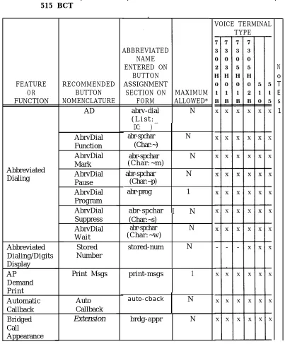
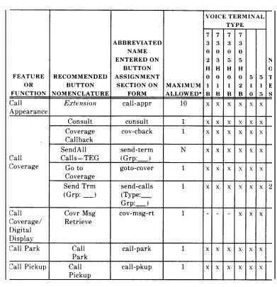
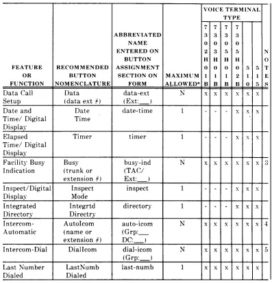
Before actually assigning features to terminals, review Tables 2-A, 2-B, and 2-C. These tables list the features that can be assigned to the voice terminals, the recommended button nomenclature, and the abbreviated feature name that must be entered on the form. The maximum number of buttons that can be assigned to that feature or function is also given. This recommended button nomenclature is used in the
AT&T System 75 User’s Guide Console
Operations, 555-200-700,
and theAT&T System
75User’s Guide Voice Terminal Operations,
555-200-701.
If different nomenclature is used, the related documentation should be marked to reflect the changes.The features chosen are assigned to the voice terminal by entering the abbreviated feature name on the Buttons field on the Voice Terminal Form.
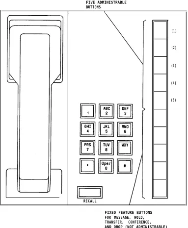
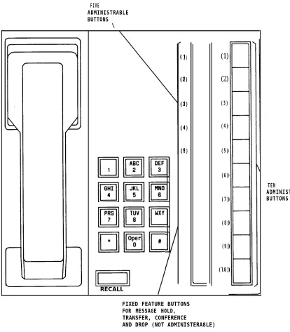
The button nomenclature must be entered on a label and inserted next to the button that is assigned the feature. A set of preprinted labels comes with each voice terminal. Figures 2-2 through 2-6 show the voice terminals, their button positions, and a suggested standard button arrangement. The nomenclature shown is the formal feature or function name. Use Tables 2-A, 2-B, and 2-C to determine the abbreviated name to enter on the form. Figures 2-7 through 2-9 show the administrable buttons for the Multibutton Electronic Telephone (MET) sets.
TABLE 2-A. Voice Terminal Button Assignments for 7303S, 7305S, 7403D, and 7405D
VOICE TERMINAL
ABBREVIATED TYPE
NAME ENTERED
ON 7 7 7 7 N
BUTTON 3 3 4 4 0
FEATURE RECOMMENDED ASSIGNMENT o 0 0 0 T OR BUTTON SECTION ON MAXIMUM 3 5 3 5 E
FUNCTION N O M E N C L A T U R E F O R M ALLOWED* s s D D s
A D abrv-dial N x x x x 1
(list:_ D C : _ )
AbrvDial abr-spchar N x x x x
Function (Char-)
AbrvDial abr-spchar N x x x x
Mark
Abbreviated (Char: -m)
Dialing AbrvDial abr-spchar N x x x x
Pause (Char: -p)
AbrvDial abr-prog 1 x x x x
Program
AbrvDial abr-spchar N x x x x
Suppress (Char: -s)
AbrvDial abr-spchar N x x x x
W a i t (Char: -w)
Abbreviated Stored stored-num 1 - - - x
Dialing/ Number
Digital Display
AP P r i n t print-msgs 1 x x x x
Demand Msgs
P r i n t
Automatic Auto auto-cback N x x x x
Callback Callback
*N= any number of buttons on the voice terminal can be assigned to this feature or function.
TABLE 2-A. Voice Terminal Button Assignments for 7303S, 7305S, ‘7403D. and 7405D (Contd)
VOICE TERMINAL
ABBREVIATED TYPE
NAME ENTERED
ON 7 7 7 7 N
BUTTON 3 3 4 4 0
FEATURE RECOMMENDED ASSIGNMENT 0 0 0 0 T OR BUTTON SECTION ON MAXIMUM 3 5 3 5 E FUNCTION NOMENCLATURE FORM ALLOWED* S S D D S
Bridged Extension brdg-appr N x x x x
Call
Appearance
Call
Extension
call-appr 10 x x x xAppearance
Consult consult 1 x x x x
Coverage cov-cback 1 x x x x
Callback
Call Send Trm send-term N x x x x
Coverage ( G r p : _ ) ( G r p : _ )
Go to goto-cover 1 x x x x
Coverage
Send All send-calls 1 x x x x 2
Calls (Type:_ Grp:_)
Gall
Coverage See UCD/DDC/Call Coverage
Answer Group
Call Covr Msg cov-msg-rt 1 - - - x
Coverage/ Retrieve Digital
Display
Call Park Call call-park 1 x x x x
Park
Call Pickup Call call-pkup 1 x x x x
Pickup
*N= any number of buttons on the voice terminal can be assigned to this feature or function.
TABLE 2-A. Voice Terminal Button Assignments for 7303S, 7305S, 7403D, and 7405D (Contd)
VOICE TERMINAL
ABBREVIATED TYPE
NAME ENTERED
O N 7 7 7 7
B U T T O N 3 3 4 4
FEATURE RECOMMENDED ASSIGNMENT o 0 0 0 OR BUTTON SECTION ON MAXIMUM 3 5 3 5 FUNCTION NOMENCLATURE FORM ALLOWED* s s D D
Data Call Setup D a t a data-ext N x x x x
(data ( E x t : _ ) extension #)
Date and Time/ Date date-time 1 - - - x
Digital Display Time
Elapsed Time/ Timer timer 1 - - - x
Digital Display
Facility Busy Busy busy-ind (TAC/ N x x x x
Indication (trunk or E x t : _ ) extension #)
Inspect/Digital Inspect inspect 1 - - - x
Display Mode
Integrated Integrtd directory 1 - - - x
Directory Directry
Intercom- AutoIcom auto-icom N x x x x
Automatic (name or G r p : _ D C : _ ) extension #)
Intercom-Dial DialIcom dial-icom N x x x x
( G r p : _ )
Last Number LastNumb last-numb 1 x x x . .x
Dialed Dialed
N o T E s
3
4
5
*N= any number of buttons on the voice terminal can be assigned to this feature or function.
TABLE 2-A. Voice Terminal Button Assignments for 7303S, 7305S, 7403D, and 7405D (Contd)
V O I C E
N o T E s 6 TERMINAL TYPE 7 7 4 4 0 0 3 5 D D x x x x ABBREVIATED NAME ENTERED ON BUTTON ASSIGNMENT SECTION ON FORM lwc-store 7 3 0 3 s x x 7 3 0 5 s x x FEATURE OR FUNCTION Leave Word Calling RECOMMENDED BUTTON NOMENCLATURE LWC MAXIMUM ALLOWED* 1 1 Cancel LWC Return Call lwc-cancel call-disp 1
I
x Message Retrieve Next Message 1 mesg-retr + .x x Leave Word Calling/ Digital Display 1 next — Delete Message Lock LWC delete-msg 1 + x x Iwc-lock 1 x Leave Word Calling (Remote .Message Waiting) Manual Signaling Message (name or extension #) aut-msg-wt ( E x t : _ )N x x
+ x x x x — x Signal (name or extension # )
s i g n a l ( E x t : _ ) N
*N= any number of buttons on the voice terminal can be assigned to this feature or function.
TABLE 2-A. Voice Terminal Button Assignments for 7303S, 7305S, 7403D, and 7405D (Contd)
VOICE TERMINAL
ABBREVIATED TYPE
NAME ENTERED
ON 7 7 7 7 N
BUTTON 3 3 4 4 0
FEATURE RECOMMENDED ASSIGNMENT o 0 0 0 T OR BUTTON SECTION ON MAXIMUM 3 5 3 5 E FUNCTION NOMENCLATURE FORM ALLOWED* s s D D s
Manual Msg Wait man-msg-wt N x x .x x 7
Message (name or ( E x t : _ ) Waiting extension #)
Normal Normal normal 1 - - - x
Mode/ Mode
Digital Display
Personal CO Line per-COline N x x x x 8
Central (telephone #) ( G r p : _ ) Office
Line
Privacy– Exclusn exclusion 1 x x x x
Manual Exclusion
Terminating Term Grp term-x-gr N x x x x 9
Extension (name or ( G r p : _ )
Group extension #)
UCD/DDC Make make-busy N x x x x
Busy ( G r p : _ )
UCD/DDC/ Coverage in-call-id N x x x x 10
Call (group number, ( T y p e : _ Coverage type or name or G r p : _ ) (Answer ext #)
Group)
*N= any number of buttons on the voice terminal can be assigned to this feature or function.
TABLE 2-A. Voice Terminal Button Assignments for 7303S, 7305S, 7403D, and 7405D (Contd)
NOTES
1. List:
DC: 2. Type:
Grp: 3 . T A C /
Ext: 4 . G r p :
5 . G r p : 6 . E x t : 7 . E x t : 8 . G r p : 9 . G r p : 10. Type:
G rp:
List number 1 to 3 where the destination number is stored.
Dial codes of destination number. A “c” for an individual extension, and a “t” for a terminating extension group.
The terminating extension group number (1 to W).
Extension number voice terminal to be monitored. Dial Icom group number (1 to 32). This extension and destination extension number must be in the same group.
Dial Icom group number (1 to W). Extension number of principal. The destination extension.
TABLE 2-B. Voice Terminal Button Assignments for 7302 H01B, 7303 H01B, 7305 H01B, 7305 H02B, AT&T Personal Terminal’ Model 510, and 515 BCT
FEATURE OR FUNCTION
DC:_____) abr-spchar N (Char:~)
( C h a r : ~ m ) Abbreviated
Dialing abr-spchar N (Char:~p) abr-prog 1
abr-spchar N ( C h a r : ~ w )
Abbreviated Dialing/Digits Display AP Demand P r i n t
stored-num N
Automatic Callback Bridged Call Appearance RECOMMENDED BUTTON NOMENCLATURE AD AbrvDial Function AbrvDial Mark AbrvDial Pause AbrvDial Program AbrvDial Suppress AbrvDial W a i t
Stored Number Print Msgs Auto Callback
Extension
ABBREVIATED NAME ENTERED ON BUTTON ASSIGNMENT SECTION ON FORM abrv-dial ( L i s t : _MAXIMUM ALLOWED*
N
abr-spchar N
abr-spchar I N (Char:~s)
print-msgs 1
auto-cback N
brdg-appr N
VOICE TERMINAL TYPE
*N= any number of buttons on the voice terminal can be assigned to this
N o T E s 1
feature or function.
TABLE 2-B. Voice Terminal Button Assignments for 7302 H01B. 7303 H01B. 7305 H01B, 7305 H02B, AT&T Personal Terminal Model’ 510. and 515 BCT (Contd)
*N= any number of buttons on the voice terminal can be assigned to this feature or function.
TABLE 2-B. Voice Terminal Button Assignments for 7302 H01B, 7303H01 B, 7305 H01B, 7305 H02B, AT&T Personal Terminal Model 510, and 515 BCT (Contd)
*N= any number of buttons on the voice terminal can be assigned to this feature or function.
TABLE 2-B. Voice Terminal Button Assignments for 7302 H01B, 7303 H01B, 7305 H01B, 7305 H02B, AT&T Personal Terminal Model 510. and 515 BCT (Contd)
FEATURE RECOMMENDED OR BUTTON Message Leave Retrieve Word Calling/ Next Digital Message Display Lock LWC Leave Word Calling (Remote Message Waiting) Manual Signaling Delete Message Message (name or extension # )
Signal (name or extension #) ABBREVIATED NAME ENTERED ON BUTTON ASSIGNMENT SECTION ON FORM lwc-store lwc-cancel call -disp mesg-retr next Iwc-lock delete-msg aut-msg-wt ( E x t : _ )
signal ( E x t : _ )
MAXIMUM ALLOWED* 1 1 1 1 1 1 1 N N
VOICE TERMINAL I
7 3 0 2 H () 1 B x x x x x 7 3 0 3 H o 1 B x— x — — — — — x — x — x — TYPE 7 7 3 3 0 0 5 5 H H o 0 1 2 B B x x x x ~ x x x x x x x x x
*N’= any number of buttons on the voice terminal can be assigned to this feature or function.
TABLE 2-B. Voice Terminal Button Assignments for 7302H01B, 7303H01B,
7305H01B, 7305H02B, AT&T Personal Terminal Model 510, 515BCT (Contd)
and
*N= any number of buttons on the voice terminal can be assigned to this feature or function.
TABLE 2-B. Voice Terminal Button Assignments for 7302H01B, 7303H01B, 7305H01B, 7305H02B, AT&T Personal Terminal Model 510, and 515 BCT (Contd)
NOTES
1. List: DC: 2. Type:
Grp: 3 . T A C /
Ext: 4 . G r p :
5 . G r p : 6 . E x t : 7 . E x t : 8 . G r p : 9 . G r p : 10. Type:
Grp:
List number 1 to 3 where the destination number is stored. Dial codes of destination number.
An “e” for an individual extension, “t” for a terminating extension group.
The terminating extension group number (1 to 32).
Extension number voice terminal to be monitored. Dial Icom group number (1 to 32). This extension and destination extension number must both be in the same group.
Dial Icom group number (1 to 32). Extension number of principal. The destination extension.
Central Office line group numbers (1 to 25).
Terminating Extension group number (1 to 32).
A “c” for coverage answer group, “h” for a uniform call distribution or direct department calling group.
TABLE 2-C. Voice Terminal Button Assignments for 10-, 20-, and 30-Button MET FEATURE OR FUNCTION DC:_____) Abbreviated Dialing N AP Demand P r i n t Automatic Callback Bridged Call Appearance Call Appearance RECOMMENDED BUTTON NOMENCLATURE AD AD Func AD Mark AD Paus AD Prog AD s u p s AD W a i t P r i n t Msgs Auto Call Back
Extension
Extension
ABBREVIATED NAME ENTERED ON BUTTON ASSIGNMENTSECTION ON MAXIMUM FORM ALLOWED*
abrv-dial N
(List: —
abr-spchar N
( C h a r : ~ )
abr-spchar (Char:~m) abr-spchar (Char: ~p) abr-prog
1
abr-spchar N (Char: ~s) abr-spchar N (Char: ~w) print-msgs 1brdg-appr
I
Ncall-appr I 10
VOICE TERMINAL TYPE
1 2 3
() 0 ()
M M M
E E E
T T T
x x x
x x x
x x x
x x x
x x x
x x x
x x x
x x x
x x .x
x x x
x x x
N O T E S 1
* N = any number of buttons on the voice terminal can be assigned to this feature
or function. The 10 MET can have only 5 maximum call appearance buttons.
TABLE 2-C. Voice Terminal Button Assignments for 10-, 20-, and 30-Button MET (Contd)
VOICE TERMINAL
ABBREVIATED TYPE
NAME ENTERED
ON 1 2 3 N
BUTTON o 0 O 0
FEATURE RECOMMENDED ASSIGNMENT M M M T
OR BUTTON SECTION ON MAXIMUM E E E E
FUNCTION NOMENCLATURE FORM ALLOWED* T T T s
Consult consult 1 x x x
Covr cov-cback 1 x x x
Call Back
Send Trm send-term x x x x
Call Coverage ( G r p : _ ) ( G r p : _ )
Go go to-covr 1 x x x
To Covr
Send send-calls 1 x x x 2
All ( T y p e : _ Calls G r p : _ )
Call Park Call call-park 1 x x x
Park
Call Pickup Call call-pkup 1 x x x
Pick u p
Data Call Setup D a t a data-ext N x x x
(Ext #) ( E x t : _ )
Intercom- Auto auto-icom N x x x 3
Automatic Icom ( G r p : _ )
(Ext #) ( D C : _ )
Intercom-Dial Dial dial-icom N x x x 4
Icom ( G r p : _ )
Last Number L a s t last-numb 1 x x x
Dialed Numb
Dial
TABLE 2-C. Voice Terminal Button Assignments for 10-, 20-, and 30-Button MET (Contd) VOICE TERMINAL FEATURE OR FUNCTION Leave Word Calling Manual Signaling Manual Message Waiting Personal Central Office Line Groups Privacy-Manual Exclusion Facility Busy Indication Terminating Extension Group UCD/DDC UCD/DDC/Call Coverage (Answer Group) ABBREVIATED NAME ENTERED
I
ON BUTTON RECOMMENDED ASSIGNMENTBUTTON SECTION ON MAXIMUM NOMENCLATURE FORM ALLOWED’
Cncl lwc-cancel 1
LWC
LWC lwc-store 1
Msg aut-msg-wt N
(name or Ext #) ( E x t : _ )
Man s i g n a l ( E x t : _ ) N Sgnl
(name or Ext #)
Msg man-msg-wt N
W a i t ( E x t : _ ) (name or Ext #)
Line per-COline N
(NXX-) ( G r p : _ ) (XXXX)
Excl exclusion 1
Busy busy-ind (TAC/ N
(Ext #) E x t : _ )
Term term-x-gr N
Grp ( G r p : _ )
(name or Ext #)
Make make-busy N
Busy (Grp:___)
Covr in-call-id N (group#, type, (Type:__
name, or Ext#) Grp:___)
1 0 M E T = x — x — x — x — x — x — x — x — x — x — x — TYPE
2 3 N
o 0 0
M M T
E E E
T T s
x x
x x
x x 5
x x
x x 6
x x 7
x x
x x 8
x x 9
x x
x x 10
TABLE 2-C. Voice Terminal Button Assignments for 10-, 20-, and 30-Button MET (Contd)
NOTES:
1. List: List number 1 to 3 where the destination number is stored.
DC: Dial code of destination number.
2. Type: An “e” for an individual extension, “t” for a terminating terminal group.
Grp: The terminating terminal group number (1 to 32).
4. G r p : 5 . E x t : 6 . E x t : 7 . G r p : 8 . T A C /
Ext:
3 . G r p : Dial icom group number (1 to 32). This extension and destination
extension number must both be in the same group.
Dial icom group number (1 to 32). Extension number of principal. The destination extension.
Central Office line group numbers (1 to ‘25).
Extension number voice terminal to be monitored.
9 . G r p : 10. Type:
Grp:
Terminating extension group number (1 to 32). A “c” for coverage answer group, “h” for a uniform call distribution or direct
department calling group.
Thirty-Four
/
Digital Di s play M o d u l e
Seven Administrable Buttons Thirty-Four Administerable Buttons . .
\ I
(1) (2) (3) (4) (5) {6) (7) \
1 (1)
(2) (3) (4) (5)
(6) (7} (8)
(13) I Abbreviated
I
Leave WordCalling
(14
(15
Abbreviated Dialing Abbreviated
(18) I
Abbreviated Dialing (19)
I
Abbreviated Dialing (20) Abbreviated
D i a l i n g (21)
I
Abbreviated DialingADMINISTRABLE DISPLAY BUTTONS
I
n
TEN
ADMINISTRABLE
TO KEYBOARD
Figure 2-6. Administrable Button Locations Terminal (BCT)
FIVE ADMINISTRABLE BUTTONS
I \
RECALL
(1)
(2)
(3)
(4)
(5)
FIXED FEATURE BUTTONS FOR MESSAGE, HOLD, TRANSFER, CONFERENCE, AND DROP (NOT ADMINISTRABLE)
FIVE
ADMINISTRABLE BUTTONS
\
1)
2)
3)
4)
5)
(1)
(2)
(3)
(4)
(5)
(6)
(7)
(8)
(9)
(l0)
TEN
ADMINISTRABLE BUTTONS
RECALL
FIXED FEATURE BUTTONS FOR MESSAGE HOLD, TRANSFER, CONFERENCE
AND DROP (NOT A