c e-ISSN: 2348-6848, p- ISSN: 2348-795X Volume 2, Issue 12, December 2015
International Journal of Research (IJR)
Available at http://internationaljournalofresearch.org
Modeling &Simulation of 11-Level STATCOM for
Distributed Energy Systems with Fuzzy controller
Mr. V.Shivakrishna*1& Mr.C.Bala Chandra Reddy*2
M.Tech Student, Department of Electrical and Electronics Engineering#1.
Asso. Professor, Department of Electrical and Electronics Engineering#2.
Chilkurbalaj instituteofTechnology, Telangana State, India.
Abstract:
In this paper, a new single-phase wind energy inverter (WEI) with flexible AC transmission system (FACTS) capability is presented. The proposed inverter is placed between the wind turbine and the grid, same as a regular WEI, and is able to regulate active and reactive power transferred to the grid. This inverter is equipped with distribution static synchronous compensators option in order to control the power factor (PF) of the local feeder lines. Using the proposed inverter for small-to medium-size wind applications will eliminate the use of capacitor banks as well as FACTS devices to control the PF of the distribution lines. The goal of this paper is to introduce new ways to increase the penetration of renewable energy systems into the distribution systems. This will encourage the utilities and customers to act not only as a consumer, but also as a supplier of energy. Moreover, using the new types of converters with FACTS capabilities will significantly reduce the total cost of the renewable energy application. In this paper, modular multilevel converter is used as the desired topology to meet all the requirements of a single-phase system such as compatibility with IEEE standards, total harmonic distortion (THD), efficiency, and total cost of the system. The proposed control strategy regulates the active and reactive power using power angle and modulation index, respectively. The function of the proposed inverter is to transfer active power to the grid as well as keeping the PF of the local power lines constant at a target PF regardless of the incoming active power from the wind turbine. The simulations for an11-level inverter have been done in MATLAB/Simulink. To validate the simulation results, a scaled prototype model of the proposed inverter has been built andtested.
c e-ISSN: 2348-6848, p- ISSN: 2348-795X Volume 2, Issue 12, December 2015
International Journal of Research (IJR)
Available at http://internationaljournalofresearch.org
I. INTRODUCTION
The Role of power electronics in distribution systems has greatly increased recently. The power electronic devices are usually used to convert the non conventional forms of energy to the suitable energy for power grids, in terms of voltage and frequency. In permanent magnet (PM) wind applications, a back-to-back converter is normally utilized to connect the generator to the grid. A rectifier equipped with a maximum power point tracker (MPPT),converts the output power of the wind turbine to a dc power. The dc power is then converted to the desired ac power for power lines using an inverter and a transformer. With recent developments in wind energy, utilizing smarter wind energy inverters (WEIs) has become an important issue. There are a lot of single-phase lines in the United States, which power small farms or remote houses [1], [2]. Such customers have the potential to produce their required energy using a small-to-medium-size wind turbine. Increasing the number of small-to-medium wind turbines will make several troubles for local utilities such as harmonics or power factor (PF)issues. A high PF is generally desirable in a power system to decrease power losses and improve voltage regulation at the load. It is often desirable to adjust the PF of a system to near1.0. When reactive elements supply or absorb reactive power near the load, the apparent power is reduced. In other words, the current drawn by the load is reduced, which decreases the power losses. Therefore, the voltage regulation is improved if the reactive power compensation is performed near largeloads.
Traditionally, utilities have to use capacitor banks to compensate the PF issues, which will increase the total cost of the system. The modern ways of controlling the PF of these power lines is to use small distribution static synchronous compensators (D-STATCOMs). The D- STATCOMs are normally placed in parallel with the distributed generation systems as well as the power systems to operate as a source or sink of reactive power to increase the power quality issues of the power lines. Using regular STATCOMs for small-to-medium size single-phase wind applications does not make economic sense and increase the cost of the system significantly. This is where the idea of using smarter WEIs with FACTS capabilities shows itself as a new idea to meet the targets of being cost-effective as well as compatible with IEEE standards. The proposed inverter in this paper is equipped with a D-STATCOM option to regulate the reactive power of the local distribution lines and can be placed between the wind turbine and the grid, same as a regular WEI without any additional cost. The function of the proposed inverter is not only to convert dc power coming from dc link to a suitable ac power for the main grid, but also to fix the PF of the local grid at a target PF by injecting enough reactive power to the grid. In the proposed control strategy, the concepts of the inverter and the D-STATCOM
have been combined to make a new inverter, which possesses FACTS capability with no additional cost. The
proposed control strategy allows the inverter to act as an inverter with D-STATCOM option when there is enough wind to produce active power, and to act as a D-STATCOM when there is no wind. The active power is controlled byadjusting
Fig.1. Complete configuration of the proposed inverter with FACTScapability.
The power angle δ, which is the anglebetweenthevoltagesoftheinverterandthegrid,andreactivep owerisregulated by the modulation index m. There arealargenumber of publications on integration ofrenewableenergysystems into power systems. A list ofcompletepublicationson FACTS applications for grid integration of windandsolarenergy was presented in [3]. In [4],new commercialwindenergy converters with FACTS capabilitiesareintroducedwithout any detailed information regarding theefficiencyorthe topology used for the converters. In [5], a completelistofthe most important multilevel inverters wasreviewed.Also,different modulation methods such as sinusoidalpulsewidthmodulation(PWM) selective harmonicelimination,optimizedharmonic stepped waveform technique, andspacevectormodulation were discussed and compared.Amongallmultilevel
topologies [6]–[9], the cascaded H-bridge multilevel converter is very well knownforSTATCOMapplications for several reasons [10]– [12]. The mainreasonisthat it is simple to obtain a high number of levels,whichcanhelp to connect STATCOM directly to medium voltagegrids.
c e-ISSN: 2348-6848, p- ISSN: 2348-795X Volume 2, Issue 12, December 2015
International Journal of Research (IJR)
Available at http://internationaljournalofresearch.org
applications of custom power electronics in renew able energy systems exist, including [17] an application of a custom power interface where two modes of operation, including an active power filter and a renewable energy STATCOM. Another application [18] looks at the current source inverter, which controls reactive power and regulates voltage at the point of common coupling (PCC). Varmaet al.[19], [20] propose an application of photovoltaic (PV) solar inverter as STATCOM in order to regulate voltage on three phase power systems, for improving transient stability and power transfer limit in transmission systems. The authors called their proposed systemPV-STATCOM.
Similar to wind farms (when there is no wind), solar farms are idle during nights. We proposed a control strategy that makes the solar farms to act as STATCOMs during night when they are not able to produce active power. The main purpose of the PV-STATCOM system is to improve the voltage control and the PF correction on three-phase transmission systems. In this paper, the proposed WEI utilizes MMC topology, which has been introduced recently for HVDC applications. Replacing conventional inverters with this inverter will eliminate the need to use a separate capacitor bank or a STATCOM device to fix the PF of the local distribution grids. Obviously, depending on the size of the power system, multiple inverters might be used in order to reach the desired PF. The unique work in this paper is the use of MMC topology for a single phase voltage-source inverter, which meets the IEEE standard519 requirements, and is able to control the PF of the grid regardless of the wind speed Fig. 1 shows the complete grid-connected mode configuration of the proposed inverter. The dc link of the inverter is connected to the wind turbine through a rectifier using MPPT and its output terminal is connected to the utility grid through a series-connected second-order filter and a distributiontransformer.
II. MODULAR MULTILEVELCONVERTER MMC has gained increasing attention recently. A number of papers were published on the structure, control, and application of this topology [21], [22], but none has suggested the use of that for inverter + D-STATCOM application. This topology consists of several half-bridge (HB) sub modules (SMs) per each phase, which are connected in series. An n-level single phase MMC consists of a series connection of 2(n − 1)basic SMs and two buffer inductors. Each SM possesses two semiconductor switches, which operate in complementary mode, and one capacitor. The exclusive structure of MMC becomes it an ideal candidate for medium-to-high-voltage applications such as wind energy applications. Moreover, this topology needs only one dc source, which is a key point for wind applications. MMC requires large capacitors which may increase the cost of the systems; however, this problem is offset by the lack of need for any snubber circuit. The main benefits of the MMC topology are: modular design based on identical converter cells, simple voltage scaling by a series
connection of cells, simple realization of redundancy, and possibility of a common dc bus. Fig. 2 shows the circuit configuration of a single-phase MMC and the structure of its SMs consisting of two power switches and a floating capacitor. The output voltage of each SM (vo) is either equal
to its capacitor voltage (vc) or zero, depending on the
switchingstates.
Fig.2.Structure of a single-phase MMC inverter structure.
The buffer inductors must provide current control in each phase arm and limit the fault currents. To describe the operation of MMC, each SM can be considered as a two poles witch. If Sui, which is defined as the status of the ith sub module in the upper arm, is equal to unity, then the outputoftheith SMisequaltothecorrespondingcapacitor
voltage; otherwise it is zero. Likewise, if Sli which is defined
as the status of the ith sub module in the lower arm, is equal to unity, then the output of the ith lower SM is equal to the corresponding capacitor voltage; otherwise it is zero. Generally, when Sui or Sli is equal to unity, the ith upper or
lower SM is ON; otherwise it is OFF. Therefore, the upper and lower arm voltages of the MMC are asfollows:
(1)
(2) Where v11 and v12 are the voltages of the upper and lower
buffer inductors, n is the number of voltage levels, and vci is
thevoltageoftheith SMscapacitorinupperarmorlower
arm. A single-phase 11-levelMMC inverter consists of 20 SMs which translates to 40 power switches, 20 capacitors, and2 buffer inductors. The dc and ac voltages of the 11- levelMMC are describedby
c e-ISSN: 2348-6848, p- ISSN: 2348-795X Volume 2, Issue 12, December 2015
International Journal of Research (IJR)
Available at http://internationaljournalofresearch.org
(4)
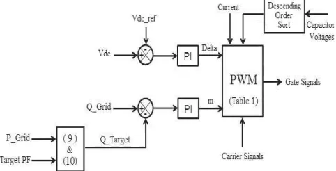
III. PROPOSED CONTROLSTRATEGY The proposed controller consists of three major functions. The first function is to control the active and reactive power. Transferred to the power lines, the second function is to keep thevoltagesoftheSMs’capacitorsbalanced,andthethird function is to generate desired PWM signals. Fig. 3 shows the complete proposed controller system. The aim of the designed inverter is to transfer active power coming from the wind turbine as well as to provide utilities with distributive control of volt-ampere reactive (VAR) compensation and PF correction of feeder lines. The application of the proposed inverter requires active and reactive power to be controlled fully independent, so that if wind is blowing, the device should be working as a normal inverter plus being able to fix the PF of the local grid at a target PF (D-STATCOM option), and if there is no wind, the device should be only operating as a D-STATCOM (or capacitor bank) to regulate PF of the local grid. This translates to two modes of operation: 1) when wind is blowing and active power is coming from the wind turbine: the inverter plus D-STATCOM mode. In this mode, the device is working as a regular inverter to transfer active power from the renewable energy source to the grid as well as working as a normal D-STATCOM to regulate the reactive power of the grid in order to control the PF of the grid and 2) when wind speed is zero or too low to generate active power: the D-STATCOMmode.
Fig. 3.Schematic of the proposed controllersystem.
In this case, the inverter is acting only as a source of reactive power to control the PF of the grid, as a D- STATCOM. This option eliminates the use of additional capacitor banks or external STATCOMs to regulate the PF of the distribution feeder lines. Obviously, the device is capable of outputting up to its rated maximum real power and/or reactive power, and will always output all real power generated by the wind turbine to the grid. The amount of reactive power, up to the design maximum, is dependent only on what the utility asks the device to produce. Generally, (5) and (6) dictate the power flow between a STATCOM device and powerlines
(5)
(6) Where X is the inductance between the STATCOM (here as inverter) and the grid which is normally considered as output filter inductance added to the transmission line inductance. The root mean square (RMS) voltage of the STATCOM (=inverter) is given as Es and is considered to be out of phase by an angle of δ to the RMS line voltage E1.In the proposed control strategy, active and reactive power transferred between the inverter and the distribution grid is controlled by selecting both the voltage level of the inverter and the angle δ between the voltages of inverter and grid, respectively. The amplitude of the inverter voltage is regulated by changingthe modulation index m and the angle δ by adding a delay to the firing signals whichconcludes
(7)
c e-ISSN: 2348-6848, p- ISSN: 2348-795X Volume 2, Issue 12, December 2015
International Journal of Research (IJR)
Available at http://internationaljournalofresearch.org
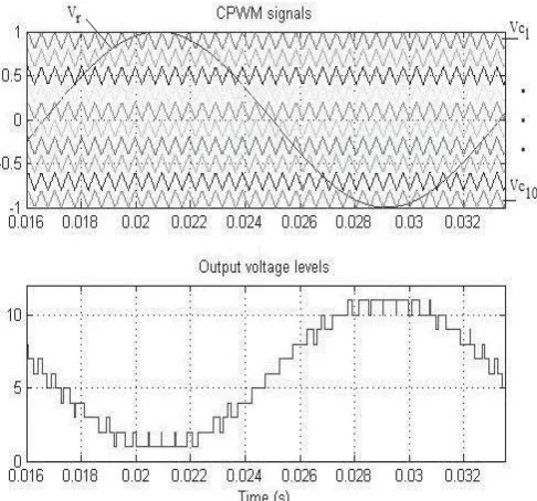
Fig. 4. CPWM waveforms for an11-level MMC inverter, and the generated output voltagelevels.
The power angle is also determined by comparing the actual dc voltage of the inverter with a reference value. A PI compensator determines the desired value for the power angle. The second function of the controller systems is to keep the capacitors’ voltages balanced. In order to do this, a carrier based pulse width modulation (CPWM) method [25], [26] is used. The top graph in Fig. 4 shows the reference signal and the carrier waveforms for an 11-level MMC inverter using CPWM technique. The bottom graph of Fig. 4 shows the output voltage levels generated based on Table I. In an 11-level CPWM technique, ten carrier signals are compared with a reference sinusoidal signal. In Fig 4, based on the phase of the reference signal (vr), there are 11
operating regions where each region defines a voltage level in theoutput
(9) Where nupperArm and nlower Arm are the numbers of SMs which are ON (Scis ON and Smis OFF in Fig. 1) in the upper armor lower arm, respectively. In an 11-level MMC inverter, there are ten upper and ten lower SMs where each SM has a capacitor. For instance, in voltage level 1 of Table I, all the upper SMs should be OFF and all the lower SMs should be ON, which translates to the fact that the main switches Sm of all upper SMs and the auxiliary switches (Sc) of all lower SMs have to be ON and all the other switches have to be OFF. In this case, the input dc voltage is applied only to the ten lower capacitors, sothat
c e-ISSN: 2348-6848, p- ISSN: 2348-795X Volume 2, Issue 12, December 2015
International Journal of Research (IJR)
Available at http://internationaljournalofresearch.org
the output voltage is vDC/2. Fig. 5 illustrates the selection of
capacitors for different voltage levels shown in Table I. The most critical issue to control MMC is to maintain the voltage balance across all the capacitors. Therefore, the SMs’ voltages are measured and sorted in descending order during each cycle. If the current flowing through the switches is positive, so that capacitors are being charged, nupper Armand nupperArm and of the SMs in upper arm and lower arm with the lowest voltages are selected, respectively. As a result, ten capacitors with lowest voltages are chosen to be charged.
Likewise, if the current flowing through the switches is negative, so that capacitors are being discharged, nupper Armand nupperArm of the SMs in upper arm and lower arm with highest voltages are selected, respectively. As a result, ten capacitors with highest voltages are chosen to be discharged. Consequently, the voltages of the SMs’ capacitors are balanced. Considering Table I and based on the direction of the current flowing through the switches, the proper algorithm will be selected to maintain capacitor balance. The third function of the controller system is the PWM generation block. In this block, based on the desired modulation index, power angle, voltages of the capacitors, direction of the current flowing through the switches and using Table I, the controller generates the PWM signals in order to meet all the systemrequirements.
IV. SIMULATION AND PRACTICALRESULTS The design of an 11-level MMC inverter was carried out in MATLAB/ Simulink. The simulation is 20 s long and contains severe ramping and de-ramping of the wind turbine. The goal is to assess the behavior of the control system in the worst conditions. Table II shows the values of the parameters used for the simulation. Before t = 6 s, there is no wind to power the wind turbine; therefore, the dc link is open- circuited. At t = 6 s, the input power of the inverter is ramped up to 12 kW in 5 s, and then ramped down to 3.5 kW 4 s later. Fig. 6 shows the output active power from the wind turbine.
Fig. 5.Matlab/simulink model of the proposedmethod.
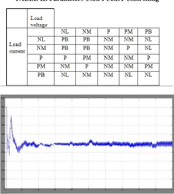
TABLE II: Parameters Used FUZZY controlling
Fig.6. Simulated output active power from the wind turbine.
In the simulation, the local load makes the PF 0.82. When the simulation starts, the inverter provides enough compensation to reach the target PF 0.90. Fig. 7 shows the output active and reactivepower
c e-ISSN: 2348-6848, p- ISSN: 2348-795X Volume 2, Issue 12, December 2015
International Journal of Research (IJR)
Available at http://internationaljournalofresearch.org
Fig. 8.Simulated output voltage of an 11-levelinverter.
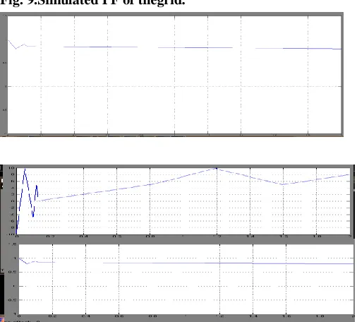
from the wind turbine and the grid. After t = 6 s, the output power of the wind turbine is increased, and as a result the level of active power provided by the feeder line is decreased by the same amount. The simulated output voltage of the inverter before the filter is shown in Fig. 8. Fig. 9 shows the PF of the grid. The PF of the grid is constant at 0.90 regardless of the active power from the wind turbine, showing that the main goal of the inverter is achieved. The set-point for dc link voltage of the inverter is 2000 V and the RMS value of the output ac voltage is 600 V. The delta and modulation index graphs are shown in Fig. 10. As soon as the active power comes from the wind turbine, the controller system increases the value of the power angle in order to output more active power to the grid. Therefore, the active power provided from the feeder lines to the load is decreased, and as a result the reactive power from the feeder lines is decreased. Consequently, the modulation index is increased by the controller system to inject more reactive power needed by theload.
Fig. 9.Simulated PF of thegrid.
Fig. 10. Simulated delta and modulation index of the 11- level inverter. To validate the simulation results, a scaled version of the proposed inverter has been built andtested.
V. CONCLUSION
In this paper, the concept of a new multilevel inverter with FACTS capability for small-to-mid-size wind installations is presented. The proposed system demonstrates the application of a new inverter with FACTS capability in a single unit by without any additional cost. Replacing the traditional renewable energy inverters with the proposed inverter will eliminate the need of any external STATCOM devices to regulate the PF of the grid. Clearly, depending on the size of the compensation, multiple inverters may be needed to reach the desired PF. This shows a new way in which distributed renewable sources can be used to provide control and support in distribution systems the proposed controller system adjusts the active power by changing the power angle (delta) and the reactive power is controllable by the modulation index m. The simulation results for an 11- level inverter are presented in MATLAB/Simulink. To validate the simulation results, a scaled prototype of the proposed 11-level inverter with D-STATCOM capability is built and tested. Practical results show good performance of the proposed control strategy even in severeconditions.
VI. REFERENCES
[1] U.S. Solar Market Insight, 2010 Year End Review Executive Summary,SEIA, Washington, DC, USA,2011.
[2] AWEA U.S. Wind Industry Annual Market Report Year Ending 2010,AWEA, Washington, DC, USA,2011.
[3] S. A. Rahman, R. K. Varma, and W. H. Litzenberger, “Bibliography ofFACTS applications for grid integration of wind and PV solar powersystems: 1995–2010 IEEE working group report,” in Proc. IEEE PowerEnergy Soc. General Meeting, Jul. 2011, pp.1–17.
[4] A. Beekmann, J. Marques, E. Quitmann, and S. Wachtel, “Wind energyconverters with FACTS capabilities for optimized integration of windpower into transmission and distribution systems,” in Proc. CIGRE/IEEEPES Joint Symp. Integr. Wide, Scale Renew. Resour. Power Del. Syst.,Jul. 2009, pp.1–9.
[5] J. Rodriguez, J. S. Lai, and F. Z. Peng, “Multilevel inverters: Survey oftopologies, controls, and applications,” IEEE Trans. Ind. Appl., vol. 49,no. 4, pp. 724–738, Aug. 2002.
[6] F. Z. Peng, J. S. Lai, J. W. McKeever, and J. VanCoevering, “A multilevelvoltage-source inverter with separate DC sources for static VArgeneration,” IEEE Trans. Ind. Appl., vol. 32, no. 5, pp. 1130–1138,Oct.1996.
c e-ISSN: 2348-6848, p- ISSN: 2348-795X Volume 2, Issue 12, December 2015
International Journal of Research (IJR)
Available at http://internationaljournalofresearch.org
[8] S. Kouro, M. Malinowski, K. Gopakumar, J. Pou, L. G. Franquelo,B. Wu, et al., “Recent advances and industrial applications of multilevelconverters,” IEEE Trans. Ind. Electron., vol. 57, no. 8, pp. 2553–2580,Aug.2010.
[9] C. Tareila, P. Sotoodeh, and R. D. Miller, “Design and control ofa single-phase D-STATCOM inverter for wind application,” in Proc.PEMWA, Jul. 2012, pp.1–5.
Mr.V.SHIVAKRISHNA,MTECH(POWERELECT RONICSENGINEERING)PURSUING In
Chilkurbalaj instituteofTechnology, Aziznagar,Moinabad,
Telangana State ,India.
EMail id: [email protected]
Mr .C.BALA CHANDRA REDDY, He received B.Tech degree in Electrical and Electronics Engineering in the year of 2002 & M.Tech degree in Power System in the year of 2005 from NIT Warangal in 2005 . He is currently working as An
ASSO.PROF&HOD in EEE Department in
CHILKUR BALAJI INST OF TECH ,RVS NAGAR AZIZ NAGAR, Moinabad ,Telangana State ,India