Power Quality Issues and its Mitigation by
using D-Statcom
Lakshmi Iyer
1,
Dr.R.Prakash
2P.G. Student , Dept. of EEE, Vivekanandha College of Engineering For Women (Autonomous), Tiruchengode, Tamilnadu, India1
Professor, Dept. of EEE, Vivekanandha College of Engineering For Women (Autonomous), Tiruchengode, Tamilnadu, India 2
ABSTRACT: : The electrical energy is one of the easily used forms of energy. It can be easily converted to other forms of energy. With the advancement of technology, the dependency on the electrical energy has been increased greatly. Computer and telecommunication networks, railway network banking, post office, life support system are few application that just cannot function without electricity. At the same time these applications demand qualitative energy. However, the quality of power supplied is affected by various internal and external factors of the power system. The presence of harmonics, voltage and frequency variations deteriorate the performance of the system. In this project the frequently occurring power quality problem- voltage variation is discussed. The voltage sag/dip is the most frequently occurring problem. There are many methods to overcome this problem. Among them the use of FACT devices is an efficient one. This project presents a comparison of the FACT device DVR and D-STATCOM mitigating voltage sags. The above device is studied and analyzed. And also the control strategies to control this device are presented in this project. The proposed control strategies are simulated in MATLAB SIMULINK environment and the results are presented. A comparative study based on the performance of these devices in mitigating voltage sag is also presented.
KEYWORDS: DVR, D-STATCOM, Networks
I.INTRODUCTION
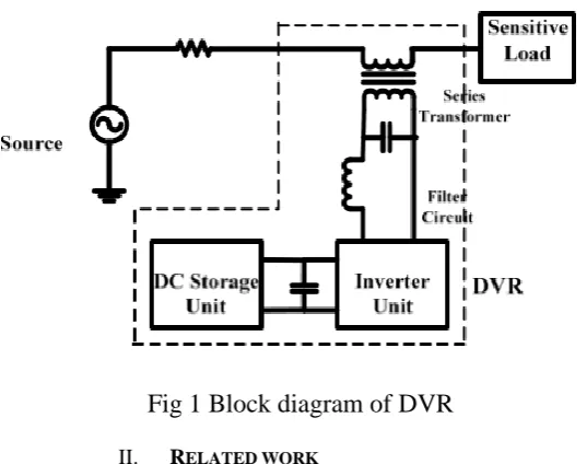
A) BLOCK DAIGRAM
Fig 1 Block diagram of DVR
II. RELATED WORK
A static synchronous compensator (STATCOM), also known as a static synchronous condenser (STATCON), is a regulating device used on alternating current electricity transmission networks. It is based on a power electronics voltage-source converter and can act as either a source or sink of reactive AC power to an electricity network. If connected to a source of power it can also provide active AC power. It is a member of the FACTS family of devices. A static VAR compensator can also be used for voltage stability. However, a STATCOM has better characteristics than an SVC. When the system voltage drops sufficiently to force the STATCOM output current to its ceiling, its maximum reactive output current will not be affected by the voltage magnitude. Therefore, it exhibits constant current characteristics when the voltage is low under the limit. In addition, the speed of response of a STATCOM is faster than that of an SVC and the harmonic emission is lower.
B
)BLOCK DIAGRAMFig.2 Schematic Diagram of D-STATCOM
III.VOLTAGE SAG MITIGATION BY D STATCOM
As in the case of DVR, the VSI generates voltage by taking the input from the charged capacitor. It uses PWM switching technique for this purpose. This voltage is delivered to the system through the reactance of the coupling transformer. The voltage difference across the reactor is used to produce the active and reactive power exchange between the STATCOM and the transmission network. This exchange is done much more rapidly than a synchronous condenser and improves the performance of the system.
A) OPERATING PRINCIPLE
A D-STATCOM is capable of compensating either bus voltage or line current. It can operate in two modes based on the parameter which it regulates. They are-
Voltage Mode Operation: In this mode, it can make the bus voltage to which it is connected a sinusoid. This can be
achieved irrespective of the unbalance or distortion in the supply voltage.
Current Mode Operation: In this mode of operation, the D-STATCOM forces the source current to be a balanced
sinusoid irrespective of the load current harmonics.
The basic operating principle of a D-STATCOM in voltage sag mitigation is to regulate the bus voltage by generating or absorbing the reactive power. Therefore, the D-STATCOM operates either as an inductor or as a capacitor based on the magnitude of the bus voltage.
IV. INTERFACING THE ELECTRICAL CIRCUIT WITH SIMULINK
The Voltage Measurement block acts as an interface between the SimPowerSystems blocks and the Simulink blocks. For the system shown above, you implemented such an interface from the electrical system to the Simulink system. The Voltage Measurement block converts the measured voltages into Simulink signals.Similarly, the Current Measurement block from the Measurements library of powerlib can be used to convert any measured current into a Simulink signal.You can also interface from Simulink blocks to the electrical system. For example, you can use the Controlled Voltage Source block to inject a voltage in an electrical circuit, as shown in the following figure.
A)Measuring Voltages and Currents:
When you measure a current using a Current Measurement block, the positive direction of current is indicated on the block icon (positive current flowing from + terminal to – terminal). Similarly, when you measure a voltage using a Voltage Measurement block, the measured voltage is the voltage of the + terminal with respect to the – terminal. However, when voltages and currents of blocks from the Elements library are measured using the Multimeter block, the voltage and current polarities are not immediately obvious because blocks might have been rotated and there are no signs indicating polarities on the block icons.
V. SIMULATION RESULTS
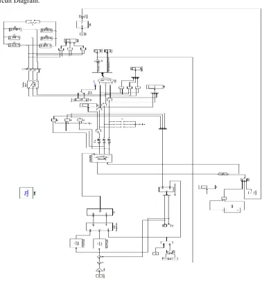
A)
Simulation Circuit Diagram:B)
ABC-DQ Tranformation:Fig 5
ABC-DQ TRANFORMATION:C)DQ-Alpha Beta Transformation:
Fig 6
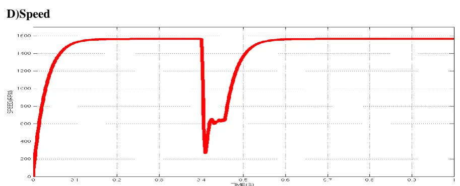
ALPHA BETA TRANSFORMATIOND)Speed
E)Torque:
F)Output Voltage:
H)Current Harmonic the After Compensation
VI. CONCLUSION AND FUTURE WORK
Electrical power systems are combinations of electrical circuits and electromechanical devices like motors and generators. Engineers working in this discipline are constantly improving the performance of the systems. Requirements for drastically increased efficiency have forced power system designers to use power electronic devices and sophisticated control system concepts that tax traditional analysis tools and techniques. Further complicating the analyst's role is the fact that the system is often so nonlinear that the only way to understand it is through simulation .Land-based power generation from hydroelectric, steam, or other devices is not the only use of power systems. A common attribute of these systems is their use of power electronics and control systems to achieve their performance
REFERENCES
1. Konstantinos A.Raftopoulos, Klimlis S.Ntalianis, D.Sourlas, And Stefano’s D.Kollias,”Mining User Queries With Markov Chains: Application To Online Image Retrieval”, IEEE Transcations On Knowledge And Data Engineering, Vol. 25, No. 2, Pp 433-447.February 2013.
2. R. Datta, D. Joshi, J. Li, And J.Z. Wang, “Image Retrieval: Ideas, Influences, And Trends Of The New Age,” ACM Computing Surveys, Vol. 40, No. 2, Pp. 1-60, 2008.
3. Comscore’s Report Article,”Comscores Qsearch 2.0 Service,” Comscores Report Article, Www.Comscore.Com,2007 4. Govindarajulu - IBM PC And Clones - TMH Publishing Company, New Delhi.
5. M. Radhakrishnan & D. Balasubramanian - Computer Installation & Troubleshooting – ISTE Learning Material. 6. Peter Norton - Introduction To Computers - TMH Publishing Company, New Delhi.