Comparative Analysis of Low Cost 3D
Scanning Methods by Evaluating its
Measuring Capability
Rohit Gupta 1, Himanshu Chaudhary 2
Master Student, Department of Mechanical Engineering, Sri Sai College of Engg and Technology,
Badhani Pathankot, India. 1
Assistant Professor, Department of Mechanical Engineering, Sri Sai College of Engg and Technology,
Badhani Pathankot, India.2
ABSTRACT: The 3D scanning framework is progressively utilized as a part of different fields. The 3D scanner having the ability of catching the genuine 3D questions in digitized frame in the PC world. The age of 3D demonstrate is required in different applications like in assembling industry to figuring out the current parts, to review the nature of assembling segment, activity industry to show the character from this present reality. The 3D examining brings about straightforwardness in the investigation procedure and thus diminishes the assembling costs. The utilization of 3D filtering is improved by bringing down the cost of 3D checking gadget. In this paper the past examinations done on the improvement of 3D checking framework are considered and furthermore the different filtering factors are contemplated which brings about increment the nature of 3D examining framework. Analysts have likewise considered different checking strategies and different examining factors are contemplated which enormously impact the nature of 3D filtering to filter the segments it is discovered that Laser Light Scanning and Structured light filtering are generally utilized as a part of figuring out and review purposes as the outcomes create by these techniques are very precise.
KEYWORDS: 3D Scanning, Reverse Engineering, Laser Light scanning.
I. INTRODUCTION
question onto the computer in a way, bringing about 3D check data.3D information got from 3D examining is the correct reproduction of the current item. The 3D filter information got can be utilized for different purposes like acquiring the physical properties of the current segments, for investigating thedifferent parameters of the segments against existing illustration.
3D Laser Scanners are classified into three main categories: Laser triangulation
Time of flight Phase Shift
Laser triangulation isachieved by a laser line or point onto a object and afterward catching its appearance with a sensor situated at a known separation from the lasers Source. The subsequent reflection point can be captured to yield 3D estimations of the part accomplished by projecting a laser line or point onto an object and then capturing its reflection with a sensor located at a known distance from the lasers source. The resulting reflection angle can be interpreted to yield 3D measurements of the part.
Time of flight laser scannersproduce a beam of laser light that is reflected off of the object to be examined. The subsequent reflection is distinguished with a sensor and the time that slips by amongst outflow and recognition yields the scan results of the object since the speed of the laser light is absolutely known.
White Light Scanning (structured light scanning)In this method a pattern of light (usually black and white lines) falls on the surface to be scanned and use sensors (typically CCD cameras) to capture images of the object with the patterns projected on it. The camera acts as a sensor to observe these patterns and captures it.
The uses of the scanning technology are:
Reverse Engineering
Inspecting the quality
Computation of 3D Animation Character from Real world
Increase the speed of inspection
Increasing accuracy working with complex parts and shapes
The initial step of the figuring out includes the creation of 2D drawing by estimating the physical measurements of the part under examination. For each current item it is impra-ctical to make 2D drawing for the parts whose shapes are exceptionally unpredictable. For those segments 3D CAD demonstrate is produced by utilizing 3D examining process.
II. LITERATURE SURVEY
projector is used to capture the image at the rate of 120 frames per second. In phase shifting technique for construction of 3d image it requires three frames therefore the image acquisition speed of this system is 40 frames per second. In this system the more the pattern is projected on to object the better the accuracy is obtained. Lanman et al. [6] (2007)paper presents a new method of scanning for obtaining complete3D surface models using a structured light projector using a pair of planar mirrors, and one or more synchronizedcameras. In this method of 3d scanning the structured light patterns are used to illuminate the components not from one side but from all the sides of the components to be scanned. The system requires that projected planes of light to be parallel so the orthographic projector is constructed using a Fresnel Lense and DLP projector. The structured light fall on the segment and enlighten the part from every one of the sides, by utilizing two plane mirrors we get one genuine picture and four virtual pictures and these five pictures together will make the segment obvious from all around and subsequently the filtered comes about comprises of five sweeps of five distinct perspectives and the segment is totally examined.Peiravi&Taabbodi (2010) [7]presents a laser triangulation 3D scanner utilizing two distinctive shading laser one is green and other one is red and one ccd camera, by utilizing this approach it is discovered that the impediment issue is limited and the general framework unwavering quality is expanded. The proposed scanner is considerably less expensive and is less perplexing than the scanners having two cameras and one laser.Martynov et al. (2011) [9] solved the problem of video projector calibration. In this method the projector is calibrated by inverting the camera calibration work flow. The calibration of projector requires a single camera, which does not need to be calibrated and which can be uses as a sensor to see whether projected dots and calibration pattern landmarks, such as the checkerboard corners, coincide.Park et al. (2011) [10]utilizes a hand-held 3D filtering procedure to recreate 3D models of genuine articles. A grouping of pictures is caught from a hand-held stereo camera and these pictures are consequently enlisted to a reference organize framework.Ouji et al. (2013)[12] proposed a structured light camera/projector system for 3D scanning, using three calibrated cameras coupled with a non calibrated projector device, for 3D face scanning.Aubreton (2013) et al. [13]presents a new method called Scanning from heating is introduced to scan highly reflective metallic surfaces, glass materials..In this paper the new method is used to scan highly reflective surfaces with good quality scan results. The reflective surface which has to be scanned is heated by a laser light source and after heating its thermal emission is used to obtain the scan results.Reyes et al. (2013) [14] a prototype of 3D scanning device is developed that can be used to obtain virtual 3D objects by using one d optical distance sensor. Zhao et al. (2014) [15] presents a method of calibration for stereo vision system based on phase matching and bundle adjustment algorithm. For calibration of the camera intrinsic and extrinsic parameters are required as the position of the camera are mechanically held at the desired position the intrinsic parameters of the camera will remain same. Gerbino et al.(2015) [16] studies various scanning factors that greatly effects the results of the laser based 3Dscanning system. The factors that influence the quality of 3D scanning are scanning resolution and accuracy and the external scanning parameters which influence the quality of 3D scanning are ambient light, surfacecolour, glossiness and shape.Galantucci et al. (2015) [17]built up the 3D laser scanner utilizing semi automatic minimal effort mechanized framework. This paper is centered around the testing and execution of minimal effort semi computerized laser light scanning framework. The scanner depends on the product stage of the DAVID Laser Scanner Vision Systems GmbH's., the development of the laser stripe was controlled by utilizing Mach3 CNC programming which controls the development of stepper engine utilizing controller. Wang &Feng, (2016) [18] studied the effects of scanning orientation on outlier formation in 3D laser scanning of reflective surfaces. The scanning orientation greatly affects the quality of scanning of reflecting surfaces .By selecting the proper scanning path the quality of scan can be enhanced to a great effect.Jurado et al. (2016) [19] paper proposed multiple camera and projector system which can simultaneous scan the whole object without being oriented. It uses the multi-view structured light system for full 360 degree scan of the component in one go.In this method /+
III. EXPERIMENTAL SET UP AND OBSERVATIONS
The first method that has to set up for the scanning is Laser Scanning.
Laser Scanning:
The equipment necessities of Laser Scanning framework are:
Line Laser Module: The Line laser module is laser which will extend a thin sheet of laser light on the part to be scanned.
UsbWeb camera: The Logitech c 525 is utilized as camera for 3D scanning. The camera is utilized to take the photo of the laser light while falling on the segment to be examined. The camera ought to be first adjusted before it is utilized for 3D scanning purposes as the camera is as of now aligned by utilizing Matlab programming and its outcomes are known.
Scanning Software: The software utilized for checking object is David laser scanner. The product is utilized to acquire the connection between 2D focuses on the camera picture plane and its correspondence 3D focuses.
Fig.1 (a) shows the user interface of David Laser Scanning Software (b) shows the experimental set up of Laser Light Scanner.
There are some scanning factors that influence the quality of scan results. The factors are given below:
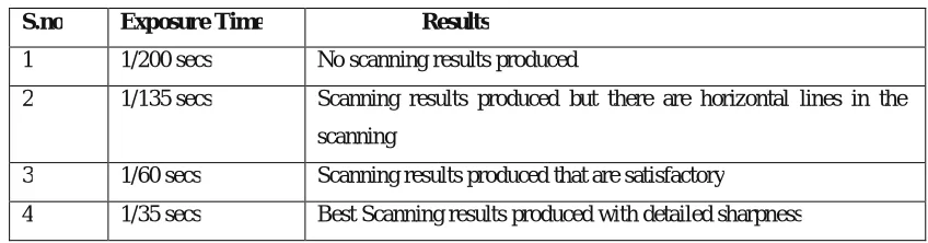
Exposure Time:
It is the time span when the camera is presented to light. The exposure time ought to be effect the scan quality. At the point when the exposure time is too high it will require greater time to record the scanning, all things considered to get the examining comes about the laser light ought to be moved gradually over the question be checked. when the exposure time is too low filtering outcomes heaps of undesirable output information. The presentation time ought to be set in order to give great filtering comes about.
Table 1: Exposure time and the results
S.no Exposure Time Results
1 1/200 secs No scanning results produced
The other scanning factor that greatly influences the scan quality is surface texture.
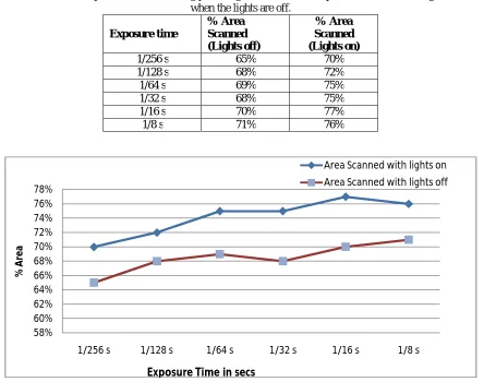
Laser Light Scanning for Shiny Surface:
The following table shows the value of the % area scanned when the room light is on.
Table 2: Shows the comparison of the scanning percentage area versus the exposure time when the lights are on and when the lights are off.
Exposure time
% Area Scanned (Lights off)
% Area Scanned (Lights on)
1/256 s 65% 70%
1/128 s 68% 72%
1/64 s 69% 75%
1/32 s 68% 75%
1/16 s 70% 77%
1/8 s 71% 76%
Fig. 2:Graph shows the comparison of the results when the lights are off versus when the lights are on.
From the above results it is clearly shown that the scanning results obtained are better when the lights of the room are kept off.
In this paper the various low cost scanning methods are discussed and their accuracy is compared so as to get the best scanning results with low cost.
Three different low scanning methods are visualized and compared so as to see which one produces the best scanning results. The three scanning methods that are discussed are as follows:
a) Manual Laser Light Scanning b) Semi automatic Laser Light Scanning c) Structured Light Scanning
58% 60% 62% 64% 66% 68% 70% 72% 74% 76% 78%
1/256 s 1/128 s 1/64 s 1/32 s 1/16 s 1/8 s
%
A
re
a
Area Scanned with lights on Area Scanned with lights off
Manual Laser Light Scanning:
In order to check the accuracy of the scan the cylindrical object is taken which is piston. Now the piston surface texture is shinny and the scan results of the shinny surface is not good due to the fact that the shinny surface reflects the light and the scanning results are wavy and the accuracy is also affected.
Fig. 3 (a) Shows the scanning results with the measured values (b) Shows the top view of the scanned data.
Now in order to make the surface opaque the surface of the piston is wrapped with white piece of paper. The results obtained are as shown above.
Semi Automatic Laser Light Scanning:
Structured Light 3D Scanning:
It is a standout amongst the most developed methods of scanning. This procedure utilizes video projector and camera for checking. The video projector is utilized to acquire the structure light and camera is utilized to catch the filtering of the question. In this checking technique a progression of fringe pattern comprising of interchange highly contrasting lines are made to fall on the object to be scanned. These projected fringe patterns are deformed as per the shape of the object. The camera is used to record the deformation of the fringe light pattern
Fig. 5 (a) Shows the experimental set up of Structured Light Scanning (b) Shows the scanning results obtained by Structured Light Scanning
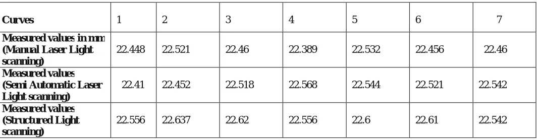
Table 3 : Shows the measured value obtained by all the scanning methods.
Curves 1 2 3 4 5 6 7
Measured values in mm (Manual Laser Light scanning)
22.448 22.521 22.46 22.389 22.532 22.456 22.46
Measured values (Semi Automatic Laser Light scanning)
22.41 22.452 22.518 22.568 22.544 22.521 22.542
Measured values (Structured Light scanning)
Fig.6: The graph plotted shows the comparison of scan results of all the three methods used to obtain the scan results.
IV. CONCLUSION
From the past investigation we presumed that the 3D checking is exceptionally helpful apparatus to make the 3D state of the segments from this present reality into mechanized frame as three dimensional portrayals. The 3d examining is generally utilized for Reverse designing purposes it helps in extricating the correct shape and size of the parts whose physical credits are hard to quantify and it is likewise broadly utilized for checking the nature of the segments which generally take long time. Specialists have likewise contemplated different checking techniques and different examining factors are considered which extraordinarily impact the nature of 3D filtering to filter the parts it is discovered that Laser Light Scanning and Structured light checking are broadly utilized as a part of figuring out and examination purposes as the outcomes deliver by these strategies are very exact.
REFERENCES
[1] ZHANG Z, “A flexible new technique for camera calibration.” IEEE Trans.Pattern Anal. Mach. Intell., pp 1330–1334(2000). 22.25
22.3 22.35 22.4 22.45 22.5 22.55 22.6 22.65 22.7
1 2 3 4 5 6 7
M
e
as
u
re
d
V
a
lu
e
s
in
m
m
Curves
Comparison of scan results for three scanning methods
Manual Laser Light Scanning
Actual Value
Semi Automatic Laser Light Scanning
[5] Song Zhang and Peisen S. Huang, “High-resolution, real-time three-dimensionalshape measurement.”Optical engineering, 123601, Vol. 25 (2006).
[6] Lanman Et al. ,“Surround Structured Lighting for Full Object Scanning.”3DIM '07 Proceedings of the Sixth International Conference on 3-D Digital Imaging and Modeling, pp. 107-116 (2007).
[7] Ali Peiravi, BehraiTaabbodi, “A Reliable 3D Laser Triangulation-based Scanner with a New Simple but Accurate Procedure for Finding Scanner Parameters” Journal of American Science, Vol. 6, pp. 80-85, (2010).
[8] Martinez Et al. , “Analysis of laser scanning and strategies for dimensionaland geometrical control”International Journal of Advance Manufacturing Technology, Vol. 46, pp. 621-629, (2010).
[9] I. Martynov, J.-K. Kamarainen, and L. Lensu, “Projector calibration by inverse camera calibration,” in Proceedings of the 17th Scandinavian conference on Image analysis, Berlin,Heidelberg, pp. 536–544,(2011).
[10] S.Y. Park, J. Baek, J. Moon, “Hand-held 3D scanning based on coarse and fine registrationof multiple range images”,Machine Vision and Applications, Vol. 22, pp. 563-579, (2011).
[11] Hafeez Anwar, Et al. “Projector Calibration for 3D Scanning Using Virtual Target Images”, Journal of Precision Engineering and Manufacturing, Vol. 13, pp. 125-131, (2012).
[12] KarimaOuji, Mohsen Ardabilian, Liming Chen, FaouziGhorbel, “3D Deformable Super-Resolution for Multi-Camera 3D Face Scanning”, Journal for Math Imaging Visualisation, Vol. 47,pp. 124-137,(2013).
[13] O. Aubreton, Et al. “Infrared system for 3D scanning of metallic surfaces”, Machine Vision and Applications, Vol. 24, pp 1513-1524,(2013). [14] Arnulfo León Reyes Et al. “Low cost 3D scanner by means of a 1D optical distance sensor”, International journal of Elsevier , procedia pp. 223-230 (2013).
[15] Huijie Zhao Et al. “Calibration for stereo vision system based on phase matching and bundle adjustment algorithm”,International journal of Elsevier , Optics and Lasers in Engineering, Vol. 68, pp. 203-213 (2015).
[16] Salvatore Gerbino, Et al., “On the influence of scanning factors on the laser scanner-based 3D inspection process”, International Journal of Advance Manufacturing Technology, Vol. 22, pp. 128-131, (2015).
[17] L.M. Galantucci, Et al., “Semi-Automatic Low cost 3D Laser scanning systems for reverse engineering” , International journal of Elsevier , procedia CIRP pp. 94-99 ,(2015).
[18] Yutao Wang and His-Yung Feng, “Effect of Scanning Orientation on outlier formation in 3D laser scanning of reflective surfaces”, International journal of Elsevier, pp.35-45, (2016).