ABSTRACT
CANSIZOGLU, OMER. Mesh Structures with Tailored Properties and Applications in Hip Stems. (Under the direction of Ola Harrysson (chair) and Denis Marcellin-Little (co-chair).)
The purpose of the research has been to develop mesh structures with tailored
properties for hip stems. Stress shielding is one of the crucial problems with current hip
implants due to the modulus mismatch between the bone and the hip stem. Solid titanium
or cobalt-chromium stems are changing the natural stress patterns in the femur. Stresses
are transferred through the hip stem and are concentrated more at the distal end of the
stem, which weakens the top portion of the femur and overloads the distal portion of the
femur. Stress shielding in the long term may result in implant failure due to bone loss,
which is costly and painful for the patient. Naturally, biomaterials have tailored structures
that display optimal behaviors under tensile, bending and other applied loads. Bones are
also tailored to the loading conditions and show stress patterns accordingly. This thesis
reports on the development of new hip implants where the mechanical properties of the
stems are tailored to match the bone’s properties using open cell structures and mesh
structures. Solid free form fabrication techniques are used in this thesis to manufacture
parts in the Electron Beam Melting (EBM) by Arcam AB, Sweden. This processing
method offers a unique way of making hip stems with mesh and solid sections together in
one build. Different designs of hip stems have been manufactured and tested. Their
affects on the bones have been analyzed and demonstrated using the Finite Element
Analysis (ABAQUS). Hip implants were tested on cadaver bones to measure the
difference between mesh stems and solid commercial hip stems. This thesis also includes
studies about the mesh quality under different processing conditions, and the applications
Mesh Structures with Tailored Properties and Applications in Hip Stems
by
Omer Cansizoglu
A dissertation submitted to the Graduate Faculty of North Carolina State University
in partial fulfillment of the requirements for the Degree of
Doctor of Philosophy
Industrial Engineering
Raleigh, North Carolina
2008
APPROVED BY:
Dr. Denis J Marcellin-Little Dr. Ola L.A Harrysson Co-Chair of Advisory Committee Chair of Advisory Committee
Dr. Denis Cormier Dr. Harvey A. West Advisory Committee Advisory Committee
DEDICATION
Without my grandma’s encouragement, I would have never gone to the primary
school in Turkey. My parents, Kezban and Mehmet, always supported me during my
education with undying sacrifices. My wife, Aysegul, helped to start and finish the PhD
and always support me on every subject. My sister, Serap, always helped me to find my
way in the undergraduate program at Bilkent University. My brother, Burak, helps me to
keep up the morale. My relatives always support me to pursue higher degrees. I dedicate
this work to all of them and to anyone who might benefit from it.
BIOGRAPHY
Omer Cansizoglu was born in Eskisehir, Turkey. He obtained his bachelor’s degree in
Industrial Engineering from Bilkent University in 2003. He was accepted to the Ph.D.
program at North Carolina State University after his BS Degree. He got interested in
rapid manufacturing and tissue engineering after a couple of graduate courses at NC State
University. He switched to the manufacturing concentration without prior experience. He
practiced with all the equipment and all the machines in Parkshop lab and learned the
practical manufacturing on his own. His advisors and their interesting projects motivate
him to pursue a PhD in this research area. He decided to include the structural
optimization into the rapid manufacturing area after learning about unit cell generation in
tissue engineering with topology optimization methods. He has developed hip stems with
tailored structures, which is a novel medical implant. His research interests include
structural optimization, rapid manufacturing, medical implants, manufacturing process
Acknowledgements
My sincere thanks go to my advisors, Dr. Ola Harrysson and Dr. Denis
Marcellin-Little, and to the other members of my Ph.D. committee at North Carolina State
University (NCSU), for their invaluable help and support during the entire research. I also
thank all the members of the Edward P. Fitts Department of Industrial and Systems
Engineering at NCSU, who were my great supporters during my doctoral study. I
acknowledge them for their continuous support and encouragement.
I appreciated the help from Dr. Peter Mente, Dr. Simon Roe, and Mr. Ryan
McCulloch for helping me to set up the implant testing.
Staff at Harnett county animal shelter was very friendly and helpful in bone
collection.
I acknowledge my friends Tushar Mahale, Kyle Knowlson, Daniel Brooks,
Dimitrios Makrozahopoulos, Engin Murat Reis, Merivan Tunc Reis, Murat Erenli,
Canguzel and Fahir Zulfikar, Mustafa Bakkal, Hilmi Aydin, Evren Tipi, Bugra Akben,
TABLE OF CONTENTS
List of Tables ... vii
List of Figures ... viii
1. Introduction... 1
2. Mesh Structure Development ... 6
2.1. REVIEW OF MESH STRUCTURE MANUFACTURING ... 6
2.1.1. Plasma Spray ... 8
2.1.2. Combustion synthesis ... 8
2.1.3. Powder metallurgy ... 9
2.1.4. Electrical Discharge Compaction ... 9
2.1.5. Plastic mold techniques ... 10
2.1.6. Wire Mesh ... 10
2.1.7. Vapor deposition ... 10
2.1.8. Orientation with Magnetic field ... 12
2.1.9. Chemical Etching ... 13
2.1.10. Selective laser sintering ... 15
2.1.11. Direct metal laser sintering (DMLS) ... 15
2.1.12. Laser Engineered Net Shaping ... 16
2.1.13. Microsintering ... 18
2.1.14. 3D printing ... 19
2.1.15. 3D fiber deposition... 21
2.1.16. Electron Beam Melting ... 21
2.2. MECHANICAL BEHAVIOR OF METALLIC FOAMS ... 27
2.3. INITIAL HEXAGON MESHES ... 35
2.3.1. Design and Fabrication of Structures ... 38
2.3.2. Compression Test Procedure ... 39
2.3.3. Flexural Test Procedure ... 40
2.3.4. Experimental results ... 41
2.3.5. Finite element modeling ... 46
2.3.6. Discussion ... 47
2.3.7. Conclusions and Future Directions ... 49
2.4. RHOMBIC STRUCTURES ... 50
2.4.1. EBM Manufacturing ... 52
2.4.2. Testing ... 52
2.4.3. Analysis and FEA ... 53
2.4.4. Compression Testing ... 54
2.4.5. Flexure Testing ... 57
2.4.6. Discussion and Conclusions ... 58
2.5. MELTING EFFECTS ON MESH STRUCTURES ... 60
2.5.1. Structure Design ... 60
2.5.2. Manufacturing ... 61
2.5.3. Mechanical testing ... 62
2.5.4. Results and Discussion ... 62
3. Applications of Structural Optimization ... 66
3.1. TOPOLOGY OPTIMIZATION ... 66
3.1.1. Results from topology optimization ... 74
3.2. MESH BASED OPTIMIZATION ... 79
3.3. OPTIMIZED MESH STRUCTURES ... 81
3.3.1. Design of structures ... 81
3.3.2. Optimization of structures ... 83
3.3.3. Fabrication of structures ... 90
3.3.4. Testing of structures ... 91
3.3.5. Discussion ... 93
3.3.6. Conclusion ... 95
4. Design and fabrication of hip stems ... 96
4.1. HIP IMPLANT SYSTEMS ... 96
4.2. BONE REMODELING... 101
4.2.1. Bone Remodeling Models ... 102
4.3. DESIGNS TO PREVENT STRESS SHIELDING ... 104
4.3.1. Different geometric designs ... 104
4.3.2. Composite stems ... 109
4.4. PATENTS RELATED TO REDUCED STRESS SHIELDING... 115
4.5. METAL MESH STEMS ... 116
5. Biomechanical Testing of stems ... 124
5.1. IN VITRO TESTING ... 127
5.1.1. Overview ... 127
5.1.2. Materials and Methods ... 127
5.1.3. Results and Discussion ... 132
5.1.4. Conclusion ... 134
6. Conclusion and Future Work... 136
7. References... 138
8. Appendix ... 150
8.1. APPENDIX 1 ... 151
8.2. APPENDIX 2 ... 152
LIST OF TABLES
Table 1: Cell type and some of the manufacturing methods are listed. ... 7
Table 2: Some of the companies related with laser fabrication process. Source: (Santos, Shiomi et al. 2006), reprinted by permission from Elsevier. ...15
Table 3: Summarizes compression test results for 4 mm, 5 mm and 6 mm structures. ...43
Table 4: Bending test results ...46
Table 5: Compression testing of rhombic structures with cell sizes from 3 mm to 12 mm. ...55
Table 6: Comparison of tested structures and simulated structures with 0.49 mm2 square profile beams. ...57
Table 7: Bending test results for 3mm, 6mm, and 8 mm structures ...58
Table 8: Melting parameters for 3 sets of mesh structure samples ...61
Table 9: Beam thicknesses and comparison to the max force ...65
Table 10: Compliance ratios in testing and FEA for updated coordinates and thicknesses ...92
Table 11: Material combinations and wear rates. SOURCE : (Semlitsch and Willert 1997) ...97
Table 12: 800N measurement of 9 paired samples ... 133
Table 13: 1600N measurement of 6 paired samples ... 134
Table 14: List of Cadaver Bones ... 151
Table 15: Cadavre surgery notes ... 152
LIST OF FIGURES
Figure 1: Trabecular Metal (Zimmer,Inc, Warsaw, Ind previously Hedrocel, Implex
Corp.), (Bobyn, Stackpool et al. 1999),Reprinted by permission from the author. ...11
Figure 2: Low relative density honeycomb core manufacturing (Wadley, Fleck et al. 2003), Reprinted by permission from Elsevier. ...12
Figure 3: Magnetic field applied while filling the cavity. Source: (Chino, Mabuchi et al. 2006) ,Reprinted by permission from Elsevier. ...13
Figure 4: Structure of the multilayered mesh surface. (a) Pattern design and (b) Laminations. Source: (Kusakabe, Sakamaki et al. 2004), Reprinted by permission from Elsevier. ...14
Figure 5: 3D mesh structures in stainless steel and in cobalt-chrome Source: http://www.mcp-group.com/rpt/rpttslm_1.html reprinted by permission from the MCP-group.com ...16
Figure 6: OPTOMEC ,medical device fabrication. Source: http://www.optomec.com, LENS®, reprinted by permission from Optomec. ...17
Figure 7: Parts from the LENS process. Source: (Wu and Mei 2003) reprinted by permission from Elsevier. ...18
Figure 8: Powder deposition with adjustable layer thickness and density. Source: (Haferkamp, Ostendorf et al. 2004) reprinted by permission from Elsevier. ...19
Figure 9: 3D printer (Curodeau, Sachs et al. 2000) , Copyright © 2000. Reprinted by permission of John Wiley & Sons, Inc. ...20
Figure 10 : Different surface texture geometries and surface image of the castings (Curodeau, Sachs et al. 2000) , Copyright © 2000. Reprinted by permission of John Wiley & Sons, Inc. ...21
Figure 11: Sketch illustrated the Beam control system Source: EBM manual ...22
Figure 12 : Electron beam is melting the current layer (CoCr test parts in EBM S12) ...25
Figure 13: EBM build platform with sintered powder surrounding the actual parts. ...25
Figure 14: Compressive stress-strain curve for 6101 Al foam (9.2% density), (Nieh, Higashi et al. 2000) reprinted by permission from Elsevier. ...28
Figure 15: a) M<0 and it is a bending mechanism b) M=0 and It is stiff with horizontal beam in tension c) M>0 and it is over-constrained. ...29
Figure 16: A stress-strain curve of a cellular solid with typical densification. ...31
Figure 17: Structures with straight holes were manufactured using EBM...32
Figure 18: Less stiff implant designed with straight holes. ...33
Figure 19: Edges of Honeycomb are intertwined to other layer in variable porosity ...33
Figure 20: Titanium solid model of the honeycomb design made with EBM. ...34
Figure 21: Flexible implant example from different views. ...34
Figure 22: a) beam thickness is shown before slicing of the beam b) Overlaps, defined as L1-L2, between successive layers are shown with the related parameters. ...36
Figure 23: Close up view of Strut Qualities from earlier samples...36
Figure 24: Range of Strut Qualities for same beam melting parameters at same micrograph scale a) 20°, b) 30°, c) 40°, d) 50°, e) 60°, f) 70°, g) 80° angle with respect to XY plane ...37
Figure 26: Compression Specimens with 2mm (not tested),3mm (not tested),4 mm, 5 mm, and 6 mm Unit Cell Dimensions. ...39 Figure 27: Compression test was done using parallels at each face for 4mm, 5mm and 6mm cell sizes ...40 Figure 28: Compression Test Results for 4mm structures with maximum loading up to 5500N ...42 Figure 29: Compression Test Results for 5mm structures with maximum loading up to 2400 N ...42 Figure 30: Compression Test Results for 6mm structures ...43 Figure 31: Comparison of tested and estimated results A) Compressive strength as a function of relative structure density B) Elastic modulus (E) as a function of relative structure density ...45 Figure 32: a) two copies each of three different bend specimens with cell sizes of 4 mm, 5 mm and 6 mm b) Flexural testing ...45 Figure 33: Elastic modulus (E) versus relative density for different builds of specimens. Each build has 2 copies of each unit size of long beams. Data points are average of each build sets for each cell sizes. ...46 Figure 34: a) Simulated FEA results for different beam thickness of different cell sizes b) Comparison of ANSYS results and Testing results in scaling ...47 Figure 35: SEM picture of Lattice structure is showing the unmelted powder attached to the beams. ...48 Figure 36: SEM picture of the crushed lattice structure is shown with sintered Ti64 powder particles. ...48 Figure 37: a) Relative dimensions of one face of the rhombic dodecahedron unit cell b) front view of the unit cell c) rectangular flexural test bar with rhombic dodecahedron unit cells ...50 Figure 38: Principal fabrication of thin struts using layered fabrication technology. ...51 Figure 39: Structures fabricated via Electron Beam Melting: a) Cubes with 40% relative density (60% porous) b) Cubes with relative densities of 8.0%, 5.0%, and 3.8% c)
Bending specimens with 8 mm and 6 mm cell sizes (7.3% and 11.9% relative density) ..52 Figure 40: Three point flexure testing of rectangular mesh beam ...53 Figure 41: ANSYS simulated mesh structure...53 Figure 42: a) Average compression strength versus relative density for tested and
Figure 48: Molds and sintered final parts. (Hollister, Maddox et al. 2002) with permission
from Elsevier. ...69
Figure 49: Porosity level 49% for mandibular condyle (Lin, Kikuchi et al. 2004) reprinted with permission from Elsevier. ...71
Figure 50: Porosity level 35% for mandibular condyle (Lin, Kikuchi et al. 2004) reprinted with permission from Elsevier. ...71
Figure 51: Design domain and resulted optimal topology with support design method, (Buhl 2002) reprinted with permission from Elsevier. ...73
Figure 52: SEM photo of 3D compliant mechanism and experimental measurement set up, (Huang and Lan 2006) with permission from IOP publishing. ...74
Figure 53: Left side of the material boundary was fixed and loading was at right bottom corner in -Fx and Fy direction. Volume reduction is constrained to 50% with 60 iterations. ...75
Figure 54: Volume reduction is constrained to 75% with 20 iterations. ...75
Figure 55: 3D volume topology optimization example. Force is applied at the bottom corners. Structure volume reduced to 50% of initial boundary volume. Left are density readings in the boundary. Right is one slice showing the cross section density. ...75
Figure 56: Selected elements based on density of 0.9. Zero density means void. ...76
Figure 57: Mitchell type test part original and simplified ...76
Figure 58: Original structure and final structure with element densities in the topology optimization modules (ANSYS). ...77
Figure 59: Outside nodes of the selected elements which have densities between 0.4 and 1. ...77
Figure 60: Geomagic point processing to make surfaces for this 2D part. ...77
Figure 61: Magics stl file fixing for RP process. ...78
Figure 62: Some of the features are recognized in SolidWorks ...78
Figure 63: Final Mitchell structure made from Ti6Al4V powder using the EBM S12. ....79
Figure 64: a) 10 vertices are defined for each beam and 2 of them are actual nodal points. b) Two beams are shown without additional cube at intersection. ...82
Figure 65: a) Original STL-file of two dimensional truss beams constructed from FEA truss elements b) stl-file of simplified two dimensional truss beam ...83
Figure 66: 2D cantilever beam example ...86
Figure 67: a) Original 3D grid with dimensions of 20 x 20 x 20 mm b) Analysis output structure in 3D beams c) Output structure as STL-file format. ...87
Figure 68: a) 3D grid with the dimensions 20X20X20 mm b) Solution output structure in beam elements c) Output structure as STL-file format (Figures are not at same scale) ....88
Figure 69: a ) Overall dimensions of the structure are 12 mm in Z and 10.4 mm in X and Y, where a=1.5 and b=a/tan(30), b) Input 3D lattice structure in MATLAB, c) Output 3D lattice structure in the STL-format ...89
Figure 70: Compliance and constraint history of rhombic structures for 200 iterations ...89
Figure 71: a) 2d cross sections for initial implant mesh b) after node movement cycle in 2d beam plots c) initial structure in Magics, and d) output structure in Magics ...90
Figure 72: Optimized and original structures fabricated using an SLA 190 and EBM ...91
Figure 74: a) Cube grid 2, EBM part, for loading in x direction (shear) ratio is 1459.1/390.31=3.73. b) Cube grid 1, EBM part, in compression loading ratio is 2.52 (beams are ~2mm) ...92 Figure 75: Load and displacement after structures contacted the loading plates entirely. Optimized over original stiffness ratio is 1.71...93 Figure 76: a) A thin low angled beam structure fabricated using the EBM technology b) effect of low build angle on thin beam structures structure ...94 Figure 77: A cervico-trochanteric prosthesis: (a) inner side, (b) outer side, and (c)
Figure 94: Hip stem with bone ingrowth meshes and reference features for finishing. .. 123
Figure 95: Strain gages at five levels are shown at heel strike loading set up, (Waide, Cristofolini et al. 2003), reprinted with permission from Elsevier. ... 125
Figure 96: Left) Hip stems were aligned vertically at 10° with using impaction hole in the stem, and Right) aligned horizontally with reference to the screws on the alignment fixture. ... 128
Figure 97: Four strain gages were attached at the bending direction and one is at the same level at strain gage-2 opposite direction ... 129
Figure 98: Example test set up which shows 4 strain gages, (Munting and Verhelpen, 1995) ... 130
Figure 99: In Vitro testing set up for hip stems. ... 130
Figure 100: Close up view of implant head and cup in a testing set up. ... 131
1. INTRODUCTION
Osteoarthritis (OA), rheumatoid arthritis (RA), avascular necrosis, and trauma
may cause defects at the cartilage. OA alone indicates the degeneration of articular
cartilage together with the changes in the subchondral bone and mild intraarticular
inflammation. A number of environmental risk factors, such as obesity, occupation, and
trauma, may initiate various pathological pathways (Sarzi-Puttini, Cimmino et al. 2005).
Severe defects in cartilage lead to pain and loss of joint function. Hip implants are used
to replace the socket and head of the femur with artificial components, when surgery is
the only option. There are also alternative treatments for different stages of the defects in
cartilage such as cartilage replacement, surface replacement of the femoral head, and pain
reducing drugs for early stages. Cartilage replacement is still at infancy. Tissue
engineering has been used, but cell selection, scaffold design and biological stimulation
are the current challenges of cartilage replacement. Drugs are used to adequately control
pain, improve function, and reduce disability when applicable.
Hip implants have been used since the 18th century (Scales 1966). The Rigid
fixation method became popular with Charnley’s technique (Charnley 1960). Charnley’s
technique has a very high rate of success in the older population (Madey, Callaghan et al.
1997). However, a lower success rate has been reported for younger patients. The average
implant life time is 10 to 15 years and depends on the patient, implant type, fixation
methods, and materials. Ultra High Molecular Weight Polyethylene (UHMWPE) is still
used in the acetabular cup of hip implants today, but new materials have been studied
version of this material has also been developed to solve the wear problem in UHMWPE.
Structure, morphology, and mechanical properties of the polymer have been studied at
different stages of the production (Kurtz, Muratoglu et al. 1999). Metal-on-plastic
combinations have been widely used in the industry. Alternative combinations are a
ceramic head on a ceramic cup, a metal head on a metal cup, and a metal head on a
ceramic cup. New material development is continuing to decrease the wear rate in hip and
knee implants.
Cementless implants have been developed as an alternative to cemented implants.
In cementless implants, the implant surface is coated with metal beads, meshes, or fine
particles for bone ingrowth. Implant loosening was associated with the cement in the
literature and studies have focused on porous coatings. Different manufacturing methods
have been tried to get good surface adhesion between bones and implant coating.
The differences in patient anatomy are important for cementless implants, and the
surgeon has to make sure that the implant is positioned firmly to assure good initial
fixation for bone ingrowth. Long term success is related with the fit between implant and
bone. Modular implants have been developed to provide flexibility in the options
available for each bone. In modular implant systems, different sizes of the stem, head, and
acetabular cup can be used to improve the fit between implant and bone. Modular
implants with too many components are not acceptable to surgeons. Each additional
component is creating a risk of extra metal wear particles and this is related to widely
known problems. Implants are expected to stay in the body for a long period of time, so
implant performance is important to avoid revision surgery. A new era of implants has
been started with a customization of implants to the patients. Customization of implants
manually bending and fitting the plates to the bone to have a good fit at the interface
(Imatani, Ogura et al. 2005). High tech methods have enabled surgeons to just use the
customized implants designed and manufactured before the surgery without manual
adjustments. Customization of the implants to each patient has been successfully done
with the help of 3D imaging software and new manufacturing techniques.
Another problem with implants is that the stiffness between bone and implant are
mismatched. Titanium hip stems have a modulus of 110 GPa, while the modulus of the
bones are 15-20 GPa. The increase in the stiffness of the implant creates more stress
shielding. Cobalt chrome stems have higher modulus than titanium stems and also
increased stress shielding. Metal stems distort the loading mechanism of the bone.
Stresses around the femur change with stiff stems, which is explained in the next sections.
Rigid hip implant stems result in less load transfer proximally leading to the stress
shielding of the proximal femur. A decrease in stress levels around the bone will decrease
the density of the bone, which will make it more susceptible to failure. Lower stiffness
material will transfer the load more proximally, but it will result in higher load transfer
stresses at the bone and implant interfaces with the risk of interface failure. Implant
micromotions will increase with a more flexible implant. There is a trade off between
stress shielding and implant failure. Many studies have analyzed different geometries and
materials to solve these discussed problems. Femur head replacement has been tried
instead of inserting a solid stem into the femur with a low success rate. Femur head
replacement is also limited to special cases. Composite hip implants and modular hip
implants have been tried without much success. Different hip implant designs have also
been studied to reduce the stress shielding. Different implants with lower stiffness have
element analysis (FEA), and also in testing. The degree of flexibility of the implant
depends on the bone density of the patient, which changes according to the age, activity
level, hormone level and so on. Therefore, each bone will require different implant
geometries and implant mechanical properties.
With the advent of the Rapid Prototyping (RP) technologies, each patient’s bone
properties can be used to design an optimal hip implant. This multidisciplinary work will
include the design, analysis, manufacturing, and testing of the hip stems. Hip stems will
be manufactured with internal structure out of titanium. The hip implants will be designed
using Mimics (Materialise, Belgium), MAGICS X and Solid Works 2005. An internal
structurewill be designed to match the desired stiffness at different sections. Initially,
grooves and holes will be designed and optimized with design analysis in ANSYS
according to the required stress and strain energy levels. Internal mesh structures will be
designed according to the material properties of the metal and the bone. Design iterations
will be evaluated in FEA using ANSYS. Mechanical tests will be done for manufactured
representative blocks and hip stem alternatives. Stress and strain levels around the
implant will be measured for different designs. Electron Beam Melting (EBM), 3D
Printing (Zcorp,MA,US), Fused Deposition Modeling (FDM) processes will be used to
build models for visual inspection and functional testing. Final implants will be
manufactured with bone in-growth surfaces using a minimum number of steps, which is
revolutionary compared to the current manufacturing techniques for implants. The top
and bottom surfaces of the implant will be CNC machined in a 4-axis milling machine for
final dimensions. In a future study, clinical trials will be done for successful designs and
developed topological design methods and manufacturing techniques will be applied to
other implants and other areas which require the development of tailored part properties.
This thesis combines RP technologies and design optimization methods to develop
and manufacture hip stems with custom flexural modulus.. The long term goal will be to
use the combination of solid free form fabrication and topological design optimization.
This goal will have a higher impact on increasing the efficiency of the products. Product
weight and performance will be designed optimally and complex RP processes will be
capable of fabricating those products by satisfying the process specific constraints. 2D
and 3D structures with customized mechanical properties will be possible with layout
optimization methods and RP. Recent examples of the method and details about hip stems
are given in the next sections.
2. MESH STRUCTURE DEVELOPMENT
Metal foam and metal lattice structure manufacturing methods are related to this
study. Some manufacturing methods especially related to open cell structures are
reviewed in this section.
2.1.
Review of mesh structure manufacturing
Homogenous porous systems have been fabricated using many different methods.
Porous metallic systems can be divided into closed cell and open cell structures. Closed
cell foams are usually resulting from random foaming processes. Porous material
properties are controlled by the pore size, shape and pore distribution (Brothers and
Dunand 2006). Energy absorption is one of the primary applications of porous metal
structures. Rabiei et al. developed a new composite metal foam which uses hollow
spheres that are packed into random order and infiltrated with an aluminum alloy (Rabiei
and O'Neill 2005). This foam showed superior compressive strength that averaged around
67MPa and good energy absorption. Their recent work about Al-steel composite cast
foam at relative density of ~42% showed plateau stresses of 50-90MPa and a
strength/density ratio of 21-37 (Vendra and Rabiei 2007).
Various fabrication processes have been developed to produce porous metallic
Table 1: Cell type and some of the manufacturing methods are listed.
Cell type Method
Closed Gas Injection
Closed Decomposition of
foaming agents
Open Sintered metal powders
Open Sintered metal fibers
Open Space holder method
Open Replication
Open Combustion synthesis
Open Plasma spraying
Open Oriented wire mesh
Open Vapor deposition
Open Rapid Prototyping
Open Electro discharge
compaction
Some of the processes such as casting or vaporous deposition have more control
over pore size, interconnection and distribution, while other processes such as
decomposition of foaming agent result in more random pores. Challenges for porous
materials besides pore size control are fatigue strength (Yue, Pilliar et al. 1984;
Crowninshield 1986) and corrosion (Jacobs, Gilbers et al. 1998). Some of the processes
2.1.1. Plasma Spray
Plasma spraying can be used to create varying porosity in the surfaces (Ryan,
Pandit et al. 2006). It has been used to create 3 different layers of surface coating for
implants. Yang et al. prepared graded porous coatings by regulating the spraying power
and the content of Ti powder (Yang, Tian et al. 2000). Small particles melted and formed
the dense region, while large particles partly melted and formed the macro pores.
Mechanical, physical and metallurgical bonding between the Ti substrate and coating was
observed. Sandblasting treatment was observed to increase the mechanical bonding. The
physical attraction between the Ti substrate and the coatings was also observed. A
reducing working atmosphere helped to reduce the oxide layer thickness, which helped
with the direct contact of powder and base. The porous coating was prepared as a dense
layer near the surface of the substrate, micro pores at the middle, and macro pores at the
outside.
2.1.2. Combustion synthesis
Combustion synthesis has been used to produce metallic foams. Reactants are
mixed and cold pressed. Samples are placed in an inert atmosphere and ignited to start the
thermal explosion mode or self-propagating high thermal synthesis. Zhang X et al. used
combustion synthesis to produce porous surfaces that resulted in bone ingrowths without
an immune response (Zhang, Ayers et al. 2001). One of the process advantages was high
purity of the foams. Kanetake et al. synthesized nickel aluminide foam and porous Ti
composite (TiC, TiB(2)/Ti) (Kanetake and Kobashi 2006). An exothermic reaction
the porosity, foaming agents were mixed with the base powders before the reaction.
Effects of the different blending ratios were observed on the pore morphology. Porosity
of the precursor also affected the pore morphology. Open pore structures were obtained
by using a low titanium blending ratio and highly porous initial compacted material.
Closed pores were obtained with higher Ti/B4C ratio, which increased the fluidity of Ti
and tendency to form spherical pores with surface tension.
2.1.3. Powder metallurgy
Powder metallurgy is a common technique for producing cellular structures.
Porosity is the natural result of the process. For dense parts, parts manufactured by
powder metallurgy are infiltrated with other materials to fill the porosity. Porosity levels
can be increased by adding blowing agents. The mixture is compacted to get a semi
finished product. After that, it is heat treated near the melting temperature of the matrix
material. The blowing agent releases gas while the matrix is at the elevated temperature.
These methods are suitable for Al, Zn, and Mg foams but Ti foams are unsuitable due to
the high melting point temperature and reactivity. Conventional sintering of titanium
alloy powders requires high temperatures in high vacuum for a long period of time. Wen
and coworkers have fabricated titanium foams by using a Powder metallurgical process
including space holder particles (Wen, Yamada et al. 2002). Densities of the titanium
foams were approximately 50-65% which is close to cortical bone.
2.1.4. Electrical Discharge Compaction
As sintering of titanium is difficult, new alternatives have been studied for porous
titanium alloys. Electrical discharge compaction (EDC) has been used to fast sinter
discharging capacitors. Qiu and coworkers fabricated composite titanium dental implants
with electro discharge compaction (Qiu, Dominici et al. 1997). Lee et al. reported that
porous implants produced by EDC are biocompatible and allow rapid osseointegration
(Lee, Park et al. 2000).
2.1.5. Plastic mold techniques
Molds are prepared from polyurethane type material foams and coated with
metallic slurry. The polyurethane is removed by heating slowly and pressure is sometimes
applied to keep the structure intact. After removing the molding foam, it is sintered.
Molds can be in different shapes. Li et al. used polyurethane struts as a mold and coated
them with a titanium slurry (Li, Wijn et al. 2006). After removing the polyurethane, the
powder was sintered. The porosity of the porous titanium alloy was 88% with a
compressive strength of 10 MPa.
2.1.6. Wire Mesh
Wires can be randomly put together to get meshes or they can be oriented to get
woven structures. Naidu et al. developed orderly oriented wire mesh (OOWM) structures
as an alternative to porous beads and fiber meshes (Naidu, Moulton et al. 1997). Wires
are woven into a regular meshwork and pressure sintered to the surface. Mechanical pull
out tests were done at 4 weeks, 8 weeks, and 12 weeks after implantation. OOWM was
reported to be as effective as porous beads in bone ingrowths and stability.
2.1.7. Vapor deposition
A carbon skeleton was obtained from the thermosetting polymer foam,which has a
changes the pore size and mechanical properties of the Trabecular Metal® as shown in
Figure 1. The tantalum deposited into the carbon skeleton using chemical vapor
deposition with 50μm coating thickness. Deposition thickness affects the pore size and
mechanical properties. Textured microstructures are the result of this process due to the
orientation during deposition and crystallographic growth. Average pore diameter was
around 547 μm with 75-80% homogenous porosity. The Trabecular Metal® was
approved by the FDA in 1997 as a bone ingrowth material. Trabecular Metal® has been
reported to have good mechanical properties with an elastic modulus of 3 GPa (Bobyn,
Stackpool et al. 1999). This is reasonably similar to cancellous bone (0.1-1.5 GPa). In
contrast, cortical bone has an elastic modulus of 12-18 GPa (Medlin, Charlebois et al.
2004) .
Figure 1: Trabecular Metal (Zimmer,Inc, Warsaw, Ind previously Hedrocel, Implex Corp.), (Bobyn, Stackpool et al. 1999),Reprinted by permission from the author.
Sandwich panels can be assembled from the metal foams using metal face sheets
(Banhart 2000). Wadley and Fleck et al. reported another way for sheet forming of trusses
and shell elements with periodic open cell pores (Wadley, Fleck et al. 2003). Low density
metallic honeycomb cores were manufactured from corrugated sheets and bonded
Figure 2: Low relative density honeycomb core manufacturing (Wadley, Fleck et al. 2003), Reprinted by permission from Elsevier.
2.1.8. Orientation with Magnetic field
Preferred orientation induced by a magnetic field is applicable to ferromagnetic
metal fibers, but there are limitations in controlling the structure. Chino et al. used a static
magnetic field to control porous structures in a restricted way (Chino, Mabuchi et al.
2006). Ferromagnetic metal fibers were cut with chatter vibration cutting tools. A
magnetic field was applied while filling the carbon die with fibers as shown in Figure 3.
It was shown that fibers lined up parallel to the direction of a magnetic field, so oriented
green compaction was made in the die. Higher collapse stress was observed with a
Figure 3: Magnetic field applied while filling the cavity. Source: (Chino, Mabuchi et al. 2006) ,Reprinted by permission from Elsevier.
2.1.9. Chemical Etching
Besides creating the porosity by controlling the process parameters, new methods
have been studied to control the mesh geometries with the design. Intended surface
structures have been designed and manufactured. Kusakabe et al. studied a new type of
porous coating for hip prostheses called ‘‘multilayered mesh’’ and tested under
weight-bearing conditions (Kusakabe, Sakamaki et al. 2004) as shown in Figure 4.
Hydroxyapatite (HA)-coated multilayer meshes resulted in more bone ingrowth than the
Figure 4: Structure of the multilayered mesh surface. (a) Pattern design and (b) Laminations. Source: (Kusakabe, Sakamaki et al. 2004), Reprinted by permission from Elsevier.
The multilayered structure provided a permanent bonding between bone
ingrowths and the surface structure. A 3D pattern was obtained from 2D layer titanium
meshes created by chemical etching. Ten layers of 100μm thick titanium 2D meshes
were bonded by heat process at 900°C. The porosity of the structure was around 80%.
Hydroxyapatite was applied to the surface by thermal spraying at 3000°C. Multilayers
were heated to 650°C in a vacuum furnace to release the residual stress. The HA coating
did not alter the pores or the uniform distribution. The HA coating was added for
increased chemical bonding to bone. A textured surface of multilayered mesh was
thought to be required for a long lasting support. The multilayered structure was
observed to be more resistive to shear forces and tensile forces than bead-coated implants
(Bellemans 1999).
RP systems are other alternatives to building controlled mesh structures. Many
different RP processes are available today to build dense metal parts. Direct metal
fabrication processes are of interest to this work. It is also possible to use indirect metal
difficult to do investment casting with prototyped plastic molds. Focus will be on the
direct fabrication for its efficiency and controlled properties. Some of the metal based
systems are 3D welding, jet solidification, shape-deposition manufacturing, laser based
systems, electron beam melting, spray metal, and 3D printing. The most popular systems
are laser systems and different types of laser based systems have been developed. Some
of them are given in Table 2.
Table 2: Some of the companies related with laser fabrication process. Source: (Santos, Shiomi et al. 2006), reprinted by permission from Elsevier.
2.1.10. Selective laser sintering
A roller mechanism is used to spread the powder over the build platform and each
layer is selectively bonded by the CO2 laser beam. The fabrication platform is lowered,
new powder is delivered, and the process repeats until the build is finished (Kruth, Wang
et al. 2003). The metal powder is mixed with a polymeric binder, so the laser energy
binds the particles as a green part, which needs secondary processing of sintering and
infiltration. When sintering is completed, the resulting part is porous and infiltration with
a metallic or polymeric material may be required.
2.1.11. Direct metal laser sintering (DMLS)
DMLS uses a powerful CO2 laser of 200W and directly sinters the metal powder.
mesh structures from the direct metal laser sintering are given in the Figure 5.
Three-dimensional mesh structures in stainless steel and in cobalt-chromium were built with
DSLM technology and resulted in nearly 90% reduction in weight. It is also applied in
dental applications for low volume production of dental caps.
Figure 5: 3D mesh structures in stainless steel and in cobalt-chrome Source: http://www.mcp-group.com/rpt/rpttslm_1.html reprinted by permission from the MCP-group.com
EOS GmbH (Munich, Germany) has a machine called the EOSINT M 270. It has
a Yb-fibre laser of 200W with precision optics. The build speed (material-dependent) is
given from 2 to 20mm3/s and the layer thickness is from 0.0254 to 0.1 mm. Direct part
and direct tool applications have been done for industrial applications.
2.1.12. Laser Engineered Net Shaping
A high power laser, 500-1000W, is used to melt the metal powder. The laser beam
gas may also be delivered through the same head while melting the powder. The head is
moved in the Z direction instead of moving the platform. Sandia National Laboratory
developed the laser engineered net shaping (LENS®). It is primarily useful for repair
operations, because it does not use a powder bed as is shown in the figure below. It has
other advantages such as hybrid manufacturing (www.optomec.com). It is possible to add
wear resistant materials or other types of materials locally. LENS®1 has been
commercialized through OPTOMEC (Albuquerque, NM) and different powder materials
have been developed for this process.
Figure 6: OPTOMEC ,medical device fabrication. Source: http://www.optomec.com, LENS®, reprinted by permission from Optomec.
Wu and Mei have manufactured Ti alloys and SiAl alloy onto Ti-6Al-4V alloy
(Wu and Mei 2003). The laser power ranged from 180 to1200W with a scanning rate of
150 to1000 mm/min. Test structures were built with overhanging features and thin
sections as shown in Figure 7. Ti-6Al-4V alloy has been reported to have a narrow
window for the processing parameters, and it is easy to form a porous microstructure.
Figure 7: Parts from the LENS process. Source: (Wu and Mei 2003) reprinted by permission from
Elsevier.
2.1.13. Microsintering
Small scale structures were built with the microsintering process using layer
resolutions at the micro level. 3D-Micromac AG, (Chemnitz, Germany) offers
microsintering technology to fabricate freeform micro parts. Micrometer resolution is
possible with a surface roughness of 1.5μm. The density of the micro parts made from
powder mixtures is around 95%. Haferkamp et al. developed a microsintering system
with a density controlled deposition mechanism as shown in Figure 8 (Haferkamp,
Ostendorf et al. 2004). The layer thickness has been reported to be in the range of
Figure 8: Powder deposition with adjustable layer thickness and density. Source: (Haferkamp, Ostendorf et al. 2004) reprinted by permission from Elsevier.
2.1.14. 3D printing
Recently, 3D printing has been used to produce porous implants with controlled
size, shape and distribution of porosity. Three-dimensional printing is a solid freeform
fabrication technique that can generate complex geometries from different materials layer
by layer as seen in
Figure 9. Melican et al. used 3D printing to prepare the molds with a dimensional
resolution of 175 μm (Melican, Zimmerman et al. 2001). Bone ingrowth surfaces were
produced from the textured surfaces of the molds and three experimental textures were
fabricated with the surface layer and the deep layer at different porosity ratios. Surfaces
of commercially sintered beaded coatings were used as controls. A canine transcortical
implant model was used in the study. Mechanical push-out tests were used to test the
interfacial shear strength at periods of 6, 12, and 26 weeks. Three textured surfaces were
evaluated and reported to have significantly higher shear strength at 26 weeks than the
controls. The relation between bone ingrowth and the level of porosity was discussed for
Curodeau et al. produced sub-millimeter surface textures with overhangs and
undercut geometries as bone ingrowth surfaces for implants (Curodeau, Sachs et al.
2000). Three-dimensional printing, as shown in Figure 10, is used for ceramic molds of
alumina powder with silica binder. Surfaces were textured with 5 layers of different
geometries with an overall porosity from 30 to 70%. Features as small as 350 x 350x 200
µm were successfully cast (Figure 10). Removal of the powder from the ceramic molds
and the required pressure to fill these small features with metal limited the possible
feature sizes.
Figure 10 : Different surface texture geometries and surface image of the castings (Curodeau, Sachs et al. 2000) , Copyright © 2000. Reprinted by permission of John Wiley & Sons, Inc.
2.1.15. 3D fiber deposition
Three dimensional metal structures can be created through extrusion. The metal
slurry can be prepared at different concentrations and compositions to adjust the viscosity
and the cured density of the extruded line. Li et al. prepared a porous Ti6Al4V scaffold
by extruding a titanium slurry (Li, Wijn et al. 2006). The external shape and the
interconnections were controlled while building the part. Ti6Al4V powder was mixed
with methylcellulose and stearic acid (34 vol%). The slurry was stirred for 1hr and then
extruded using a syringe under pressure. The deposited fibers were sintered in a high
vacuum furnace while applying heat up to 1250 °C.
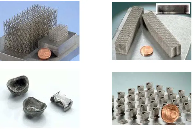
2.1.16. Electron Beam Melting
layers together with an electron beam2. The development of this method was done in
collaboration with Chalmers University of Technology in Gothenburg, Sweden. Arcam
(Arcam AB, Sweden) was founded after the approval of the patent. Now, Arcam is
offering this relatively new electron beam melting technology for cutting edge
applications.
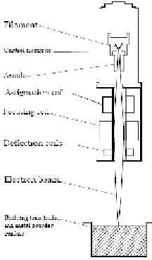
Arcam’s electron beam melting technology is now on the market with its “CAD to
Metal” system to produce fully dense metal parts. It uses a 4.8kW electron beam gun to
melt the metal powder with the electrons’ kinetic energy. The electron beam gun is fixed
on top of the vacuum chamber and it has a cathode, an anode, and an electromagnetic
focusing unit. Emitted electrons from a filament are accelerated towards the build
substrate and controlled with the magnetic fields. The beam focuses on specific regions at
scanning speeds up to 1000m/s as shown in Figure 11. The current commercial models
are the S12 and the A2.
Figure 11: Sketch illustrated the Beam control system Source: EBM manual
2
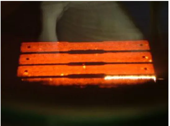
Three-dimensional parts are sliced into 2D layers using special software, similar
to other RP file processing systems. The layers are melted one at the time and then new
powder is delivered at a predetermined thickness. The layer is preheated for initial
sintering and attachment of the powder to the previous layer, and also to help to build
parts with less thermal internal stresses (Cormier, Harrysson et al. 2004). The current
layer is melted after completing the preheating steps and the support structure. After
melting the current layer, a new layer of metal powder is added over the previous one,
and the procedure is repeated. The part is melted slice by slice similar to the other RP
processes as shown in Figure 12. The unmelted powder acts as a support for the part
during the fabrication and is easily removed and reused. Electron beam melting in
vacuum has many advantages over laser sintering systems. It provides high power
efficiency, good material properties, and laser systems are known to have problems with
reflectivity which decreases the power efficiency. The laser lifetime is limited, while the
electron beam is relatively free except for the cost of the filaments. The melting process is
done under vacuum, which eliminates impurities, eliminates oxidation of the molten
material, and yields higher strengths of the materials. The vacuum is costly to maintain
but the vacuum tank is also designed to block any harmful gamma rays. Melting of
reactive materials like titanium can only be done under vacuum and the processing also
prevents oxidation of the unused powder in the machine. The mechanical properties of the
resulting parts are comparable to wrought titanium and better than cast titanium (Arcam,
Sweden). The control system of the electron beam does not include any optics or moving
mirrors as used in the laser based control system. The lasers based systems also need to
electrical-to-optical conversion efficiency of a high-power diode laser unit is around 20 %
with a maximum of 50 % (Lin 2000). However, laser based systems have higher accuracy
and better surface finish compare to the EBM parts.
In the EBM system, parts can be set up with different processing parameters,
which make it possible to build light structures and solid sections at the same time.
Contours and hatches are used to scan the part for preheating, post heating and melting.
The preheating is important for the attachment of the newly spread powder to the
previous layer, which will increase the electrical and thermal conductivity. Invisible
supports are created by further sintering the powder under the down-facing regions. The
scan speed, power settings, hatch properties, and heating parameters can be changed in
the EBM control system. The control of the process parameters in the EBM machine is
similar to the parameter controls in laser based systems (Mazunder, Schifferer et al.
1999). Modeling of the EBM process for melting of solid metals has been reported in the
literature (Vutova and Mladenov 1999). There are also solid-interaction models based on
physics but there is no model for the electron beam interaction with metal powders as
used in free form fabrication systems. One of the important additions to the EBM system
is the wafer supports. This is similar to the break-away supports used in stereolithography
systems and consists of thin porous walls that connect the inclined surfaces to the
platform.
Different metal powders can be used in the machine after the process parameter
development is completed. Powder size, conductivity, and vaporization are important
factors in the selection of the powder. H13 tool steel was the only material available from
Ti6Al4V, Ti6Al4V ELI, and CoCrMo are commercially available for the EBM system
through Arcam (ARCAM, Sweden).
Figure 12 : Electron beam is melting the current layer (CoCr test parts in EBM S12)
Figure 13: EBM build platform with sintered powder surrounding the actual parts.
The EBM has been used to manufacture custom knee implants and custom bone
plates (Harrysson, Cormier et al. 2003; Cormier, Harrysson et al. 2004). The custom bone
plates were designed based on patient specific image data and fabricated using the EBM.
milling machine. Implants with metal mesh coating have recently been manufactured
using the EBM system. New materials have also been processed after developing new
processing parameters. GRCop-84, developed at the NASA Glenn Research Center for
use in regeneratively cooled rocket engines3, has recently been used to build test parts. D.
Cormier et al., 2004, have also produced thin walled Ti6Al4V components and
characterized the material properties as compared to bulky structures (Cormier, West et
al. 2004).
Electron beams are also used for other applications areas and some of them were
developed before the RP methods, such as melting metal at high purity, welding, curing,
lithography, sterilization, high powered beam applications, and film deposition. Baris et
al. studied the coatings of TiN, TiC, TiB2, and δ-MoB powders on a titanium base using
an accelerated electron beam at the nuclear physics lab (Baris, Golkovsky et al. 2000).
The experimental settings were 1.4MeV for the electron beam energy, 20 to 30 mA for
the beam current, and a beam velocity of 103m.s-1. Sterilization is one of the application
areas of electron beam beyond the free form forming techniques. With the increased focus
on the electron beam, the shortest sterilization times can be achieved. Calhoun et al.
reported that the overall processing time including transportation is around 5 to 7 minutes
(Calhoun, Allen et al. 1997).
2.2.
Mechanical Behavior of Metallic Foams
Researchers have been interested in foam materials and their properties for a long
time. Recent work about electrical, mechanical, and thermal properties of the foam
materials helped to understand metal foams and develop new processes for specific
applications (Ashby, Evans et al. 2000; Banhart 2000; Gibson 2000). Many studies have
been done on stochastic metallic foams and some examples are given here. Harte et al.
investigated the fatigue strength of the open cell Al 6101-T6 foam in cyclic four point
bend (Harte, Fleck et al. 2001). Analytical models were developed to predict the fatigue
strength for each of the different failure modes. The fatigue strength and the failure mode
were displayed in a design map as a function of beam geometry.
Nieh studied compressive properties of open cell 6101 aluminum foams with
different densities and morphologies (Nieh, Higashi et al. 2000). It is reported that the
modulus and the yield strengths of the foams were affected by changes in the density.
Aluminum foams were fabricated by using a directional solidification technique. The
compression stress-strain curves showed a general three stage behavior: elastic,
nearly-perfect plastic, and densification as shown in Figure 14. The effect of cell size was
observed to be negligible while keeping the density the same but the cell shape has a
significant influence. Models were developed to show the effect of cell shape and size in
Figure 14: Compressive stress-strain curve for 6101 Al foam (9.2% density), (Nieh, Higashi et al. 2000) reprinted by permission from Elsevier.
Non-stochastic structures or lattice structures are similar to foam materials and
they represent the cellular structures. Mechanical models describe metal foams as bending
dominated or stretch dominated structures (Ashby 2006). The type of the structure is of
importance when deriving the equations. Cellular structures with closed cells or open
cells can show bending dominated behaviors. Maxwell, who is famous in
electromagnetism and other fields, showed that the stability criterion describes when
bending or stretching happens in cells in a simple formulation (Maxwell 1864).
M=b-2j+3 (1)
where b is the number of struts and j is the number of nodes in 2D. The equation
for 3D cases is given below.
M=b-3j+6 (2)
Stretch dominated structures will have M ≥0 and bending dominated structures will have
M<0. A simple schematic shows the difference of mechanism type structures, stiff
Figure 15: a) M<0 and it is a bending mechanism b) M=0 and It is stiff with horizontal beam in tension c) M>0 and it is over-constrained.
Ashby stated that space filling polyhedral cells in 3D do not have structures with M≥0.
However, space-filling combinations of cells have a rigid framework such as the
tetrahedron and the octahedron structures. In metal foams, structures are modeled as
space filling structures and the same unit cell repeats for the entire material volume
(Ashby 2006).
Cell topology and connections define the structure type, and the number of
connecting beams at each node defines the structure mechanism. Their properties are
related to the material they are made of, cell topology, shape, and relative density.
Different scaling laws for mechanical, thermal, and electrical properties have been
derived for bending dominated and stretch dominated structures based on the relative
density. Relative density of the structure was defined in relation to the edge thickness and
cell size. The materials were assumed to be linear and the equations were derived for
plastic yielding, buckling, and fracture (Gibson 2000). Gibson reviewed the elastic
(Gibson 2000). It is stated generally that mechanical properties are independent of the cell
size. Bulk modulus and foam modulus were given as proportional to the square of the
relative density and multiplied by a constant which depends on the structure. In open cell
foams, the modulus is calculated based on the dimensional analysis of edge bending and
given as 2
* 1 * ) ( s s C E E ρ ρ
= . In closed foams, bending and stretching of the faces are
represented as ( ) ( )
* 2 2 * 1 * s s s C C E E ρ ρ ρ ρ +
= , where ρ* is the density of the foam, ρS is the
density of the solid of which it is made. First term represents the bending of the cell edges
and second term accounts for stretching of the faces. Other relations were also given for
yield strength, yield criteria and creep.
Metal foams were also modeled as cellular lattice type structures, because the
skins are very thin and they fail at small loads (Ashby 2006). A generic stress-strain curve
of a cellular solid shows yielding point, plateau stress, and densification is shown in
Figure 16. This behavior is mostly attributable to the plastic failure. Fractures in the
Figure 16: A stress-strain curve of a cellular solid with typical densification.
Crushing will not show densification because it will not have connections to limit the
movement of other node points and prevent further bending or buckling. Examples about
that are given in this section for initial lattice structures. Defects on the lattice or crack
initiation points represent stochastic failure properties. It is also important to say that
other types of failures can happen at the same time besides the main failure type.
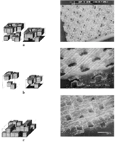
In the literature, lattice structures have been studied for tissue engineering
applications to modify the unit cells for a specific porosity, pore size, and material
properties (Hollister, Maddox et al. 2002; Lin, Kikuchi et al. 2004; Hollister 2005).
Related fabrication methods and topology optimization based design methods for these
applications will be discussed in the following chapter. Structure unit libraries and related
procedures have been discussed in the literature (Fang, Starly et al. 2005; Sun, Starly et
al. 2005; Wettergreen, Bucklen et al. 2005). Image based methods were mostly used in
their studies. Representative unit cells were optimized according to the specific
implant region or the scaffold region. Similar unit cell based replications and Boolean
operations were used in this study to create the implant designs with cellular structures.
There are limitations in layered manufacturing processes in terms of feature sizes,
layer connectivity, material choices, processing parameter flexibility in different features,
and complexity of the build. The layered Electron Beam Melting process has limitations
in terms of structure connectivity, dimensions, and type of features possible without extra
sintering or solid supports. In the next sections, lattice structures with different cellular
designs are discussed and their properties are given from different tests. Some examples
of EBM based cellular manufacturing are also given in an optimization context. The
primary reason for these structures are medical applications, so details about tailoring
structures to specific bone properties are also given below.
Several mesh configurations were tested in the preliminary stages of this research.
Structures with holes were investigated first, but they did not show much difference in
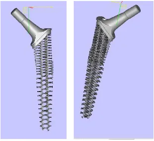
structural elastic modulus compared to solid titanium structures, see Figure 17. Hip stems
based on this design were also manufactured and tested, Figure 18.
Figure 18: Less stiff implant designed with straight holes.
Initial mesh structure designs based on repeating features are given below in
Figure 19, Figure 20, and Figure 21.
Figure 20: Titanium solid model of the honeycomb design made with EBM.
2.3.
Initial hexagon meshes
Arcam developed and provided the basic process parameters for producing lattice
structures in Ti-6Al-4V. The information was used as a starting point to investigate the
process capabilities for lattice structures. The lattice structures were designed using
Solidworks™; commercially available solid modeling software. It was observed that the
cross sectional area assigned to the thin beams of the lattice in the CAD-software varied
from the actual part produced on the EBM system. The first experiment used the original
lattice design with varying cross sectional diameter of the beam elements (0.5 mm, 0.75
mm, and 1.0 mm). The angle at which a beam is built with respect to the XY plane (build
plane), the thickness of the beam, and the layer thickness of the thin structures are of high
importance due to the layered fabrication approach. If the build angle is too low and the
individual beams are thin or the layers are too thick, then there will be a very small
overlap between the adjacent layers. Non-stochastic structures with beams built at an
angle from 10º to 80º to the build plane were designed and fabricated in order to
understand the influence of the beam angle on beam quality.
During the initial experimentations, it was observed that lattices whose struts were
oriented at an angle of less than 20° with respect to the build plane had little or no
structural integrity for small cross sections. Figure 22 illustrates the problem. The default
layer thickness with the EBM process is 0.1 mm. At this layer thickness, it is clear that
continuity between the layers becomes a problem as the strut angle relative to the built
plate decreases for small cross sections. The overlapping distance between adjacent 0.1
thickness , L2 = 0.1mm/tan(α), T is the strut thickness, and α is the angle of the strut with
the build plane.
Figure 22: a) beam thickness is shown before slicing of the beam b) Overlaps, defined as L1-L2, between successive layers are shown with the related parameters.
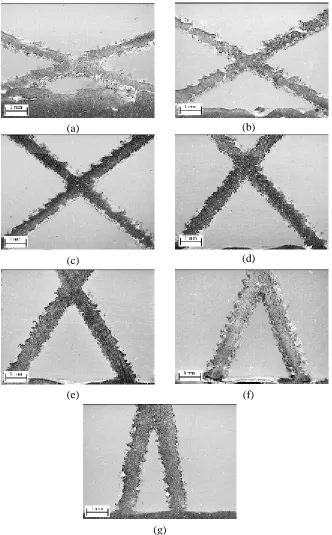
Figure 23 shows a relatively good strut at left and a poor strut at right. Figure 24
show a relatively rough struts at low angles (top row), whereas it shows thicker beams at
high angles with better connectivity (bottom row). These micrographs help to illustrate
that the strut quality is sensitive to the build angle and melting parameters. More
information is given about the effect of the melting parameters and changes in meshes
properties in the next sections.
(a) (b)
Figure 24: Range of Strut Qualities for same beam melting parameters at same micrograph scale a) 20°, b) 30°, c) 40°, d) 50°, e) 60°, f) 70°, g) 80° angle with respect to XY plane
.
(a) (b)
(c) (d)
(e) (f)
From the process capability study it was decided that the struts should be modeled
with a 0.7 mm beam thickness and a minimum angle of 20° with respect to the build
plane in order to achieve good interlayer integrity. Using these parameters, a wide variety
of non-stochastic cell structures were designed in SolidWorks and fabricated on the
electron beam melting machine for mechanical testing. The non-stochastic cell structures
were designed as cubes for crush testing and as beams for flexural testing. However, the
material properties presented in the remainder of this section pertain to the non-stochastic
structures with hexagonal unit cells shown in Figure 25.
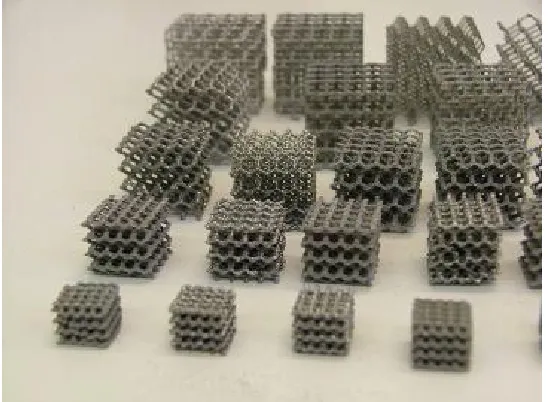
2.3.1. Design and Fabrication of Structures
For compression and flexural testing; cubes and beams with hexagonal unit cells
were designed with different relative densities using 4, 5, and 6 mm unit cells (see Figure
25 ). The cubes were 25 mm x 25 mm x 25 mm and the beams had a length of 192 mm
and 18.5 mm, 23 mm or 27 mm cross section for the different cell sizes. A strut diameter
of 0.7 mm was used with a strut angle of 30 degrees, as described in the previous section.
Lattice structures have repeating beams that have the same angle with the build platform
and equal lengths. The beams have a square profile instead of a round cross section, as it
helps to reduce the STL file size. Due to a close to circular weld pool during melting, the
thin beams have an approximately circular cross section. STL files were exported from
SolidWorks (SolidWorks Corporation, USA) and Magics (Materialise, Belgium) was
used to prepare the build files for fabrication on the Arcam EBM S12 (Arcam, Sweden).
Slicing of the structures was done at 0.1 mm layer thickness. A steel build substrate was
conditions previously described. After the completion of each build the build chamber
was cooled using Helium gas.
(a) (b) (c)
Figure 25: a) Top view shows 0.7mm beam thickness, 4mm cell size, and build angle of 30° b) Front view ,c) Isometric View of Hexagonal Lattice Structure
Figure 26: Compression Specimens with 2mm (not tested),3mm (not tested),4 mm, 5 mm, and 6 mm Unit Cell Dimensions.
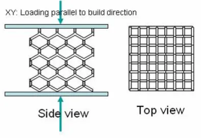
2.3.2. Compression Test Procedure
Material testing was conducted using an ATS 1605C universal tester. The
specimens were compressed between steel plates at the rate of 5 mm/min. Number of
specimens of each size were compressed in the build direction named XY in the testing
protocols. Two specimens of each size were compressed in the perpendicular direction
named Z in the testing protocols as seen in Figure 27. Each specimen was loaded until
failure and the failure mode was recorded using the crosshead displacements. The
compressive strength was calculated based on actual peak load for each specimen. The
elastics modulus was calculated using the load-displacement data from the crosshead
displacements.
Figure 27: Compression test was done using parallels at each face for 4mm, 5mm and 6mm cell sizes
2.3.3. Flexural Test Procedure
Three-point bend testing was conducted using the ATS 1605C universal tester
with a load span of 177.8 mm. The length of the bending specimens was approximately
190 mm. The length to thickness ratio was approximately ten for all bending specimens.
Sample size was more than 7 for each cell size. The flexural modulus was calculated
according to the head-displacement reading from the bend tests. Specimens were tested in
the direction parallel to the build direction.
Head displacements were used to calculate the flexural modulus based on the