Pneumatic Shearing Machine
Pramod S N1 ,Vinay A M2 Amith Sreenivas3 Gireesh.S Manoj.J 4
Assistant Professor, Department of Mechanical Engineering, S.K.I.T Bangalore, Karnataka, India1
8th semester student, Department of Mechanical Engineering, S.K.I.T Bangalore, Karnataka, India 2, 3, 4
ABTSRACT: We are using scissors for simple sheet metal cutting. It is a manual method so that sheet metals are to be wasted sometimes because of mistakes happened such as wrong dimensions etc., and also even a simple cutting may take long time. Hydraulic machines are also available for sheet metal cutting. But this method is used for only heavy metal cutting and its cost is very high. We are using a pneumatic system for sheet metal cutting in a easy way. It is operated by a pneumatic hand lever of two ways control valve. Control valve is operated by a compressor. Sheet metal is simply a metal formed into thin and flat pieces. It is one of the fundamental forms used in metal working and can be cut and bent into a variety of different shapes. Countless everyday objects are constructed of the material. Thicknesses can vary significantly, although extremely thin thicknesses are considered foil or leaf, and pieces thicker than 6 mm(0.25 in) are considered plate. Sheet metal is available in flat pieces or as a coiled strip. The coils are formed by running a continuous sheet of metal through a roll slitter. The thickness of the sheet metal is called its gauge. Commonly used steel sheet metal ranges from 30 gauges to about 8 gauge. The larger the gauge number, the thinner the metal. Gauge is measured in ferrous (iron based) metals while nonferrous metals such as aluminum or copper are designated differently; i.e., Copper is measured in thickness by Ounce. There are many different metals that can be made into sheet metal, such as aluminum, brass, and copper, steel, tin, nickel and titanium. For decorative uses, important sheet metals include silver, gold and platinum (platinum sheet metal is also utilized as a catalyst.)Sheet metal also has applications in car bodies, airplane wings, medical tables, roofs for buildings (Architectural) and many other things. Sheet metal of iron and other materials with high magnetic permeability, also known as laminated steel cores, has applications in transformers and electric machines. Historically, an important use of sheet metal was in plate armor worn by cavalry, and sheet metal continues to 2 have many decorative uses, including in horse tack. Sheet metal workers are also known as "Tin Bashers",("Tin Knockers") which is derived from the hammering of panel seams when installing tin roofs. Hydraulics present certain advantages over pneumatics, but in a given application, pneumatic powered equipment is more suitable, particularly in industries where the factory units are plumbed for compressed air. Moreover, to avoid corrosive actions, oil or lubricants are added so that friction effects can be reduced. Compressed air is used in most of the machines and in some cases compressed carbon dioxide, whereas cutting process is become easy. Fast cutting action is carried out. Cutting without bending is achieved.
I. INTRODUCTION
Pneumatics, from the Greek (pneumatikos, coming from the wind) is the use of pressurized gases to do work in science and technology.
Pneumatics was first documented by Hero of Alexandria in 60 A.D., but the concept had existed before then. Pneumatic products represent a multi-billion dollar industry today. Pneumatic devices are used in many industrial applications. Generally appropriate for applications involving less force than hydraulic applications, and typically less expensive than electric applications, most pneumatic devices are designed to use clean dry air as an energy source. The actuator then converts that compressed air into mechanical motion. The type of motion produced depends on the design of the actuator. Pneumatics is employed in a variety of settings. In dentistry applications, pneumatic drills are lighter, faster and simpler than an electric drill of the same power rating (because the prime mover, the compressor, is separate from the drill and pumped air is capable of rotating the drill bit at extremely high rpm). Pneumatic transfer systems are employed in many industries to move powders and pellets. Pneumatic tubes can carry objects over distances. Pneumatic devices are also used where electric motors cannot be used for safety reasons, such as mining applications where rock drills are powered by air motors to preclude the need for electric motors deep in the mine where explosive gases may be present.
Types of shearing Machine:
Shearing machines are classified according to the following:- 1) Pneumatically operated
2) Hydraulically operated 3) Rack and pinion operated 4) Spring operated
Brief description of all the types are as follows.
1) Pneumatically Operated:-
Here the advancement of the header is carried out in the upward and the downward direction using the pneumatic double acting piston and cylinder unit arrangement along with the foot operated direction control valve. In this type of machine high pressure air is used as the working fluid for the transfer of power and the motion
2) Hydraulically operated:-
Here the lowering and raising of the header is carried over using the hydraulic piston and cylinder arrangement. To actuate the piston and cylinder, the oil is allowed to enter the cylinder from front or the back side of the piston. But the oil is comparatively costlier and its leakage may cause so many problems.
3) Rack and pinion operated:-
Here the lowering and the raising of the header is carried out manually using the rack and pinion arrangement. In this case the required pressure is applied manually using direct hand pressure on the rack using pinion and lever arrangement. Since the machine is robust and requires large pressure, Hence it is not suitable.
4) Spring operated:-
The working of spring operated machine is similar to the rack and pinion operated machine but differs from it in construction. Here the lowering and the raising of the heating handle is carried out manually and it requires too much pressure for its operation and also there is possibility of having damage to the work piece if not handled carefully.
1.1 Construction
Pneumatic cylinder
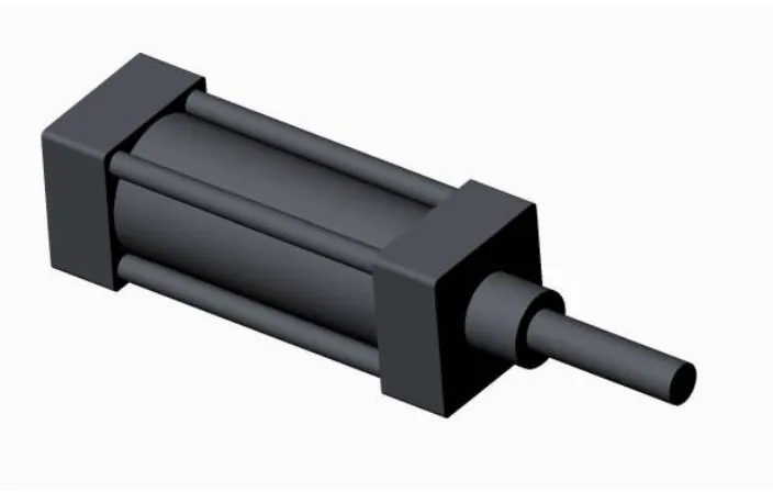
Pneumatic cylinders or air cylinders are mechanical devices used to impart a force from a fluid, typically compressed air.
A typical pneumatic cylinder consists of a piston, piston rod, and a body or tube. Compressed air enters at one end of the tube, imparting force on the piston, which is then displaced (moves) in order to balance the force exerted on the piston. Air cylinders, or actuators as they are also called, are available in a variety of sizes, shapes, and have varying strokes. Typical cylinder sizes range from a small 2.5mm air cylinder, which might be used for picking up a small transistor or other electronic component, to 400mm diameter air cylinders which would impart enough force to lift a car.
1.2 COMPONENTS OF PNEUMATIC SHEARING MACHINE
:-Different components of pneumatically shearing machine are:- 1)Shearing blade
2)Pneumatic cylinder
3)5/2 Direction control foot operated valve 4)Air circulating devices
5) 5) Frame
Double acting cylinder :-
Here we have used double acting cylinder. It is the pneumatic actuator, which is actuated using compressed air. The Force exerted by the compressed air moves the piston in two directions in a double acting cylinder. In principle, the stroke length is unlimited, although buckling and bending must be considered before we select a particular size of piston diameter, rod length and stroke length.
The double acting cylinder consists of
Cylinder tube,
Piston unit,
Double cup packing on piston, rod packing of O rings,
Bronze rod guide,
Piston rod,
End covers (flanges)
Port connection,
Cushion assembly.
The cylinder is manufactured from aluminium solid bar with central bore on lathe machine. It is then made smooth internally using method of honing and lapping. It contains piston and piston rod, which reciprocates to and fro with the application of high pressure air. The piston is fitted with the piston ring which is made of Teflon rubber to make perfect compression of the air. 5/2 Direction control foot operated valve:
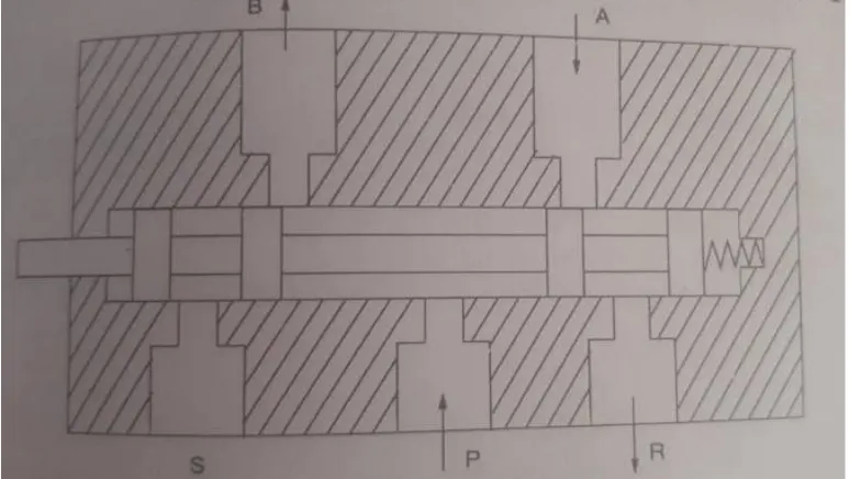
Its basic symbol is as shown
Figure 1.3: 5/2 DC valve -spool type
1.3 Working of 5/2 push button Direction control valve
The working principle is as follows :
Position 1: when the spool is actuated towards outer direction, port P gets connected to ‘B’ and ‘S’ remains closed while A gets connected to ‘R’.
Position 2:when the spool is pushed in the inner direction , port P gets connected to A and R remains closed while ‘B’ get connected to ‘S’.
To control the to and fro motion of a pneumatic cylinder, the air energy has to be regulated, con-trolled, and reversed with a predetermined sequence in a pneumatic system. Similarly one has to control the quantity of pressure and flow rate to generate desired level of force and speed of actuation.
To achieve these functions, valves are used to- (i) start and stop pneumatic energy,
(ii)control the direction of flow of compressed air, (iii)control the flow rate of the compressed air (iv) control the pressure rating of the compressed air.
A direction control valve has two or three working positions generally. They are: 1) Neutral or zero position
2) Working position
The positions are mostly numbered as 0,1,2. Direction control valves are designated to indicate both the number of ways as well as the number of working positions such as 4/2, 3/2,5/2 means 5 ways / 2positions.
Here the spool slides inside the main bore and according that the spool position is made ON or OFF due to the fact that the spool gets connected to the open side or the closed side of the air opening.
Air circulating devices:
The compressed air is stored in an air receiver from which air is drawn out in to the consumer point by means of pipe line.
While laying out the pipe line for the system, one should take sufficient care and pay attention to see that the pressure drop from the generating point to the point of consumption remains as low as possible. For economical reason, it is always better if the total drop of pressure is kept limited to a maximum value of 0.1 bar or even less.
The following factors are taken into account while selecting pneumatic pipeline and other air- line installations:- 1) Pressure of compressed air in the lines.
2) Total flow rate per unit time through the line. 3) Permissible pressure drop in the line.
4) Types of tube material and types of line fitting. 5) Length and diameter of tube or other pipelines. 6) Working environment.
Considering the above factors we have selected the flexible hose tubes of 1/8diameter.
Frame Base :-
It forms the robust support to stand the machine vertically. It holds the weight of the vertical post and supports the direction control valve. It is made of mild steel channels of rectangular base with the vertical post and the horizontal channel at the t.
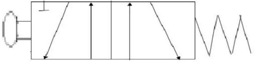
Shearing blade :
Figure 1.4: Return stroke to drag the sheet metal.
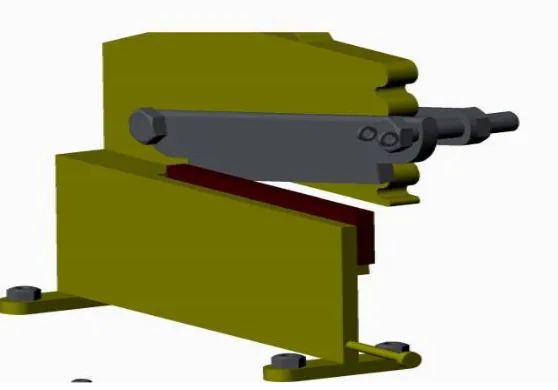
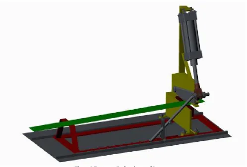
1.4 CONCEPT OF PNEUMATIC SHEARING MACHINE
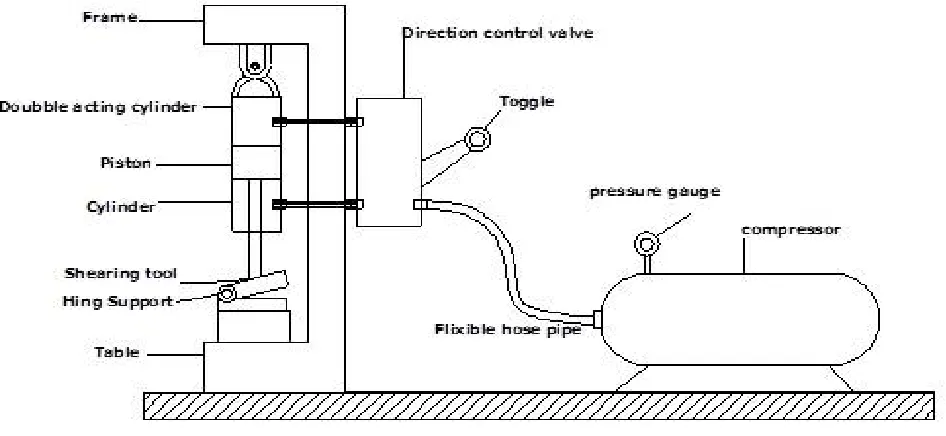
Fig 1.6: Concept of Pneumatic Shearing machine
As shown in above figure a frame is support to all pneumatics & shearing tool of a machine. Here we used a compressor for a generation of compressed air. A compressed air is supply to the double acting cylinder by means of hose pipe& 5/ 2 Direction control valve.
The shearing tool is provided at end of the pneumatic cylinder rod. When compressed air is supply by the DCV to double acting cylinder due to pressure & force created by compressed air causes Shearing action of the sheet metals strips & HSS cutting blades. Here the advancement of the header is carried out in the upward and the downward direction using the pneumatic double acting piston and cylinder unit arrangement along with the hand lever operated direction control valve. In this type of machine high pressure air is used as the working fluid for the transfer of power, force and the motion to the system
II. LITERATURE SURVEY
2.1 ASME Paper No. 57-A-15 (1957)
2.1.1 Summary
The formation of any business begins with someone producing the initial idea for the project. The continued success of an established business depends upon the number and quality of the ideas fed into it. Without a continual flow of new ideas, a business cannot function profitably or expand successfully and must, therefore eventually fade into total obscurity.
Ideas for a new business project, a new product, a means of reducing manufacturing costs, or for solving industrial labour problems, begin in the human mind. Most people conceive their ideas unconsciously, and because they are unaware of the mental mechanics that caused the ’idea’ to be produced, they cannot repeat the ideation process to produce further profitable ideas at will.
Fortunately, there are available established creative techniques which, when used correctly, do enable a person to produce a large number of first-class ideas at will. One such creative technique, and probably the most widely used in American industry, is ’brainstorming’.
place in a localized area and the metal adjacent to the cutting edges of the punch and die edges becomes highly stressed, which causes the fracture to start on both sides of the sheet as the deformation progresses and the sheet is sheared.
2.1.2Advantages
Like hydraulics, pneumatics is a type of fluid power application where instead of an incompressible liquid, pneumatics employ gas in their system.
Hydraulics present certain advantages over pneumatics, but in a given application, pneumatic powered equipment is more suitable, particularly in industries where the factory units are plumbed for compressed air.
The air used in pneumatic devices is dried and free from moisture so that it does not create any problem to the internal parts of the system.
Moreover, to avoid corrosive actions, oil or lubricants are added so that friction effects can be reduced. Compressed air is used in most of the machines and in some cases compressed carbon dioxide.
As most of the pneumatic devices are air based, they have a less complicated design and can be made of inexpensive material
Mass production techniques can be adopted to produce pneumatic systems, which not only save money but save time too
Initial cost is less; hydraulics equipment cost as much as twice the price of pneumatic equipment.
For opening and closing valves, pneumatic systems work well because they can sustain overload pressure conditions.
Pneumatic actuators also have long life and perform well with negligible maintenance requirement throughout their life cycle.
Very suitable for power transmission when distance of transmission is more.
In a nutshell, in order to execute low scale engineering and mechanical tasks, pneumatic devices would be the best suited and a viable alternative over hydraulic systems.
Also, hydraulic systems are dirtier than pneumatic system
III. CONSTRUCTION AND WORKING
OBJECTIVE
1)To reduce the power consumption during machining.
2)To maintain the accuracy & reduced the scrap of HSS blades.
3)To develop automation unit for the Shearing, so that m/c can easily be adopted in today’s automated plants. 4)This type of m/c provides work practically at low cost, low maintenance, low capital investment in less space. 5)To perform the most rigid operation with high speed.
To prepare any machine part, the type of material should be properly selected, considering design, safety and following points:- The selection of material for engineering application is given by the following factors:-
1) Availability of materials.
2) Suitability of the material for the required components. 3) Suitability of the material for the desired working conditions. 4) Cost of the materials.
In addition to the above factors the other properties to be considered while selecting the material are as follows:- 1) Availability of materials.
2) Suitability of the material for the required components. 3) Suitability of the material for the desired working conditions. 4) Cost of the materials.
In addition to the above factors the other properties to be considered while selecting the material are as follows:- Physical properties:-
Mechanical
properties:-The properties that are associated with the ability of the material to resist the mechanical forces and load. properties:-The various properties are:-
1) Strength : It is the property of material due to which it can resist the external forces without breaking or yielding. 2) Stiffness : It is the ability of material to withstand the deformation under stress.
3)Ductility:It is the property of material due to which it can be drawn into wires under a tensileload. 4) Malleability: It is the property of material which enables it to be rolled into sheets.
5) Brittleness: It is the property of material due to which it breaks into pieces with little deformation. 6) Hardness : It is the property of material to resist wear, deformation and the ability to cut another material. 7) Resilience: It is the ability of the material to store energy and resist the shock and impact loads.
8) Creep: It is the slow and permanent deformation induced in a part subjected to a constant stress at high temperature. We have selected the material considering the above factors and also as per the availability of the material. The materials which cover most of the above properties are:-
MILD STEEL :
Why steel in particular?
Simply because, in my humble opinion, it is the greatest material mankind has for construction. It is cheap, strong, readily available, easily cut, joined, and formed. Wood can be light and stiff, but not very strong. The best aluminium is strong and light, but very difficult to join. Titanium is superb in terms of strength to weight ratio and stiffness but its incredibly expensive, difficult to obtain, and even more difficult and expensive to machine properly. There no way you're ever going to perform a battery-weld field-fix on a part made from 7075-T6 aluminium or titanium! In the end we come back to steel from mild carbon to some of the more exotic alloy steels pound for pound it is the most righteous material available for our needs.
Where does steel come from? Steel is not a naturally occurring substance - it is entirely man made. Steel is chiefly a combination of two naturally occurring elements: iron and carbon (along with small amounts of other elements - depending on the steel in question). The process by which man makes steel, would, again, fill several volumes.
Iron is mined from the ground in the form if a reddish-brown rock called iron-ore. This ore is then smashed up, strained, filtered, chemically treated etc, until ultimately it is melted in huge blast furnaces into something called pig iron. The process uses coke (a type of coal), which in turn imparts large amounts of carbon to the pig iron. As a result, pig iron itself is full of impurities, brittle, and un -machinable - practically useless. Except - it is the raw material from which all other irons and steels are made. Pig iron is so produced in either huge vats of molten material, or it is cast into ingots (in fact, pig iron got it’s name because the ingots or ”chunks” produced were thought to have resembled piglets). Pig iron is then refined into either metallic iron or steel using specialized furnaces and processes. The distinction between the two is that metallic iron has between 2-6
A final word about carbon. carbon is critically important to our whole discussion because it is the presence of carbon that turns the element of iron that is naturally soft and weak, into the strong, rigid materials we know as iron and steel. Precisely how this is so is beyond the scope of this article, suffice to say: The strength, hardness and toughness that make the ferrous based metals useful to us are profoundly influenced by the remarkable sensitivity of the physical and chemical properties of iron crystals to relatively small percentages of carbon dissolved within their matrix (actually, the sensitivity is to the movement of dislocations within the crystal space lattice). This sensitivity to dissolved carbon is in fact, the very basis of ferrous metallurgy.
3.1 MACHINE CONSTRUCTION
The machine is basically made up of mild steel. Reasons:
1) Mild steel is readily available in market 2) It is economical to use
3) It is available in standard sizes
4) It has good mechanical properties i.e. it is easily machinable
5) It has moderate factor of safety, because factor of safety results in unnecessary wastage of material and heavy selection. Low factor of safety results in unnecessary risk of failure
7) Low co-efficient of thermal expansion
Properties of Mild Steel:
It is a machine drawned. The main basic difference between mild steel and bright metal is that mild steel plates and bars are forged in the forging machine by means is not forged. But the materials are drawn from the dies in the plastic state. Therefore the material has good surface finish than mild steel and has no carbon deposits on its surface for extrusion and formation of engineering materials thus giving them a good surface finish and though retaining their metallic properties
A poor, but perhaps useful metaphor may be the use of fibre-mat and resin in fibre glass work. The bulk raw material of fibreglass is the fibre matting (as iron is to steel) - but by itself the matting is of no practical use. Not until we add the resin to it to make fibre glass (as we add carbon to iron to make steel) do we get a useful product. In both cases, neither raw material is much use alone, but combines them nor do we really have something. Similarly, though carbon may only be present in small quantities, just as the amount of hardener added to fibre glass resin has a profound effect on the material, so does the small amount of carbon present in useful metallic iron and steel.
The pneumatic shearing machine consists of following components 1.Pneumatic double acting cylinder
2. 5/2 Push button DC valve 3. Shearing blade with frame 4. Sheet drawing mechanism 5.Column for pivoting cylinder
Figure 3.1 Pneumatic double acting cylinder
cylinder will not drip out and contaminate the surroundings, making pneumatics more desirable where cleanliness is a requirement
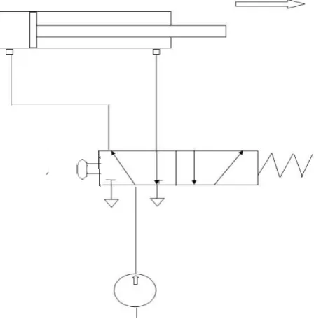
Figure 3.2 .5/2 direction control valve
Pneumatic systems like hydraulic system also require control valves to direct and regulate the flow of fluid from the compressor to the various devices like air actuators and air motors. In order to control the movement of air actuators, compressed air has to be regulated, controlled and reversed with a predetermined sequence. Pressure and flow rates of the compressed air to be controlled to obtain the desired level of force and speed of air actuators. The function of directional control valve is to control the direction of flow in the pneumatic circuit. DCVs are used to start, stop and regulate the direction of air flow and to help in the distribution of air in the required line.
A shear force is applied that will cut off part of a sheet. The cut off ‘blank’ becomes the work piece. Shearing, also known as die cutting, is a process which cuts stock without the formation of chips or the use of burning or melting. In strict technical terms, the process of “shearing” involves the use of straight cutting bladesorm of sheet metal or plates, however rods can also be sheared. Shearing-type operations include: blanking, piercing, roll slitting, and trimming. When you apply a high pressure tool through a metal plate and remove part of the metal, the process is called shearing. Shear machining devices include punching machines, which make small discs, and blanking machines, which produce washers and similar objects.
Direct tool ordinary machining is NOT the same as shear machining. With standard tool machining, a single or multiple point tool can be employed to take out a piece of metal from the metal sheet and/or block. This process required repeated pounding of the metal until the required dimensions are achieved. With shear machining, the tool’s cutting edge removes the metal from the plate. While this happens, maximum pressure is applied. The tool, however, only touches the metal one time.
Both mechanical and hydraulic machines can perform shear machining. Hydraulic shears cut and score sheet metal quickly and accurately. They work well for factories that do a lot of metal fabrication. In addition, hydraulic shears are best if the operation requires intense pressure. They don’t require a lot of maintenance, will operate continuously, and are fast and quiet. Hydraulic shear machines also take up less space than mechanical shear machines while applying the same amount of pressure.
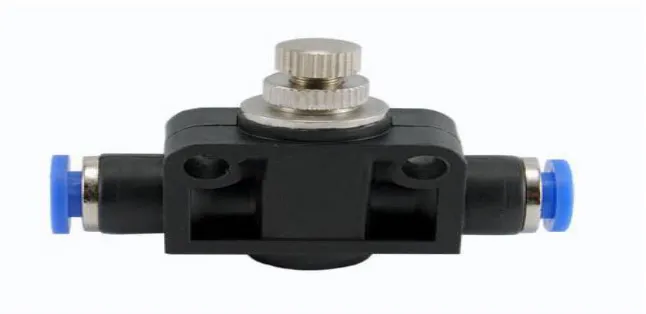
Figure 3.4. Air flow control valve
In-line flow control valves feature finely threaded stems that allow for gradual adjustment of the controlled flow passing through the valve. The pneumatic system’s air flow enters via the input port, travels through an orifice sized by the tapered stem, and out via the output port. Our pneumatic flow control valves include a bypass check which allows rapid free flow from the output through the input port. Finely threaded stems allow gradual adjustment of controlled flow to match system requirements.
We offer two types of air flow control valves. Their selection and placement within a pneumatic circuit will greatly affect the function of an actuator.
A meter-in flow control valve (also known as a reverse flow control valve) restricts the flow to an actuator.
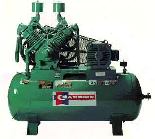
Figure 3.5 Pneumatic air compressor
An Air Compressor Is A Device That Converts Power (Using An Electric Motor, Diesel Or Gasoline Engine, etc.) into potential energy stored in pressurized air (i.e., compressed air). By one of several methods, an air compressor forces more and more air into a storage tank, increasing the pressure. When tank pressure reaches its upper limit the air compressor shuts off. The compressed air, then, is held in the tank until called into use. The energy contained in the compressed air can be used for a variety of applications, utilizing the kinetic energy of the air as it is released and the tank depressurizes. When tank pressure reaches its lower limit, the air compressor turns on again and re-pressurizes the tank.
A pipe is a tubular section or hollow cylinder, usually but not necessarily of circular cross-section, used mainly to convey substances which can flow liquids and gases (fluids), slurries, powders, masses of small solids. It can also be used for structural applications; hollow pipe is far stiffer per unit weight than solid members. In common usage the words pipe and tube are usually interchangeable, but in industry and engineering, the terms are uniquely defined. Depending on the applicable standard to which it is manufactured, pipe is generally specified by a nominal diameter with a constant outside diameter (OD) and a schedule that defines the thickness. Tube is most often specified by the OD and wall thickness, but may be specified by any two of OD, inside diameter (ID), and wall thickness.
BLOCK DIAGRAM
Air compressor
DCV
Double acting cylinder
Shearing machine
3.2 Working Of Pneumatic Shearing Machine
Figure 3.7 pneumatic shearing machine
Before starting the machine following procedure to be followed.
1.Initially the sheet metal supporter should be placed in extream end position (initial posistion of the sheet supporter ) 2.Place the sheet over the supporter in such a way that,one end extened 5cm(50mm)
From the blade (this is length of sheet to be cut)
3.working pressure of air to be supplied to the cylinder through 5/2 push button DC valve Port 1: connected to the air compressor
Port 2: connected to the cylinder port
Port 3:exit port (after stroke it allow the air to atmosphere) Port 4: connected to the cylinder port of the other side Port 5: exit port (after stroke it release the air to atmosphere)
Forward stroke to cut the sheet :
Backward stroke to Drag the sheet:
When releasing the actuating 5/2 push button valve,due to the spring force port 1 the working pressure of air enter in to the other side of the cylinder through port 4,then piston moves backward stroke which helps to drag the sheet to cut and port 5 remains closed ,while port 2 gets connected to port 3 to release the air from the cylinder through port 2 and exit air to atmosphere through port 3.
IV. DESIGN METHODOLOGY
4.1 Requirement Analysis
GENERAL CONSIDERATION IN MACHINE DEVELOPMENT First Stage Design Consideration In New Machine
The word design means different things to different people a wallpaper pattern a fashionable dress, the appearance of a racing car and so on. We therefore start by defining what we mean by design in the present context ie. What design is all about. This understanding will lead to an examination of
Why we need to design particularly in an engineering environment
How we might best go about designing
What is design ?
The Concise Oxford Dictionary explains design as a mental plan a scheme of attack, end in view, adaptation of means to ends preliminary sketch for picture invention Evidently there is a lot more to design than mere visual aspects, and design is not restricted to engineering. Key components of this explanation are as follows
Means to ends implies that we design not for the abstract mental exercise, but with a definite goal in view some action or some physical object will result from the design.
Mental suggests that design is a thinking process. When we design we deal primarily with ideas, with abstractions rather than with numbers - and computers for example cannot do the job for us, though they can help in certain tasks.
No matter what we design, it is vital that we develop and apply our imagination to visualise realistically the future form of the artefact or action, how it will eventually come into being and most importantly how it will thereafter interact with people and other artefacts or actions.
Plan, scheme infers that design is distinct from implementation. Designers especially in engineer-ing seldom execute their plans, but rather communicate them to others either by word of mouth, or visually.
So, can we now define design completely? No ! and neither do we need to. A rigid definition im-plies a rigid process, and design is anything but that. We shall adopt the following interpretation as it incorporates the above concepts and conveys a reasonably clear idea of what design is all about Design is the application of creativity to planning the optimum solution of a given problem and the communication of that plan to others. Apart from the communication aspect therefore, we understand the essence of design to be problem solving, though the type of problem encountered in design is not like a typical text-book mathematics problem for example in which the unique correct solution is guaranteed by following, automaton-like, a series of learned solution steps. A design problem on the other hand is a real-life problem with many solutions, some of which meet the problem requirements better, some worse, and where the process of discovering the solutions is not mechanistic. Some problems might appear not to need design as a solution can be cobbled together without much thought. This is true enough if the solution can be based on direct experience. However we shall soon come to realise that without experience such a thoughtless solution usually comes to grief sooner or later the more involved the problem and the more folk affected by the solution the more likely is the solution going to fall in a heap. Any old solution will not do we must strive for the optimum solution.
We expect that the design process, if properly carried out, will show a high probability of disclosing a solution which is optimum or close-to-optimum, if indeed a unique optimum exists.
Why do we design ?
Most people these days exist by providing thingsto others in the case of engineers these things are technical muscle-power or knowhow, or physical artefacts that is solutions to buyers or hirers particular problems. If these clients are not completely satisfied with the thing provided then they will dismiss the provider, go somewhere else for their next thing and tell everyone about the provider’s unsatisfactory things. If this happens often enough to a particular provider then that provider will cease to exist as a market force nobody will want to know.
So clearly, if things are not designed with care and attention to clients needs then the provider will have problems.
4.2 DESIGN PARAMETERS:- STATEMENT FOR DESIGN:
1) Calculation of cutting force on blade.
Let, A = Area of cross-section of blade which is to be cut by shearing machine A = (width x thickness) A = (30 x 0.71) mm2
Let, we have the Maximum shear stress for the mild steel= 0.5 times the yield stress =0.5* 245MPa
ፘ max =122.5 N/mm2
Calculation for cutting force from the blade
Force from the blade = t×L1× ፘ max L1= length of blade involve in shearing is 30 mm
W=width of the blade involved in shearing is 0.71mm Force from the blade = 0.71×30 ×122.5 = 2609.25N
2) Calculation for force required to cut the sheet
Case 1: If the size, thickness of sheet t=2mm and length of sheet involved in shearing L2=10mm then
F=t×L2×122.5
F=2×10×122.5 F=2450N
This is the force required to cut the sheet metal
Case 2: If the size, t=1mm and L2=5mm then
F=t×L2×122.5
F=1×5×122.5 F=612N
This is the force required to cut the sheet metal
3) Design of a cylinder for cutting operation
Since the Max. force from the blade =2609.25 N And pressure supplied by compressor =10bar Therefore,
Force applied by the cylinder, F = ( /4) × d2×p Where P=10 bar =1 N/mm2
2609.25= ( /4) × d2×1→d=58.27 mm
For safety , we have taken the cylinder of diameter 60 mm.
V. APPLICATION AND RELATED WORK
self-contained solid propellant pneumatic servo may be half that of an equivalent self-self-contained hydraulic system. Where a pneumatic system is to replace a heavier hydraulic system, maximum dynamic response and output stiffness are essential. The outstanding difference between pneumatic and hydraulic systems arises from the low bulk modulus of the pneumatic working medium. The bulk modulus of a gas is p, where hh is the ratio of specific heats for the gas and p is the instantaneous pressure. This is the major obstacle in achieving a high response pneumatic system. Several countries have been investigating and developing active suspension technologies in order to improve both vertical and lateral ride quality of fast train passenger cars. (Cho et al., (1985). investigated the use of actively controlled pneumatic actuators in parallel with conventional passive suspension to improve vehicle dynamics. The use of pneumatic actuators for vehicle active suspension reduced the rms car body lateral suspension stroke by 34 percent with a power requirement of 5.7 KW per car. (Singh et al., 1985). Described the design process by which the air brake control valves of heavy and medium duty trucks were centralized modulus. Truck air brake control systems were reviewed and a floor mounted pneumatic application valve acting on a centrally advanced design was developed using dash mounted electrical controls and a floor mounted pneumatic application valve acting on a centrally located electro pneumatic controller. The system performance was demonstrated on an operational truck and tested to the applicable system requirements of federal brake regulations. Nearly all-modern process plants employ control valves, which use either pneumatic or electric actuators, the choice between the two being normally dictated by the size of the valve, the environment, media and availability of power source. (Clements et al., 1985). Have developed dedicated electro pneumatic positioned for a class of process valves. The position uses solid-state electronics to combine the functions of both the electric to pneumatic converter and valve position-er. Such are the savings in size and weight that have been achieved by the use of electronics that the resulting unit is housed in an enclosure small enough to be mounted directly on the actuator, which it is to operate. (Virvalo et al., 1988). Showed that
electropneumatic servo systems are viable alternatives to hydraulic systems for control of such machines as robots, but most of the research has been carried out on them using comparatively small cylinders. They have studied the problems involved in using heavier versions and have produced a satisfactory method of coping with the somewhat complex problems involved in designing such systems, since with a few simplifications a nonlinear model of a pneumatic servo system can be built and used to time the regulator. An interesting pneumatic servomechanism, which employs pulse width modulation driving technique, was reported by (Sano et al., 1988). A new electro pneumatic on- off valve with a disk flapper driven by a pulse motor was developed.
Experimental tests showed the positioning accuracy and the output power are tolerable but the speed of the response is comparatively less than those of other pneumatic servomechanisms. The advantages and limitations of the conventional pneumatic cylinder were discussed by (Bird et al., 1985). Recent developments in the design of pneumatic linear actuators have resulted in the production of more compact and betterguided actuators. The author worked on the development of special servo control system and its integration into complete control system. Typical applications of such systems are also given. (Vincent et al., 1989) investigated an alternative approach to the design of controllers for positioning damping.
To avoid conflicting requirements problem associated with traditional state variable feedback design, the design is based on energy methods and is not a full state variable feedback design. The method is illustrated using a low order spring mass example, and the results are compared with a linear quadratic design. Electro hydraulic and electro pneumatic servo drives can provide precise position control for a multitude of industries from textile manufacture to machine tools. A significant application of the latter type was in a universal rotary machining centre
control of a joint. A physical actuator model was designed and used as the basis for a subsidiary torque control. Experiments showed that the
static hysteresis nonlinearity of the actuator is less important than the dynamic one. The research focused on the modification of a physical static model and the extension with a dynamic part. The quality of the model was verified by implementing it as a torque controller and running experiments on a test bed (Joachim et al., 2003).Also the pneumatic actuators are extensively used in conveying systems to transport granular materials. A methodology combining theoretical and experimental techniques for characterizing and predicting the friability of granules in a laboratory scale pneumatic conveying systems was developed by (Pavol et al., 2008).
VI. SAFETY MEASURES WHEN USING PNEUMATIC SYSTEMS
Compressed air can cause serious damage to the human body if they enter the body through ducts like the oral cavity or ears.
Under high temperature, compressed air can pass through human skin.
Compressed air released from the exhaust contains particles and oil droplets, which can cause damage to eyes.
Even though the pressure of compressed air in pipes and reservoirs is relatively low explosions may still occur.
Before switching on a compressed air supply unit, one should thoroughly inspect the whole circuit to see if there are any loose parts, abnormal pressure or damaged pipes.
Improve fitting due to the high pressure built up inside it. Therefore, each time before the system pressure is increased; thorough inspection of the entire circuit is required to prevent accidents.
As the force produced by pneumatic cylinders is relatively large, and the action is usually very fast, you may suffer serious injuries if you get hit by a cylinder.
Switches should be installed on the compressed air supply unit to allow easy and speedy control of air flow.
In case of a leakage, the compressed air supply unit should be turned off immediately.
The compressed air supply unit must be turned off before changes can be made to the system.
Stay clear of the moving parts of the system. Never try to move the driving parts in the mechanical operation valve with your hand
ADAVANTAGES AND DISADVANTAGES
6.1 ADVANTAGES
Machine work on the low power consumption as compare to the old Shearing machine.
It provides multiple cutting sizes of the metallic blades &alluminium sheets.
The operation of the new Shearing machine is well controlled.
Complex shapes can be Shearing as per requirement easily.
Very thin sections up to 0.5mm to 1mm can cut easily.
Well balanced system.
It approximately matches the efficiency of old Shearing machine in low cost
Only simple support structures are required Design & fabrication is easy.
It is a faster process of Shearing.
Wide variety of cork, aluminum sheet & plastic sheets can be cut.
Highly accurate profiles and good cutting finishing can be easily obtained.
Metal removal cost & Initial investment is low.
Operation is noiseless.
More accurate and economical in mass production.
A finished work pieces are made at each stroke of the operation.
It reduced undesirable deflection in punching force/pressure.
6.2 DISADVANTAGES
Dimensional accuracy of cutting Blades & sheets is depends on the performance of the operator.
Production rate for Shearing is depending on feed rate of the operator.
Constant monitoring is required to avoid the material scrap.
Balancing problem of cutting die may affect the cutting speed & feed of machine.
Depth of cut depends on blade height approximately 1mm maximum.
Additional operation of scrap removal is needed.
Sheet more than 2 mm thickness cannot cut easily.
Compressed air is must.
Foundation is required also safety major must be taken
VII. FUTURE SCOPE
If we adjust the arrangement of piston at centre of frame & by adding a punching dies to piston end & adding additional a base table we can use this machine as “Pneumatic Punching machine” also for punching work.
By using automation & electronics system we can improve the performance of Pneumatic shearing machine particularly designed for Cutting Dies blades, cork, leather, plastic and PVC materials etc. Most Handsome and compact patronized Model requires Minimum Space. Minimum "Make-Ready" Time and provides sufficient hourly production.
By using proper balancing of pneumatic systems & reciprocating parts we can use this Pneumatic shearing machine for high speed & high production rate applications.
By using proper pneumatic balancing weight of parts we can use this pneumatic shearing machine for cut the hard material & for more thick sheets or blades.
Improve performance by adopting imported guide rails stopper, advanced controlling system and our special designed software.
Automatic tracing system, by using counter will be use for counting the cutting strokes.
Match up our multi-function Pneumatic shearing machine, can realize the full automatic processing of cutting/ punching.
If we increase pressure of working air then we cut different thickness of blades by different forces.
VIII. CONCLUSION
The range of the cutting thickness can be increased by arranging a high pressure compressor and by installing more hardened blades.
This machine utilizes the return stoke to drag the sheet metal for successive cuttings.
This machine can also be made automatic by using sensors and actuators.
Pneumatic shearing machine is less complex and cheap as compared to Hydraulic machine.
It is a special purpose machine which is portable.
REFERENCES
1. J. P. Den Hartog, Advanced Strength of Materials (McGraw-Hill, New York, 1952), TA 405 D4, 1952. ; Author Name, Conference Name, year etc
2. E. W. Comings, High Pressure Technology (McGraw-Hill, New York, 1956). ; Author Name, Con-ference Name, year etc
3. ”Adaptive Steady State Genetic Algorithm for scheduling university exams”,AlSharafat W.S.; Al-Sharafat M.S., Networking and Information Technology (ICNIT), 2010 International Conference on , vol., no., pp.70-74, 11-12 June 2010 doi: 10.1109/ICNIT.2010.5508555
4. http://google.com 5. http://www.engineersedge.com/ 6. http://www.efunda.com/ 7. http://www.steeltubeinstitute.org/ 8. http://www.emjmetals.com/ 9. http://www.usstubular.com/ 10. Machine design R.S. Khurmi 11. Work shop technology R.K.Jain. 12. Machine tool design handbook. 13. P.S.G. Design Data Book