IJEDR1602182
International Journal of Engineering Development and Research (www.ijedr.org)1041
________________________________________________________________________________________________________ Abstract – Reversible logic is very promising due to its low power consumption. There are no. of works have been reported on reversible combinational circuit design. However less work on sequential circuit. This paper proposes the following:1) Construction of Basic Reversible Logic Gate and using these gate construct reversible sequential circuit. 2) Construction and Comparisons of R1 based decoder circuit with proposed decoder circuit in term of delay. The proposed structure has been designed and simulated on XILINX 12.2 tool in Verilog language.Index Terms - reversible logic and gates, flip flop, garbage, sequential circuit.
________________________________________________________________________________________________________
I.INTRODUCTION
An operation p is said to be adiabatic or physically reversible if there is neither energy to heat conversion nor change in entropy due to p. In reversible logic, the state of the computational device just prior to an operation is uniquely determined by its state just after the operation. In other words, no information about the computational state is lost. Thus, the systems realized using reversible logic can be viewed as deterministic state machines. LANDAUER [1] states that irreversible logic operations dissipates kTln2 J of heat energy for every bit of information loss, where k is Boltzmann’s constant and T is the absolute temperature at which the operation is done. Zhirnov et al. [2] predict that this heat dissipation would become impossible to remove by 2020 if Moore’s Law continues to be in effect by doubling the circuit density in every 18 months. Bennett [3] shows that from thermodynamic point of view, kTln2 heat dissipation would not occur if a computation is done in reversible manner. This theoretical thermodynamic limit can be achieved only if the circuit is both logically and physically reversible. Thus, reversible logic may be a favorable logic by dissipating less heat than the thermodynamic limit of kTln2 for the emerging computing technologies. Thus designing practically reversible circuit has become very important. Paper consists of different section. Section II represent the construction of reversible gate, reversible sequential circuit. Section III compares two decoder circuits R1 based decoder circuit and proposed decoder circuit. Section IV represents reversible multiplexer and section V represent simulation result for above reversible circuits. Section VI concludes the paper.
.
II.REVERSIBLEGATEANDREVERSIBLESEQUENTIALCIRCUIT
Reversible gate and reversible circuits are those circuits in which no. of inputs and no. of outputs are same means if there are 2 inputs then there is 2 outputs. If no. of inputs are n then no. of outputs are n. so (n×n) circuit is there. There is one to one mapping between input and output vectors. A detail description of reversible gate describe in literature [4].some are Feynman gate [5] [Fig 1(a)],Toffoli gate[6] Fig 1(b), Fredkin gate[7][Fig 1(c)],Universal reversible gate [1(d)].
(a)
IJEDR1602182
International Journal of Engineering Development and Research (www.ijedr.org)1042
(d)
Fig1. Reversible gate (a) Feynman. (b) Toffoli . (c) Fredkin. (d) Universal reversible gate.
Universal reversible gate is as follow:-
1) by setting input c to 0(1), the OR and AND (NOR and NAND) of inputs a and b are realized in o3 and o1, respectively; 2) by setting b to 1, the XOR of a and c is realized;
3) by setting a and b to ’0’ a two-fan-out circuit of c is realized in o1 and o3, respectively. REVERSIBLE SEQUENTIAL ELEMENTS
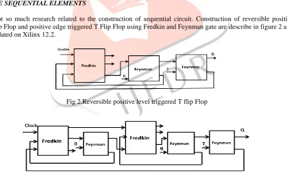
As there is not so much research related to the construction of sequential circuit. Construction of reversible positive level triggered T flip Flop and positive edge triggered T Flip Flop using Fredkin and Feynman gate are describe in figure 2 and 3 and these are simulated on Xilinx 12.2.
Fig 2.Reversible positive level triggered T flip Flop
Fig 3.Reversible positive edge triggered T flip Flop
III. COMPARISION OF R1 BASED DECODER CIRCUIT TO PROPOSED DECODER CIRCUIT
REVERSIBLE DECODER CONSTRUCTION USING R1 GATE
IJEDR1602182
International Journal of Engineering Development and Research (www.ijedr.org)1043
Fig 4. R1 gate, truth table for decoder circuit
Fig 5. Reversible decoder using R1 gate PROPOSED DECODER CIRCUIT
Proposed decoder circuit describes in [9] Figure 6 which uses three fredkin gate (F1,F2,F3).A and B are the inputs of decoder , E is the enable and O1,O2,O3,O4 are the outputs bits of the decoder circuit. By the use of proposed technique delay of the decoder circuit can be reduced and garbage outputs (the final output that is not used as the primary output) can also be reduced.
Fig 6. Two-to-four reversible decoder using Fredkin gate
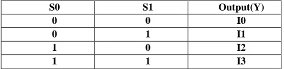
IV. REVERSIBLE MULTIPLEXER
A multiplexer has n select lines , 2n input data and one output. These select line select the input to send the data to output. A multiplexer is also called a data selector. Reversible multiplexer is a combinational circuit which selects one input from all inputs depending upon select line. Truth table describes the 4:1 mux.Here F1, F2, F3 three fredkin gates used each acts as a 2:1 mux.F3 gives the output. Depending of the value of select line output can be any of the input.
S0 S1 Output(Y)
0 0 I0
0 1 I1
1 0 I2
IJEDR1602182
International Journal of Engineering Development and Research (www.ijedr.org)1044
Fig 7. Reversible 4:1 multiplexerV. SIMULATION RESULTS
Simulation result of Feynman gate
Simulation result of Fredkin gate
IJEDR1602182
International Journal of Engineering Development and Research (www.ijedr.org)1045
Simulation result of positive edge triggered T flipflop
Simulatin result of R1 based decoder circuit
Simulation result for reversible decoder circuit
TABLE
Simulation result for two to four decoder circuit
Type Delay
R1-based decoder 6.039ns
IJEDR1602182
International Journal of Engineering Development and Research (www.ijedr.org)1046
Simulation result for reversible 4:1 Multiplexer circuit VI.CONCLUSION
This paper proposed reversible sequential and combinational circuit of digital circuit by using reversible gate. This paper compares two decoder circuit i.e. R1 based (using R1 gate) and fredkin gate based decoder which results that fredkin gate based decoder has less delay and less garbage output than R1 based decoder circuit. By the use of this approach reversible 4:1 multiplexer is designed and these circuits are designed using Xilinx 12.2 tool and simulated on Isim simulator.
REFERENCES
[1] R. Landauer, “Irreversibility and heat generation in the computation process,” IBM J. Res. Develop., vol. 44, pp. 183–191, Jan. 2000.
[2] V. V. Zhirnov, R. K. Cavin, J. A. Hutchby, and G. I. Bourianoff, “Limits to binary logic switch scaling—A Gedanken model,” Proc. IEEE, vol. 91, no, 11, pp. 1934–1939, Nov. 2003.
[3] C. Bennett, “Logical reversibility of computations,” IBM J. Res. Develop., vol. 17, no. 6, pp.525–532, 1973.
[4]R. Landauer, “Irreversibility and heat generation in the computing process,” IBM J. Res. Develop., vol. 5, no. 3, pp. 183– 191, Jul. 1961.
[5] P. Kerntopf, “Synthesis of multipurpose reversible logic gates,” in Proc. Euromicro Symp. DSD, 2002, pp. 259–267. [6] R. Feynman, “Quantum mechanical computers,” Opt. News, vol. 11, pp. 11–20, Feb. 1985.
[7 ]T. Toffoli, “Reversible computing,” in Proc. Automata, Lang. Program. Conf., 1980, pp. 632–644.
[8] E. Fredkin and T. Toffoli, “Conservative logic,” Int. J. Theor. Phys., vol. 21, no. 3/4, pp. 219–253, Apr. 1982.
[9] D. P. Vasudevan, P. K. Lala, J. Di, and J. P. Parkerson, “Reversible logic design with online testability,” IEEE Trans. Instrum. Meas., vol. 55, no. 2, pp. 406–414, Apr. 2006
[10] Sk. Noor Mahammad and Kamakoti Veezhinathan,“ Constructing Online Testable Circuits Using Reversible Logic”, IEEE transactions on instrumentation and measurement, vol. 59, no.1, pp.101-109,january 2010.
[11] Himanshu Thapliyal, M.B Srinivas, Novel Reversible 'TSG' Gate and Its Application for Designing Components of Primitive Reversible/Quantum ALU, IEEE, 2005.